Labkotec SETOS2 Liquid Level Detection Sensor
General Information
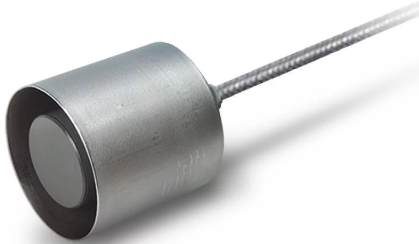
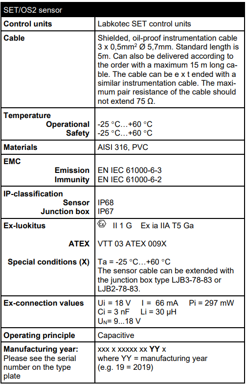
SET/OS2 is a level detector for high-level, low-level level and e.g., leak detection. Typical applications are oil separators and grease traps, where the oil/water interface or the water/air interface needs to be detected. The operational principle of the SET/OS2 sensor is capacitive, and it can be connected to Labkotec SET-series control units. SET/OS2 is an apparatus of equipment group II, category 1 G. The sensor can be installed in a zone 0/1/2 hazardous area.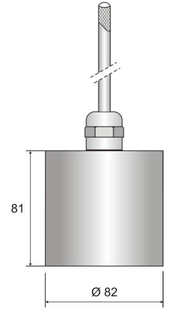
SET/OS2 dimensions
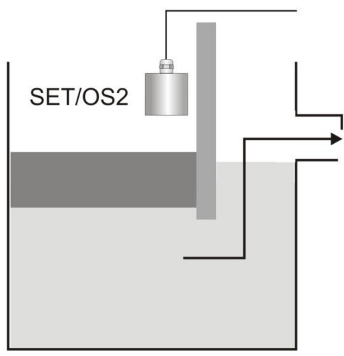
Application: pounding alarm
Connections & Installations
SET/OS2 is equipped with a shielded 3-wire cable. The wires 1 and 2 shall be connected to the corresponding connectors (1 = +, 2 = -) in the control unit. Wire 3 shall be connected to the equipotential ground together with the shield of the cable.
Please refer also to the installation instructions of the control unit. The cable can be shortened or, when the control unit is located further away from the sensor, the cable can be extended with the junction box. The sensor can be installed to hang up in the air from the top of the tank to generate the high-level alarm, or immersed into the liquid to generate the low-level or oil/water alarm.
When installing the sensor into an explosion-hazardous area (0/1/2), the following standards need to be followed: EN IEC 60079- 25 Electrical apparatus for potentially explosive atmospheres – Intrinsically safe electrical system “i, EN IEC 60079-14 Electrical apparatus for explosive gas atmospheres.
The sensor shall not be installed in a space where caustic vapour, gas, or liquid, such as aromatic and chlorinated hydrocarbons or strong alkalis or acids, can damage the equipment.
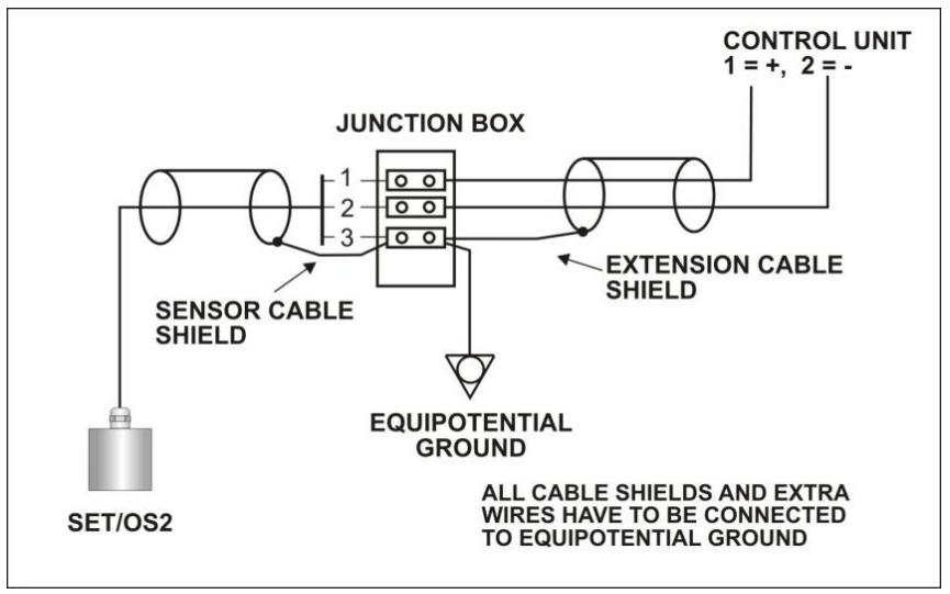
Wiring example
Switching Point
- Turn the SENSE trimmer of the control unit to the extreme clockwise position.
- Immerse the sensor in the liquid to be measured.
- When 30-40 mm of the sensor is immersed in liquid, the control unit should operate.
- If it doesn’t, adjust the SENSE trimmer slowly counterclockwise until the desired switching point is reached.
- As for conductive liquids (water, etc.), the switching point should be achieved when 10-20 mm of the sensor is immersed.
- Check the function by lifting and immersing the sensor a few times into the liquid.
If the sensor is located in a hazardous area, an Ex-classified multimeter must be used and the Ex-standards mentioned in the chapter.
Repair & Service
Make sure that the sensor is properly connected to the control unit. The voltage between connectors 1 and 2 in the control unit should be 10,5…12V. If the voltage is correct, measure the sensor current as follows.
- Connect the ammeter according to the picture below by disconnecting the conducting wire 1from the central unit.
- Measure the current.
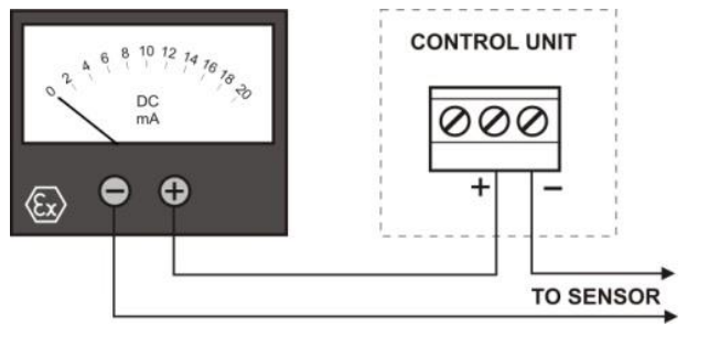
Measuring the sensor current
Sensor current in different conditions.

The sensors must always be cleaned down and tested Labkotec SETOS2 Liquid Level Detection Sensor when emptying the tank or separator and when carrying out annual maintenance. For cleaning, a mild detergent (e.g., washing-up liquid) and a scrubbing brush can be used. Service, inspection, and repair of Ex-apparatus needs to be done according to standards EN IEC 60079-17 and EN IEC 60079-19.
Technical Data
EU Declaration of Confirmty
We hereby declare that the product named below has been designed to comply with the relevant requirements of the referenced directives and standards.
Product: Level sensor SET/OS2, SET/OSK2
Manufacturer Labkotec Oy Myllyhaantie 6 FI-33960 Pirkkala Finland
Directives: The product is in accordance with the following EU Directives: 2014/30/EU Electromagnetic Compatibility Directive (EMC). 2014/34/EU Equipment for Potentially Explosive Atmospheres Directive (ATEX). 2011/65/EU Restriction of Hazardous Substances Directive (RoHS)
Standards: The following standards were applied:
EMC: EN IEC 61000-6-2:2019, EN IEC 61000-6-3:2021
ATEX: EN IEC 60079-0:2018, EN 60079-11:2012
EC-type examination certificate: VTT 03 ATEX 009X.
Notified Body: VTT Expert Services Ltd, Notified Body number 0537. The revised harmonised standards have been compared to the previous standard versions used in the original type certification, and no changes in the “state of the art” of the equipment.
RoHS: EN IEC 63000:2018 The product has been CE-marked since 2003.
Signature: This declaration of conformity is issued under the sole responsibility of the manufacturer. Signed for and on behalf of Labkotec Oy.
Customer Service
- E-mail: labkonet@labkotec.fi
- Tel: +358 29 006 6066.
- Address: Myllyhaantie 6, FI-33960 Pirkkala, Finland
© 2025 Labkotec.fi.
FAQs
What is the Labkotec SETOS2 sensor used for?
Designed mainly for oil separators, grease traps, and other applications where detecting the presence of liquids—especially hydrocarbons—is essential for environmental safety and compliance, the SETOS2 is a small and dependable liquid level detection sensor.
What types of liquids can the SETOS2 detect?
Depending on the application, the SETOS2 is designed to detect conductive liquids like water and non-conductive liquids like oil. It works very well for locating oil layers in separators.
How is the SETOS2 sensor powered?
A 24 VDC or 230 VAC supply is normally used to power the SETOS2, depending on the control unit to which it is linked. For the precise voltage parameters, consult the sensor label or user manual.
Does the SETOS2 require a control unit to operate?
Indeed. The SETOS2 sensor is made to function with Labkotec control units, such as SET/OSK. The control unit decodes the signals from the sensor and sets off the appropriate alarms or actions.
Can I connect the SETOS2 directly to a PLC or SCADA system?
Not right away. In order to interact with a PLC or SCADA system, the sensor needs to be attached to a Labkotec controller, which offers digital outputs or a standard relay.
Does the sensor require calibration?
For common uses, the SETOS2 is factory-calibrated. Although it is typically not necessary to manually calibrate, always check the operation after installation, particularly when using non-standard liquids.
How do I clean or maintain the SETOS2 sensor?
Periodic examination and cleaning are essential, especially in greasy or oily situations. Avoid using harsh chemicals or abrasive instruments that could harm the sensor body; instead, use a gentle brush and mild detergent.


