


 Seeed Studio RTU RS485 Light Intensity Sensor
Introduction
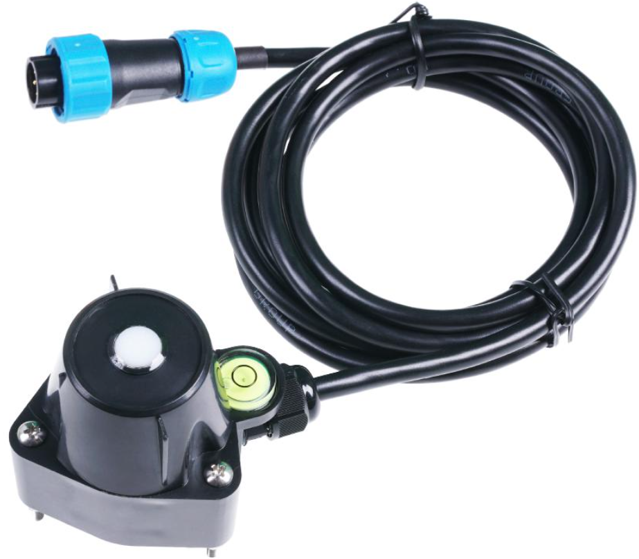
The Seeed Studio RTU RS485 Light Intensity Sensor, also known as the S-Light-01 ambient light sensor, measures ambient illuminance with high accuracy and consistency. It is widely used in scientific research, solar power, greenhouse, and weather station applications.
- Measurement range to 200000lux
- Output interface with RS-485, Voltage
- Level indicator and spring-loaded for installation
- Waterproof to IP66 can be used outdoors directly
- High accuracy and consistency with excellent stability
- Reverse power protection and Built-in TVS/ESD protection
Specifications
Below are the detailed specifications for the Seeed Studio RTU RS485 Light Intensity Sensor, including its power supply, measurement range, and installation requirements.
| Output Interface | Analog Voltage 0-2V (Output resistance ~0ohm) | RS485 Modbus-RTU |
| Power Supply | 3.9-30V/DC | 3.9-30V/DC |
| Power
Consumption |
7mA@24V DC | 7mA@24V DC |
| Illuminance Range | Range:0~200000 Lux, Accuracy:±6% , Resolution:1lux | |
| Direction Error | 30°±3%,60°±6%,80°±24%(Cosine Characteristics) | |
| IP Ratings | IP66 | |
| Operating
Temperature |
-40~85°C | |
| Installation | Screw hole * 3 | |
| Cable Length | 2 meters | |
| Dimension | 75*55*58mm | |
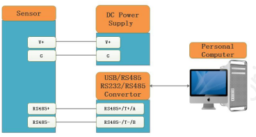
Wiring

All RS485 communication parameters for the Seeed Studio RTU RS485 Light Intensity Sensor (Modbus Slave Address, baud rate, parity, databits, stopbits) are set in internal registers. For connecting to microcontrollers like the Seeed Studio XIAO ESP32S3 series, ensure proper wiring and power supply. The factory setting is ADDRESS=1, BAUDRATE=9600bps, PARITY=NONE, DATABITS=8bits, STOPBITS=1bit. Sometimes you may forget the communication settings.
In this case, you can open the shield module and press the SET button for more than 3 seconds. The communication parameters are reset to factory settings, allowing the Seeed Studio RTU RS485 Light Intensity Sensor to communicate using default settings. Please re-power up the sensor to make the new settings effective.
Dimension
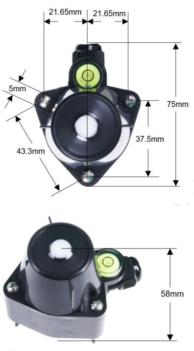
Installation
Adjust the screw and check the horizontal bubble to ensure the Seeed Studio RTU RS485 Light Intensity Sensor is properly and horizontally installed.
Output Signal Conversion
| Output
Interface |
Parameters Range | Conversion Formula |
| Analog Voltage Output 0-2V | ILLU: 0-200000 lux | ILLU=RANGE* VLOTAGE/2.00.When RANGE=2000 lux and VOLTEGE=1.0V,then ILLU =2000*1.00/2.00=1000
lux |
| RS485
Modbus-RTU |
ILLU: 0-200000 lux | ILLU =(32-Bits REGISTER VALUE).When REGISTER
VALUE=1000,then ILLU= 1000 lux |
Modbus Protocol
- Modbus Protocol is widely used to establish master-slave communication between intelligent devices or sensors. The Seeed Studio RTU RS485 Light Intensity Sensor uses this protocol to transmit data accurately. A MODBUS message sent from a master to a slave contains the address of theslave, the function code (e.g., ‘read register’ or ‘write register’), the data, and a checksum sum (LRC or CRC).
- The sensor is an RS-485 interface with the Modbus protocol. The default serial communication settingsisslaveaddress 1, Modbus RTU, 9600bps, 8 data bits, and 1 stop bit. All communication settings can be changed with a Modbus command and take effect after re-powering up the sensor.
- The following Modbus function codes are supported by the sensor.
- Modbus Function Code 0x03is used for reading holding registers
- Modbus Function Code 0x04: used for reading input register.
- Modbus Function Code 0x06 is used for writing a single holding register.
- Modbus Function Code 0x10: used for writing multiple holding registers.
Registeration
| Parameters | Register Addr. (HEX/DEC) | Data Type | Modbus Function Code(DEC
) |
Range and Comments | Default Value |
| ILLUMINANCE
HIGH 16 Bits |
0x0000 /0 | UINT16
RO |
3/4 | 0-200000 for
0-200000lux |
N/A |
| ILLUMINANCE
LOW 16 Bits |
0x0001 /1 | UINT16
RO |
3/4 | ||
| STATUS | 0x0002 /2 | UINT16 RO | 3/4 | BIT15-BIT2: Reserved BIT1: Sensor Error
BIT0: Over Range |
N/A |
| RESERVED | 0x0003 /3 | UINT16
RO |
3/4 | 0 | 0 |
| RESERVED | 0x0004 /4 | UINT16
RO |
3/4 | 0 | 0 |
| RESERVED | 0x0004 /5 | UINT16
RO |
3/4 | 0 | 0 |
| SLAVEADDRESS | 0x0200 /512 | UINT16
R/W |
3/6/16 | 0-255 | 1 |
| BAUDRATE | 0x0201 /513 | UINT16
R/W |
3/6/16 | 0-6
0:1200bps 1:2400bps 2:4800bps 3:9600bps 4:19200bps 5:38400bps |
3:9600bps |
| PROTOCOL | 0x0202 /514 | UINT16
R/W |
3/6/16 | 0
0:Modbus RTU |
0:Modbus RTU |
| PARITY | 0x0203 /515 | UINT16
R/W |
3/6/16 | 0-2
0:None 1:Even 2:Odd |
0:None Parity |
| DATABITS | 0x0204 /516 | UINT16
R/W |
3/6/16 | 1
1:8 databits |
1:8
databits |
| STOPBITS | 0x0205 /517 | UINT16 | 3/6/16 | 0-1 | 0:1 stopbit |
| R/W | 0:1 stopbit
1:2 stopbits |
||||
| RESPONSEDELAY | 0x0206 /518 | UINT16
R/W |
3/6/16 | 0-255 for 0-2550
milliseconds |
0 |
| ACTIVEOUTPUTINT ERVAL | 0x0207 /519 | UINT16
R/W |
3/6/16 | 0-255 for 0-255
seconds. |
0 |
Modbus Register Detail Description
| ILLUMINANCE – HIGH 16 Bits
ILLUMINANCE – LOW 16 Bits |
||
| Data Range | 0-200000 for 0-200000 lux | Default: N/A |
| Power Down
Save |
N/A | |
Example
When REGISTER(HIGH 16 Bits) = 0x0003 (HEX format) and REGISTER(HIGH16Bits)=0x0D40 (HEX format), then VALUE=(0x0003 *65536+0x0D40) = 200000lux
| STATUS | ||
| Data Range | BIT15-BIT2: Reserved, always 0 BIT1: Bit set when sensor error
BIT0: Bit set when overrange |
Default: N/A |
| Power Down
Save |
N/A | |
Sensor Status
| SLAVEADDRESS — Modbus Slave Address | ||
| Data Range | 0-255 | Default: 1 or 13 |
| Power Down
Save |
YES |
|
| BAUDRATE — Serial Comm Baudrate | ||
| Data Range | 0-5
0:1200bps 1:2400bps 2:4800bps 3:9600bps 4:19200bps |
Default: 3 |
Please re-power on the sensor to take effect after setting.
| PROTOCOL — Serial Comm Protocol | ||
| Data Range | 0
0:Modbus RTU |
Default: 0 |
| Power Down
Save |
YES | |
| PARITY — Serial Comm Parity | ||
| Data Range | 0-2 0:NONE 1:EVEN 2:ODD |
Default: 0 |
| Power Down
Save |
YES | |
Please re-power on the sensor to take effect after setting.
| DATABITS — Serial Comm Databits | ||
| Data Range | 1
1:8 databits |
Default: 1 |
| Power Down
Save |
YES | |
| STOPBITS — Serial Comm Stopbits | ||
| Data Range | 0-1
0:1 stopbit 1:2 stopbits |
Default: 0 |
| Power Down
Save |
YES | |
| RESPONSEDELAY — Serial Comm Response Delay | ||
| Data Range | 0-255 for 0-2550 milliseconds, 0 for disabled | Default: 0 |
| Power Down
Save |
YES | |
Example
When set to 5 and receive a request from the master device, then the sensor will delay 5*10ms=50ms, then respond to the master.
| ACTIVEOUTPUTINTERVAL — Serial Comm Active Output Interval time | ||
| Data Range | 0-255 for 0-255 seconds, 0 for disabled | Default: 0 |
| Power Down
Save |
YES | |
Modbus Function Code
For the description below, data starting with 0X/0x means that it’s in HEX format.
Function Code 3 Protocol
- Master Request: AA 03 RRRR NNNN CCCC
| AA | 1 byte | Slave Address,0-255 |
| 0x03 | 1 byte | Function Code 3 |
| RRRR | 2 byte | Starting Register Addr |
| NNNN | 2 byte | Quantity of Register to read |
| CCCC | 2 byte | CRC CHECKSUM |
Slave Response: AA 03 MM VV0 VV1 VV2 VV3… CCCC
| AA | 1 byte | Slave Address,0-255 |
| 0x03 | 1 byte | Function Code 3 |
| MM | 1 byte | Register Data Byte Count |
| VV0,VV1 | 2 byte | Register Value (High8bits first) |
| VV2,VV3 | 2 byte | Register Value (High8bits first) |
| … | … | Register Value (High8bits first) |
| CCCC | 2 byte | CRC CHECKSUM |
Master Request:01 03 0200 0002 C5B3
| Slave Addr. | 1 byte | 0x01 |
| Function Code | 1 byte | 0x03 |
| Starting Register
Addr. |
2 byte | 0x0200 |
| Quantity of
Register to read |
2 byte | 0x0002 |
| Checksum | 2 byte | 0xC5B3 |
Slave Response:01 03 04 00 01 00 03 EB F2
| Slave Addr. | 1 byte | 0x01 |
| Function Code | 1 byte | 0x03 |
| Register Data Byte
Count |
1 byte | 0x04 |
| Register Value:
Address |
2 byte | 0x00(HIGH 8 Bits) |
| 0x01(LOW8 Bits) | ||
| Register Value:
Baudrate |
2 byte | 0x00(HIGH 8 Bits) |
| 0x03(LOW8 Bits) | ||
| Checksum | 2 byte | 0xEBF2 |
Function Code 4 Protocol Example
Master Request: AA 04 RRRR NNNN CCCC
| AA | 1 byte | Slave Address,0-255 |
| 0x04 | 1 byte | Function Code 4 |
| RRRR | 2 byte | Starting Register Addr |
| NNNN | 2 byte | Quantity of Register to read |
| CCCC | 2 byte | CRC CHECKSUM |
Slave Response: AA 04 MM VV0 VV1 VV2 VV3… CCCC
| AA | 1 byte | Slave Address,0-255 |
| 0x04 | 1 byte | Function Code 4 |
| MM | 1 byte | Register Data Byte Count |
| VV0,VV1 | 2 byte | Register Value (High8bits first) |
| VV2,VV3 | 2 byte | Register Value (High8bits first) |
| … | … | Register Value (High8bits first) |
| CCCC | 2 byte | CRC CHECKSUM |
Master Request: 01 04 00 00 00 02 71 CB
| Slave Addr. | 1 byte | 0x01 |
| Function Code | 1 byte | 0x04 |
| Starting Register | 2 byte | 0x0000 |
| Addr. | ||
| Quantity of
Register to read |
2 byte | 0x0002 |
| Checksum | 2 byte | 0x71CB |
Slave Response: 01 04 04 0000 004D 3BB1
| Slave Addr. | 1 byte | 0x01 |
| Function Code | 1 byte | 0x04 |
| Register Data Byte
Count |
1 byte | 0x04 |
| Register Value:
Illuminance high 16 bits |
2 byte | 0x00(HIGH 8 Bits) |
| 0x00(LOW8 Bits) | ||
| Register Value:
Illuminance low 16 bits |
2 byte | 0x00(HIGH 8 Bits) |
| 0x4D(LOW8 Bits) | ||
| Checksum | 2 byte | 0x3BB1 |
Function Code 6 Protocol Example
Master Request: AA 06 RRRR VVVV CCCC
| AA | 1 byte | Slave Address,0-255 |
| 0x06 | 1 byte | Function Code 6 |
| RRRR | 2 byte | Register Addr (High8bits first) |
| VVVV | 2 byte | Register Value (High8bits first) |
| CCCC | 2 byte | CRC CHECKSUM |
Slave Response: AA 06 RRRR VVVV CCCC
| AA | 1 byte | Slave Address,0-255 |
| 0x06 | 1 byte | Function Code 6 |
| RRRR | 2 byte | Register Addr (High8bits first) |
| VVVV | 2 byte | Register Value (High8bits first) |
| CCCC | 2 byte | CRC CHECKSUM |
Master Request: 01 06 0200 0002 09B3
| Slave Addr. | 1 byte | 0x01 |
| Function Code | 1 byte | 0x06 |
| Register Addr. | 2 byte | 0x0200 |
| Register Value | 2 byte | 0x0002 |
| Checksum | 2 byte | 0x09B3 |
Slave Response: 01 06 0200 0002 09B3
| Slave Addr. | 1 byte | 0x01 |
| Function Code | 1 byte | 0x06 |
| Register Addr. | 2 byte | 0x0200 |
| Register Value | 2 byte | 0x0002 |
| Checksum | 2 byte | 0x09B3 |
Function Code 16 Protocol Example
Master Request: AA 10 RRRR NNNN MM VVVV1 VVVV2 …CCCC
| AA | 1 byte | Slave Address,0-255 |
| 0x10 | 1 byte | Function Code 0x10 |
| RRRR | 2 byte | Starting Register Addr |
| NNNN | 2 byte | Quantity of Register to write |
| MM | 1 byte | Register Data Byte Count |
| VVVV1 | 2 byte | Register Value(High8bits first) |
| VVVV2 | 2 byte | Register Value(High8bits first) |
| … | … | Register Value(High8bits first) |
| CCCC | 2 byte | CRC CHECKSUM |
Slave Response: AA 10 RRRR NNNN CCCC
| AA | 1 byte | Slave Address,0-255 |
| 0x10 | 1 byte | Function Code 0x10 |
| RRRR | 2 byte | Starting Register Addr |
| NNNN | 2 byte | Quantity of Register to write |
| CCCC | 2 byte | CRC CHECKSUM |
Example
Write Register 0x0200-0x0201,that is set slave address to 1, andbaudrateto19200bp.
Master Request:01 10 0200 0002 04 0001 0004 BACC
| 0x01 | 1 byte | Slave Addr. |
| 0x10(HEX) | 1 byte | Function Code 0x10 |
| 0x0200 | 2 byte | Starting Register Addr |
| 0x0002 | 2 byte | Quantity of Register to write |
| 0x04 | 1 byte | Register Data Byte Count |
| 0x0001 | 2 byte | Register Value: Slave Address 1 |
| 0x0004 | 2 byte | Register Value: Baudrate 19200bps |
| 0xBACC | 2 byte | CRC CHECKSUM |
Salve Response:01 10 0200 0002 4070Software Configuration Utility
| 0x01 | 1 byte | Slave Addr. |
| 0x10(HEX) | 1 byte | Function Code 0x10 |
| 0x0200 | 2 byte | Starting Register Addr(High8bits first) |
| 0x0002 | 2 byte | Quantity of Register to write(High8bits first) |
| 0x4070 | 2 byte | CRC CHECKSUM |
Software Configuration Utility
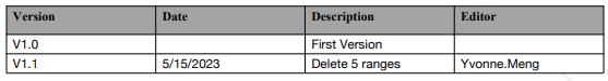
Document version
Customer Support
- Website: www.seeedstudio.com
- Ph: +86-0755-86095676
2008-2025 Seeed Technology Co., Ltd. All rights reserved.
2 Comments
Pingback: Seeed Studio BC01 BLE SenseCap Tracker | Setup & User Manual
Pingback: Seeed Studio J3011 ReComputer Edge AI Device | Specs & Setup