


Makita RT0702C 6mm Electric Trimmer

Safety Instructions
Read all safety warnings, instructions, illustrations, and specifications provided with this power tool. Failure to follow all instructions listed below may result in electric shock, fire, and/or serious injury.
- Keep the work area clean and well-lit. Cluttered or dark areas invite accidents.
- Keep children and bystanders away while operating a power tool.
- Power tool plugs must match the outlet. Never modify the plug in any way.
- Do not use any adapter plugs with earthed (grounded) power tools.
- Unmodified plugs and matching outlets will reduce the risk of electric shock.
- There is an increased risk of electric shock if your body is earthed or grounded.
- Do not expose power tools to rain or wet conditions.
- Water entering a power tool will increase the risk of electric shock.
- Do not abuse the cord. Never use the cord for carrying, pulling, or unplugging the power tool.
- Keep the cord away from heat, oil, sharp edges, or moving parts.
- Damaged or entangled cords increase the risk of electric shock.k
- When operating a power tool outdoors, use an extension cord suitable for outdoor use.
- Use of a cord suitable for outdoor use reduces the risk of electric shock.
- Power tools can produce electromagnetic fields (EMF) that are not harmful to the user.
- Stay alert, watch what you are doing, and use common sense when operating a power tool.
- Do not use a power tool while you are tired or under the influence of drugs, alcohol, or medication.
- A moment of inattention while operating power tools may result in serious personal injury.
- Use personal protective equipment. Always wear eye protection.
Use & Care
- Do not force the power tool. Use the correct power tool for your application.
- The correct power tool will do the job better and safer at the rate for which it was designed.
- Do not use the power tool if the switch does not turn it on and off.
- Any power tool that cannot be controlled with the switch is dangerous and must be repaired.
- Such preventive safety measures reduce the risk of accidentally starting the power tool.
- Power tools are dangerous in the hands of untrained users.
- If damaged, have the power tool repaired before use.
- Many accidents are caused by poorly maintained power tools.
- Keep cutting tools sharp and clean.
- Keep handles and grasping surfaces dry, clean, a nd free from oil and grease.
- When using the tool, do not wear cloth work gloves, which may get entangled.
- The entanglement of cloth work gloves in the moving parts may result in personal injury.
Service
- Have your power tool serviced by a qualified repair person using only identical replacement parts.
- This will ensure that the safety of the power tool is maintained.
- Follow the instructions for lubricating and changing accessories.
- Never service damaged battery packs.
- Service of battery packs should only be performed by the manufacturer or authorised service providers. Do not modify or attempt to repair the appliance or the battery pack except as indicated in the instructions for use and care.
Intended Use
The tool is intended for flush trimming and profiling of wood, plastic, and similar materials.
Power supply
The tool should be connected only to a power supply at the same voltage as indicated on the nameplate, and can be operated only on a single-phase AC supply. They are double-insulated and can, therefore, also be used from sockets without an earth wire.
Noise
The typical A-weighted noise level determined according to EN62841-2-17: Sound pressure level (LpA): 82 dB(A), Sound power level (LWA): 93 dB (A), Uncertainty (K) : 3 dB(A)
Vibration
The vibration total value (tri-axial vector sum) determined according to EN62841-2-17: Work mode: rotation without load Vibration emission (ah): 2.5 m/s2 or less Uncertainty (K): 1.5 m/s2
Functional Description
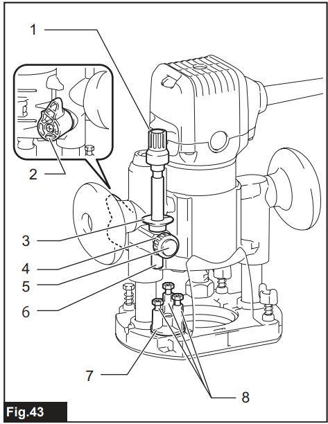
Adjusting the trimmer bit protrusion
To adjust the bit protrusion, open the locking lever and move the base up or down as desired by turning the adjusting screw. After adjusting, close the locking lever firmly to secure the base.
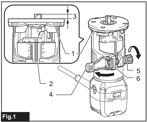
- Base
- Scale
- Bit protrusion
- Locking lever
- Adjusting screw
- Hex nut
- Switch
Electronic function
The tool is equipped with electronic functions for easy operation.
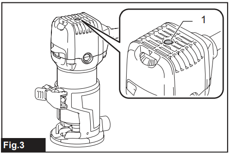
Indication lamp
The indication lamp lights up green when the tool is plugged. If the indication lamp does not light up, the mains cord or the controller may be defective. The indication lamp is lit, but the tool does not start. Even if the tool is switched on, the carbon brushes may be worn out, or the controller, the motor, or the ON/OFF switch may be defective.
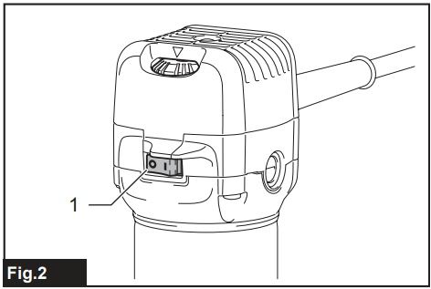
Unintentional restart proof
The tool does not start with the I side of the switch pressed, even when the tool is plugged. At this time, the indication lamp blinks in red and shows that the unintentional restart proof device is in function. To cancel the unintentional restart proof, press the O side of the switch.
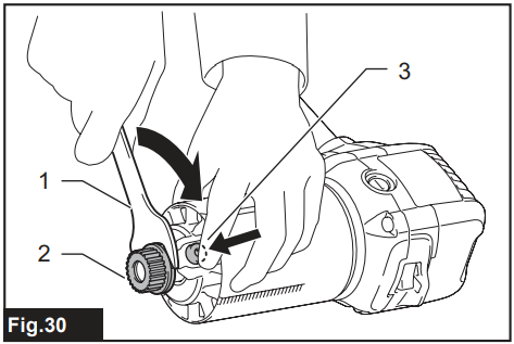
Constant speed control
Electronic speed control for obtaining a constant speed. Possible to get a fine finish, because the rotating speed is kept constant even under the loaded condition. The tool speed can be changed by turning the speed adjusting dial to a given number setting from 1 to 6.
 Speed Adjusting Dial
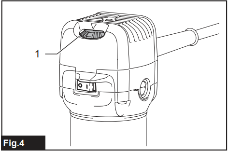
Higher speed is obtained when the speed adjusting dial is turned in the direction of number 6. And a lower speed is obtained when it is turned in the direction of number 1. This allows the ideal speed to be selected for optimum material processing, i.e., the speed can be correctly adjusted to suit the material and bit diameter. Refer to the table for the relationship between the number settings on the dial and the approximate tool speed.
| Number | min-1 |
| 1 | 10,000 |
| 2 | 12,000 |
| 3 | 17,000 |
| 4 | 22,000 |
| 5 | 27,000 |
| 6 | 34,000 |
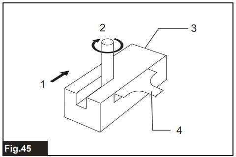
With Two Wrenches
Insert the trimmer bit all the way into the collet cone and tighten the collet nut securely with one wrench while holding the neck with the other wrench.

- Tighten
- Loosen
- Neck
- Collet nut
One Wrench
Insert the trimmer bit all the way into the collet cone and tighten the collet nut securely with the wrench while pressing the shaft lock.
- Tighten
- Loosen
- Shaft lock
- Collet nut
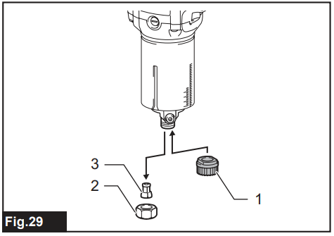
Changing the Collet Cone
- Loosen the collet nut and remove it.
- Replace the installed collet cone with the desired collet cone.
- Reinstall the collet nut.
- Collet cone
- Collet nut
Operation
For the base
- Dust nozzle
- Thumb screw
- Base
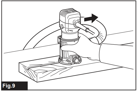
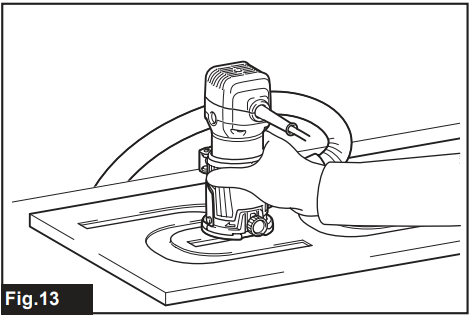
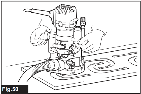
- Set the base on the workpiece to be cut without the trimmer bit making any contact.
- Turn the tool on and wait until the trimmer bit attains full speed.
- Move the tool forward over the workpiece surface, keeping the base flush and advancing smoothly until the cutting is complete.
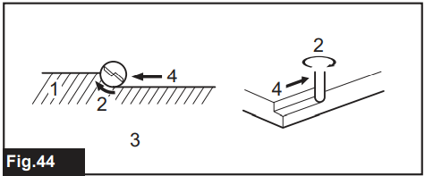
When doing edge cutting, the workpiece surface should be on the left side of the trimmer bit in the feed direction.
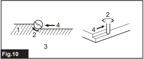
- Workpiece
- Bit revolving direction
- View from the top of the tool 4. Feed direction
- Feed direction
- Bit revolving direction
- Workpiece
- Straight guide
Base (resin)
Optional accessory: You can use the base (resin) as an optional accessory, as shown in the figure.
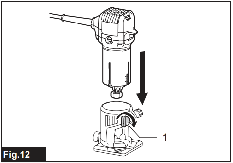
Clamping screw
Place the tool onto the base (resin) and tighten the clamping screw at the desired protrusion of the trimmer bit. For the operation procedures, refer to the operation for the base.
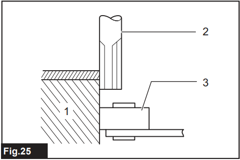
Templet guide
Optional accessor:y: The template guide provides a sleeve through which the trimmer bit passes, allowing use of the trimmer with template patterns.
- Loosen the screws and remove the base protector.
- Base protector
- Screws

- Trimmer bit
- Base
- Base protector
- Templet
- Workpiece
- Templet guide
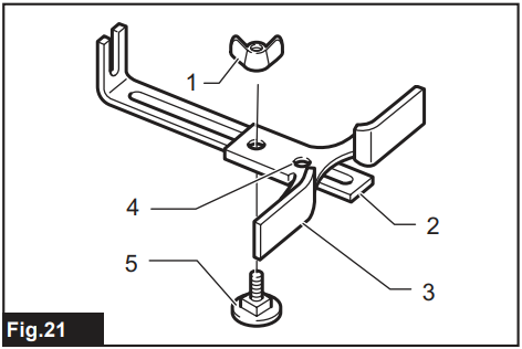
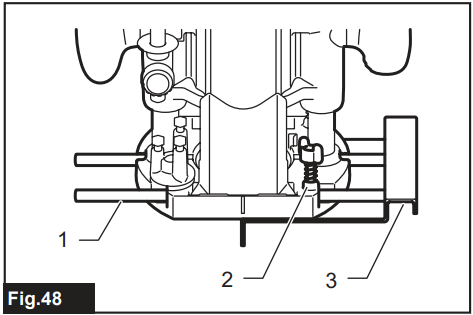
Straight Guide
Optional accessory: The straight guide is effectively used for straight cuts when chamfering or grooving.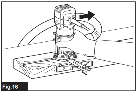
Attach the guide plate to the straight guide with the bolt and the wing nut.

- Bolt
- Guide plate
- Straight guide
- Wing nut
- Clamping screw
- Straight guide
- Wing nut
- Base
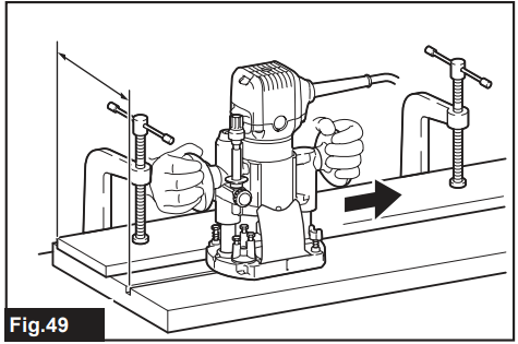
Circular Work
Circular work may be accomplished if you assemble the straight guide and guide plate as shown in the figures. Min. and max. Radius of circles to be cut (distance between the centre of the circle and the centre of the trimmer bit) is as follows: Min.: 70 mm, Max.: 221 mm. For cutting circles between 70 mm and 121 mm in radius
- Wing nut
- Guide plate
- Straight guide
- Center hole
- Bolt
- Wing nut
- Guide plate
- Straight guide
- Center hole
- Bolt

- Nail
- Center hole
- Straight guide

- Nail
- Center hole
- Straight guide

- Adjusting screw
- Guide holder
- Trimmer guide
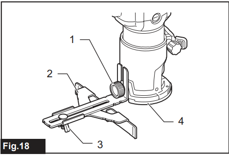
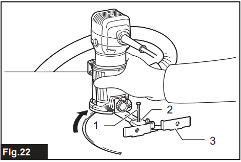
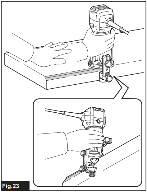
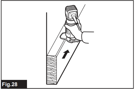
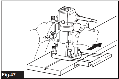
Tilt Base
Optional accessory: The tilt base is used for trimming the edge of a laminate sheet or similar materials. The tilt base is convenient for chamfering.
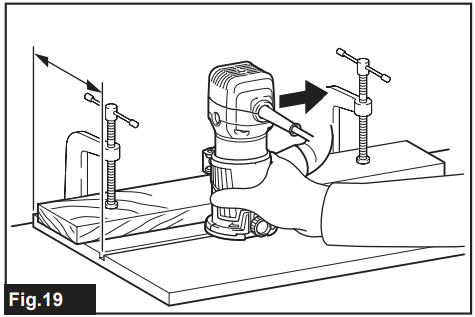
- Place the tool onto the tilt base, loosen the clamping screws, and tilt the tool at the desired angle.
- Firmly clamp a straight board to the workpiece and use it as a guide against the tilt base. Feed the tool in the direction of the arrow.

- Clamping screws
- Locking lever
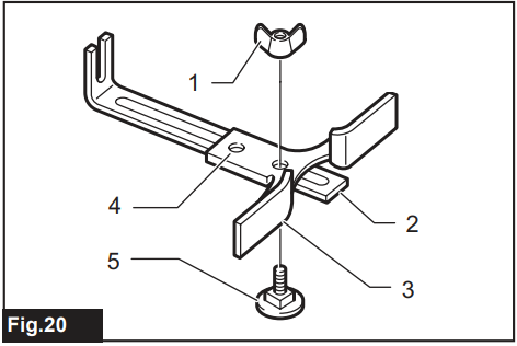
Using the tilt base protector with the base
The tilt base protector (square) removed from the tilt base can be mounted on the base. The shape of the base protector can be changed from round to square.
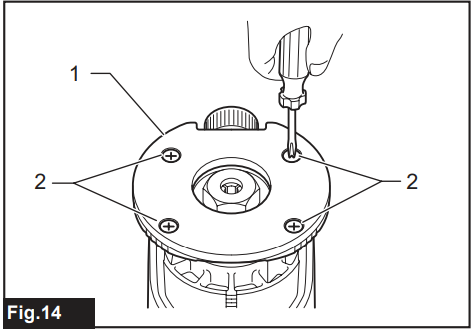
- Remove the tilt base protector from the tilt base by loosening and removing the four screws.
- Mount the tilt base protector on the base.
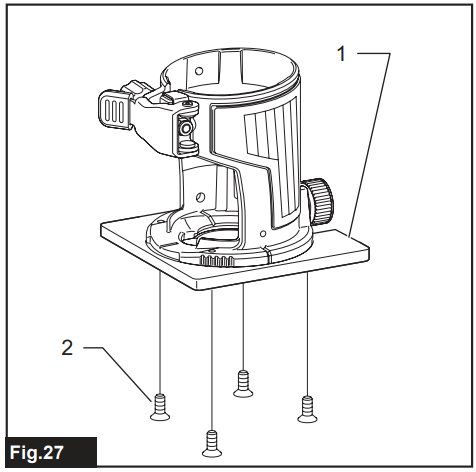
- Tilt base protector
- Screw
Offset Base
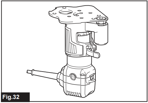
Optional accessory: The offset base is used for trimming the edge of a laminate sheet or similar materials. The offset base is convenient for work in a tight area.
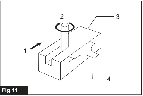
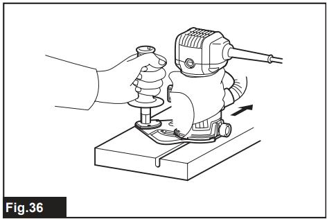
Using the Tool with the Offset Base
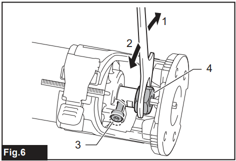
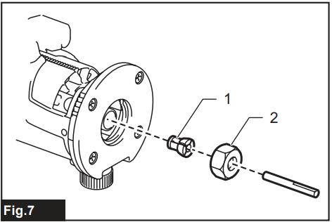
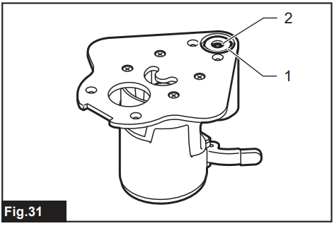
- Before installing the tool on the offset base, remove the collet nut and collet cone by loosening the collet nut.
- Pulley
- Collet nut
- Collet cone
- Wrench
- Pulley
- Shaft lock
- Collet nut
- Collet cone
 Pulley
- Belt
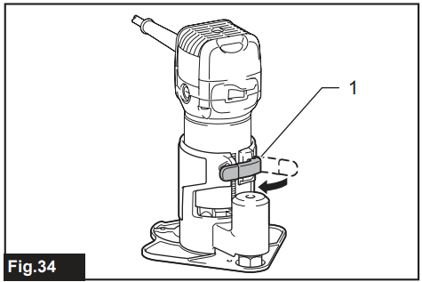
- Locking lever
- Wrench
- Hex wrench
- Trimmer bit
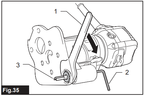
- Loosen the screws and remove the upper section from the offset base.
- Put aside the upper section of the offset base.
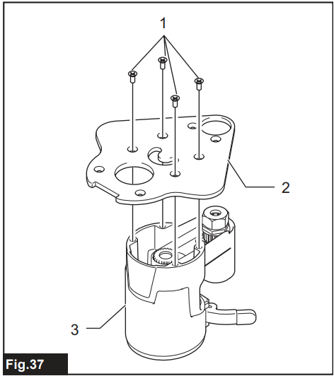
- Screws
- Offset base plate
- Upper section of the offset base
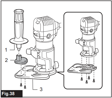
- Bar-type grip
- Grip attachment
- Offset base plate
- Screw
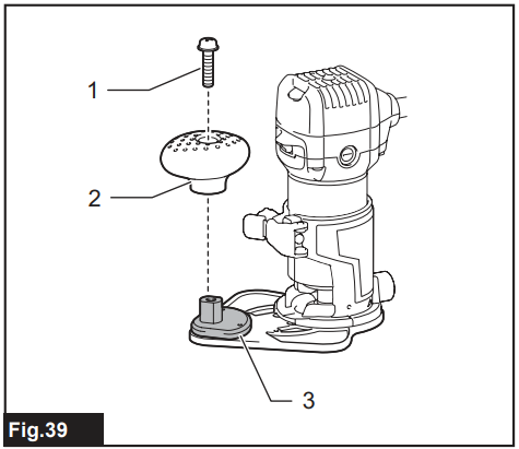
- Knob-type grip
- Grip attachment
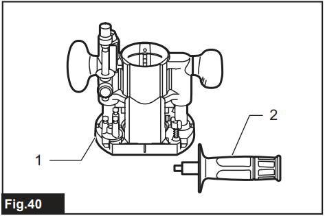
- Plunge base
- Bar-type grip
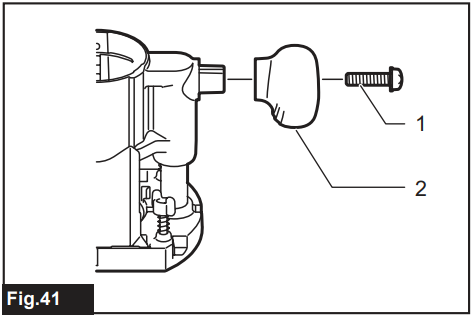
- Screw
- Knob-type grip
 Bar-type grip
- Adjusting knob
- Lock lever
- Depth pointer
- Stopper pole setting nut
- Fastfeed button
- Stopper pole
- Stopper block
- Adjusting a hex bolt
- Workpiece
- Bit revolving direction
- View from the top of the tool
- Feed direction
- Feed direction
- Bit revolving direction
- Workpiece
- Straight guide
 Bolt
Bolt- Guide holder
- Wing nut (A)
- Bolt
- Wing nut (B)
- Guide plate
- Straight guide
- Wing bolts
- Insert the guide bars into the holes in the plunge base.
- Guide bar
- Wing nut
- Straight guide
Templet Guide
Optional accessory: The template guide provides a sleeve through which the trimmer bit passes, allowing use of the trimmer with template patterns.
Loosen the screws on the tool base, insert the template, and then tighten the screws.
- Screw
- Base
- Templet guide
- Trimmer bit
- Base
- Base protector
- Templet
- Workpiece
- Templet guide
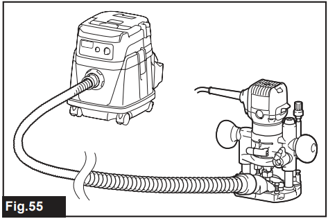
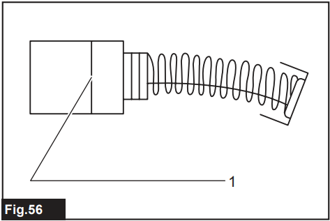
Dust Nozzle Sets
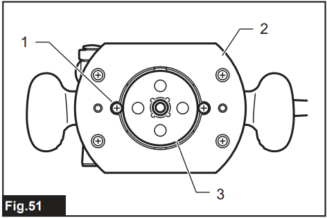
Use the dust nozzle for dust extraction. For the base Install the dust nozzle on the tool base using the thumb screw.
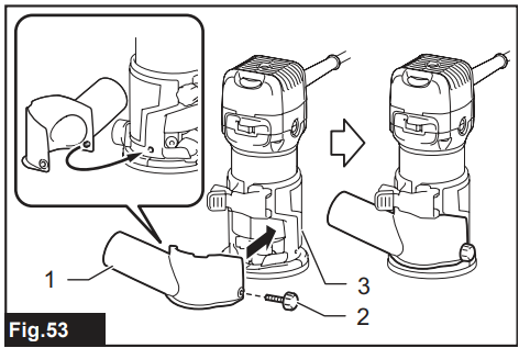
- Dust nozzle
- Thumb screw
- Base
For the Plunge Base
- Install the dust nozzle on the plunge base using the thumb screw so that the protrusion on the dust nozzle fit to the notch in the plunge base
 Dust nozzle
- Thumb screw
- Plunge base
To maintain product SAFETY and RELIABILITY, repairs, any other maintenance, or adjustment should be performed by Makita Authorised or Factory Service Centres, always using Makita replacement parts.
Replacing Carbon Brushes
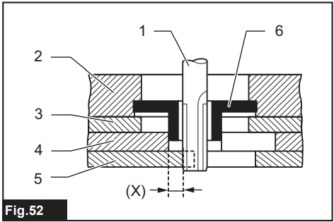
Limit Mark
Check the carbon brushes regularly. Replace them when they wear down to the limit mark. Keep the carbon brushes clean and free to slip in the holders. Both carbon brushes should be replaced at the same time. Use only identical carbon brushes.
- Use a screwdriver to remove the brush holder caps.
- Take out the worn carbon brushes, insert the new ones, and secure the brush holder caps.
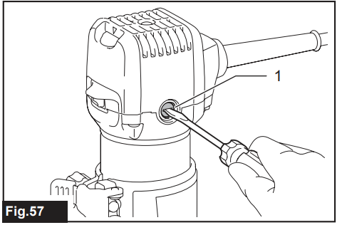
Brush Holder Cap
If you need any assistance for more details regarding these accessories, ask your local Makita Service Centre.
- Straight & groove forming bits
- Edge forming bits
- Laminate trimming bits
- Straight guide assembly
- Trimmer guide assembly
- Base assembly (resin)
- Tilt base assembly
- Plunge base assembly
- Offset base assembly
- Templet guide
- Collet cone
- Wrench
- Dust nozzle
- Guide rail
- Guide rail adapter set
- Straight guide with micro adjustment
- Side grip
- Grip attachment
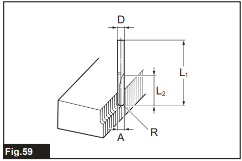
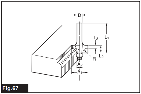
Trimmer Bits
Straight bit
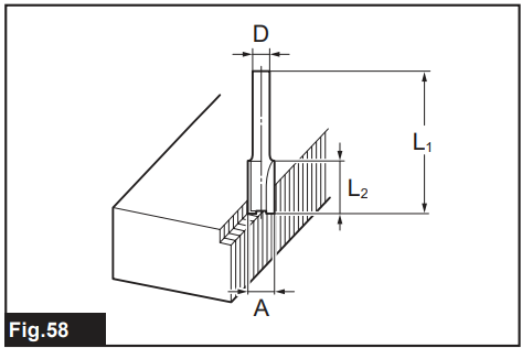
| D | A | L1 | L2 |
| 6 | 20 | 50 | 15 |
| 1/4″ | |||
| 8 | 8 | 60 | 25 |
| 6 | 50 | 18 | |
| 1/4″ | |||
| 6 | 6 | 50 | 18 |
| 1/4″ |
| D | A | L1 | L2 | R |
| 6 | 6 | 60 | 28 | 3 |
| 1/4″ |
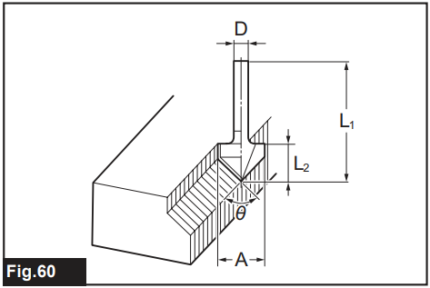
| D | A | L1 | L2 | θ |
| 1/4″ | 20 | 50 | 15 | 90° |
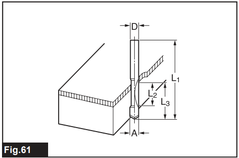
| D | A | L1 | L2 | L3 |
| 8 | 8 | 60 | 20 | 35 |
| 6 | 6 | 60 | 18 | 28 |
| 1/4″ |
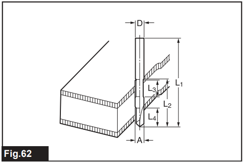
| D | A | L1 | L2 | L3 | L4 |
| 8 | 8 | 80 | 95 | 20 | 25 |
| 6 | 6 | 70 | 40 | 12 | 14 |
| 1/4″ |
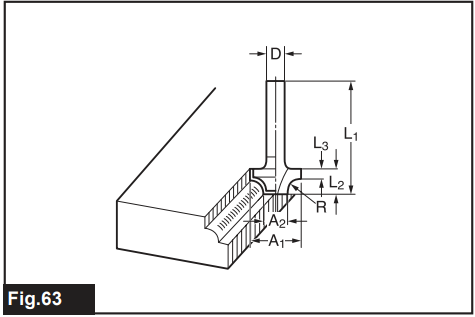
| D | A1 | A2 | L1 | L2 | L3 | R |
| 6 | 25 | 9 | 48 | 13 | 5 | 8 |
| 1/4″ | ||||||
| 6 | 20 | 8 | 45 | 10 | 4 | 4 |
| 1/4″ |
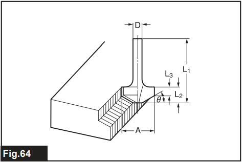
| D | A | L1 | L2 | L3 | θ |
| 6 | 23 | 46 | 11 | 6 | 30° |
| 6 | 20 | 50 | 13 | 5 | 45° |
| 6 | 20 | 49 | 14 | 2 | 60° |
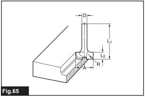
| D | A | L1 | L2 | R |
| 6 | 20 | 43 | 8 | 4 |
| 6 | 25 | 48 | 13 | 8 |
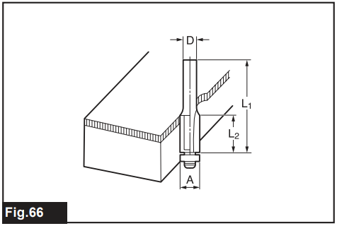
| D | A | L1 | L2 |
| 6 | 10 | 50 | 20 |
| 1/4″ |
| D | A1 | A2 | L1 | L2 | L3 | R |
| 6 | 15 | 8 | 37 | 7 | 3.5 | 3 |
| 6 | 21 | 8 | 40 | 10 | 3.5 | 6 |
| 1/4″ | 21 | 8 | 40 | 10 | 3.5 | 6 |
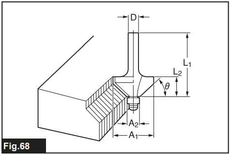
| D | A1 | A2 | L1 | L2 | θ |
| 6 | 26 | 8 | 42 | 12 | 45° |
| 1/4″ | |||||
| 6 | 20 | 8 | 41 | 11 | 60° |
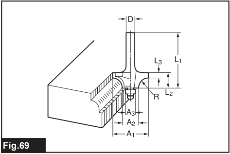
| D | A1 | A2 | A3 | L1 | L2 | L3 | R |
| 6 | 20 | 12 | 8 | 40 | 10 | 5.5 | 4 |
| 6 | 26 | 12 | 8 | 42 | 12 | 4.5 | 7 |
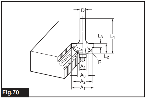
| D | A1 | A2 | A3 | A4 | L1 | L2 | L3 | R |
| 6 | 20 | 18 | 12 | 8 | 40 | 10 | 5.5 | 3 |
| 6 | 26 | 22 | 12 | 8 | 42 | 12 | 5 | 5 |
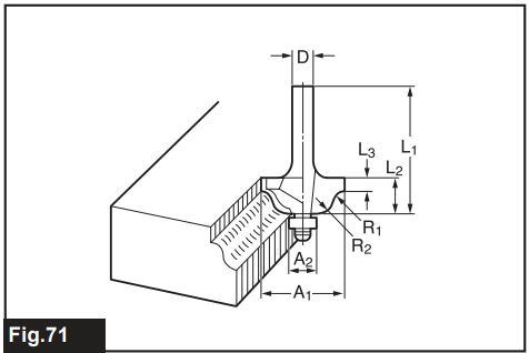
| D | A1 | A2 | L1 | L2 | L3 | R1 | R2 |
| 6 | 20 | 8 | 40 | 10 | 4.5 | 2.5 | 4.5 |
| 6 | 26 | 8 | 42 | 12 | 4.5 | 3 | 6 |
Specifications
| Model: | RT0702C |
| Collet chuck capacity | 6 mm, 8 mm, or 1/4″ |
| No load speed | 10,000 – 34,000 min-1 |
| Overall height | 210 mm |
| Net weight | 1.8 – 2.8 kg |
| Safety class | /II |
Limited Warranty
Please refer to the annexed warranty sheet for Makita products for the most current warranty terms applicable to this product. If the annexed warranty sheet is not available, refer to the warranty details set forth on the website below for your respective country.
- United States of America: www.makitatools.com
- Canada: www.makita.ca
- Other countries: www.makita.com
Customer Service
- Website: https://www.makitauk.com/
- Ph: 1-800-462-5482