Digital Projection E-Vision Laser 5900 Series Projector
Safety Instructions
- The unit is never to be operated if it is defective or if the cover or seal is damaged.
- No maintenance allowed by the end user. Do not open the cabinet.
- No service is allowed except by authorized personnel. Use only the power cable provided.
- Ensure that the power outlet includes a Ground connection, as this equipment MUST be earthed.
- Take care to prevent small objects such as paper or wire from falling into the projector.
- Do not expose the projector to rain or moisture, and do not place any liquids on top of the projector.
- Unplug before cleaning, and use a damp, not wet, cloth. Do not touch the power plug with wet hands.
- Do not touch the power plug during a thunderstorm. Do not stare into the beam.
- Handle the power cable carefully and avoid sharp bends. Do not use a damaged power cable.
- Do not view directly with optical instruments. Only allow use by responsible persons.
- Keep out of reach of children. This device is not a toy.
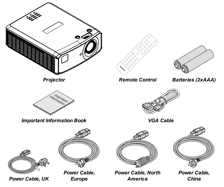
What’s in the Box
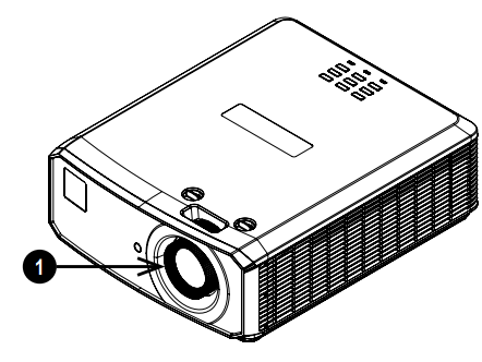
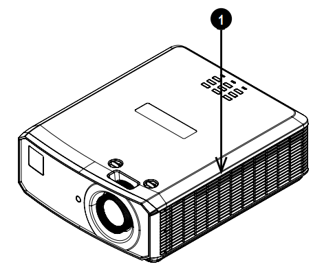
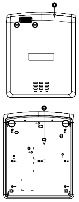
Location of Laser Aperture
- The laser aperture is located as indicated below.
Interlock Switches
- Interlock switches are installed at the main frame, inside the cover.
- These will power-off the system individually when activated.
- Will be activated when the top cover is removed.
Remote Control
- Power ON / OFF Turns power on and off.
- PC Select the Computer In input.
- HDMI Select and toggle the HDMI 1, HDMI 2, or DVI-D input.
- USB: There is no USB function on this projector.
- Video S Video Select the Video input. There is no S Video on this projector.
- Network Open the Network menu in the OSD.
- HDBaseT Select the HDBaseT input.
- MENU Access the OSD. If the OSD is open, press this button to go back to the previous menu.
- Keystone Open the Keystone menu in the OSD.
- EXIT Go up one level in the OSD. When the top level is reached, press to close the OSD.
- MHL Play controls: Play, pause, stop, rewind, and fast forward MHL content.
- Auto/ ID input 0 Automatically adjust frequency, phase,e, and position.
- Source / ID Select the next input source.
- Use a number key to set the remote ID.
- Volume / ID input 1 Open the Volume slider.
- Contrast / ID input 2 Open the Contrast slider.
- Brightness Open the Brightness slider.
- Mute / ID input 3. Mute the audio output.
- Zoom / ID input 4 Open the Zoom control.
- Lamp Open the light source options.
- 3D / ID input 5 Open the 3D settings menu in the OSD.
- Blank / ID input:6 Shows and hides the projected image.
- Freeze Freeze the current frame.
- Status / ID input 7 Open the Status menu in the OSD.
Installation
The projector is heavy. Use safe handling techniques when lifting the projector. Avoid installing near an air conditioner duct or a subwoofer. Please pay attention to the projector installation with respect to the other staging laser light equipment setup. These systems can cause permanent damage to the DMD imaging devices used in our projectors.
When using projectors in environments with third-party high-power laser systems, avoid direct laser beams pointing towards the projection lens. This may cause incident light to converge into the optical engine and cause damage to the DLP DMD. Before installation, make sure that the surface, ceiling,g or rigging that is to support the projector is capable of supporting the combined weight of the projector and lens.
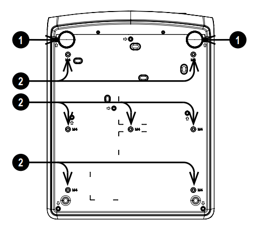
Label Locations
- Location of Hazard Warning Symbol and Laser Aperture Label on the body of the projector.
- Location of Manufacturer’s ID Label and Explanatory Label with Certification Statement and Risk Statement on the body of the projector.
Operation and Configuration
- Software updates should NOT be carried out except by, or with the supervision of, Digital Projection Service personnel.
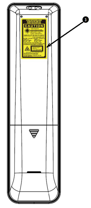
Positioning the screen and projector
- Install the screen, ensuring that it is in the best position for viewing by your audience.
- Set the adjustable feet so that the projector is level and perpendicular to the screen.
- Mount the projector, ensuring that it is at a distance from the screen for the image to fill the screen.
- The drawing shows the positions of the feet for mounting and the fixing holes for ceiling mounting.
- Two adjustable feet Seven M4 holes for ceiling mount.
- The screws should not penetrate more than 8 mm into the body of the projector.
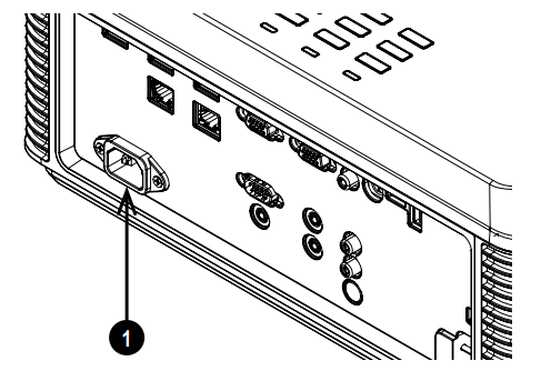
Connecting the Power Supply
- Firmly push the mains connector into the AC In socket U
Switching the Projector On
- On the projector control panel, the POWER button.
- The POWER indicator begins flashing green.
- In approximately 20 seconds, the startup screen appears. The projector is now switched on.
- The first time you use the projector, you can set the D language from the quick menu.
Projector Off
- Press OFF on the remote control or POWER on the control panel, then press again to confirm your choice. The POWER indicator on the control panel will start flashing green, the light source will go out, and the cooling fans will run for a short time.
- The POWER indicator stops flashing green and changes to solid green when the projector enters Standby mode. If you need to switch the projector off completely, wait until the projector enters Standby mode, then disconnect the AC power cable from the projector.
Input Signal
- Connect one or more image sources to the projector.
- Select the input you want to display.
- Press one of the input buttons or the source button on the remote control.
- Use the UP and DOWN navigation buttons to select the input source in the SOURCE menu.
- Press ENTER to confirm your choice.
- Press MENU on the remote control or control panel and navigate to the Source setting in the Settings 1 tab, or press SOURCE on the control panel.
Selecting a Test Pattern
The following test patterns are available: RGB Ramps, Color Bars, Step Bars, Check Board, Grid, Horizontal Lines, Vertical Lines, Diagonal Lines, Horizontal Ramp, Vertical Ramp, White, Red, Green, Blue, Black, None.
To Display a Test Pattern
- Press MENU on the remote or control panel to open the OSD.
- Use the LEFT and RIGHT arrow buttons to access the Settings 1 menu.
- Use the UP, DO W, N, and RETURN buttons to access the Advanced 2 sub menu.
- Highlight Test Pattern and select a test pattern using the LEFT and RIGHT arrow buttons.
Geometry
- Settings such as Keystone and 4 Corners can be set from the Settings 1 menu.
- Keystone requires an external signal inputto enable it to be set.
Picture
Settings such as Display Modes, Brightness, Contrast, Color Manager (Saturation, Gain), and Advanced (Sharpness and Gamma) can be set from the Image menu. This product includes a DICOM simulation feature intended for training and other non-medical diagnosis purposes.
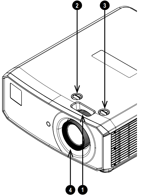
Adjusting the Lens
The lens can be adjusted using the controls on the lens and the controls on the body of the projector:
- Use the horizontal shift control 2 and the vertical shift control 3 on the body of the projector to adjust the position of the image on the screen.
- Use the focus control on the lens to focus the image. See Remote control on page 29 for full details of how to adjust the lens using the remote control.
Control Panel
- AUTO: Optimizes the image sizepositionsi,tion and resolution
- Arrow buttons & ENTER: Navigation buttons are used to highlight menu entries in the OSD.
- SOURCE: Displays and exits the source menu
- POWER: Switches the projector on and off (STANDBY).
- MENU: Displays and exits the OSD.
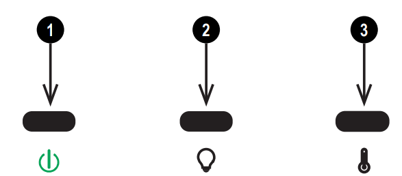
Projector indicators
- Power On = the projector is switched on. Flashing = starting up or cooling down
- Light On = error
- Temp. On = error
Ceiling Mount
When installing a ceiling mount, make sure the weight limit is not exceeded, and the projector is firmly secured. The projector can be operated from any position, as shown in the diagram: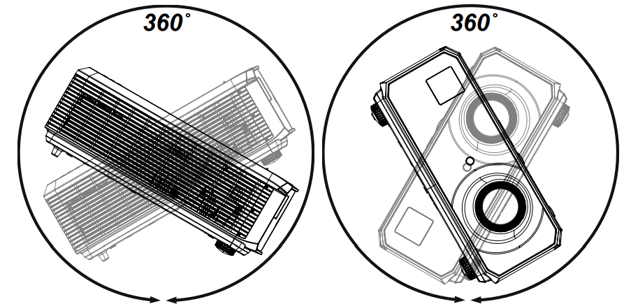
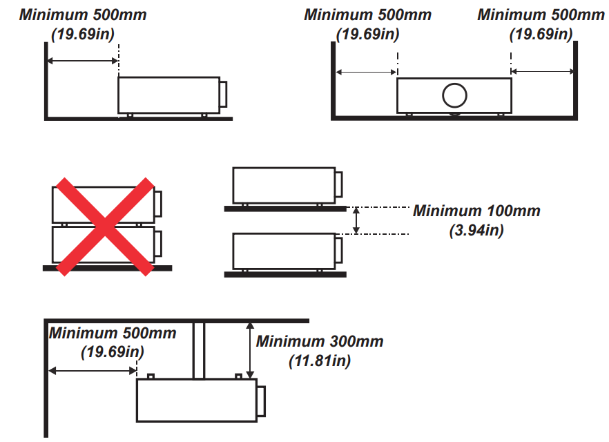
Allow at least 50cm (19.7in) of space between the ventilation outlets and any wall, and 30cm (11.8in) on all other sides.
Make sure the lens cap is removed from the lens before operating the projector. Light energy levels have been known to cause damage to both the lens and projector optics. This damage is not covered by our warranty. Connect the LAN cable only to a computer LAN connection. Other similar connectors may have a dangerously high voltage source. DO NOT insert or remove the signal cable or the power cord to avoid damaging the projector.
Electrical and Physical Specifications
- Mains Voltage 100-240VAC 50/60Hz 5.3A
- Operating Temperature 0°C to 40°C (32°F to 104°F)
- Storage Temperature -20°C to 60°C (-4°F to 140°F)
- Operating Humidity 10% to 85% non-condensing
- Storage Humidity 5% to 95% non-condensing
- Dimensions L:445.6mm (17.54in) X W: 360mm (14.17in) X H: 163.5mm (6.43in)
- Weight 11Kg (24.2lb) including lens
- Power Consumption at 100VAC: 500W typical (normal mode) at 240VAC: 480W typical (normal mode)
- Standby Power <2W (With LAN enabled), <0.5W (Without LAN enabled)
- Thermal Dissipation at 100VAC: 1706BTU/Hour, typical at 240VAC: 1638BTU/Hour typical.
- Fan Noise 36dBA typical, 38dBA max (Normal mode)
Laser Parameters
- Wavelength 450-460nm (Blue)
- Mode of operation: Pulsed, due to frame rate
- Pulse duration 1.34ms
- Pulse repetition rate 120Hz
- Maximum pulse energy 0.698mJ
- Total internal power >100W
- Apparent source size >10mm, at lens stop
- Divergence >100 mili Radian
Compliance with International Standards
The Federal Communications Commission does not allow any modifications or changes to the unit EXCEPT those specified by Digital Projection in this manual. Failure to comply with this government regulation could void your right to operate this equipment.
This equipment generates, uses, and can radiate radio frequency energy and, if not installed and used in accordance with the instruction manual, may cause harmful interference to radio communications. Operation of this equipment in a residential area may cause harmful interference, in which case the user will be responsible for correcting any interference.
Contact Information
Europe
DigitalProjection Limited, Ted Greenside Way, Middleton, Manchester, M24 1XX, UK Registered in England No. 2207264
- Tel: (+44) 161 947 3300
- Fax: (+44) 161 684 7674
- Website: www.digitalprojection.co.uk
North America
DigitalProjection Inc. 55 Chastain Road, Suite 115, Kennesaw, GA 30144, USA
- Tel: (+1) 770 420 1350
- Fax: (+1) 770 420 1360
- Website: www.digitalprojection.com
Additional Documentation
Please use the QR code (also located on the projector) to access the latest EVision projector user guides and other documentation via the Digital Projection website. Or visit the product’s specification page on the Digital Projection website to download the latest user guide and other documentation.