
Seeed Studio SenseCAP Indicator 4-inch Touch Screen
Introduction
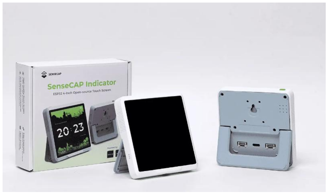
The Seeed Studio SenseCAP Indicator 4-inch Touch Screen is a powerful 4-inch touch display driven by ESP32 and RP2040 dual-MCU, supporting Wi-Fi, BLE, and LoRa communication. This board comes with Type-C and Grove interfaces, supports ADC and IIC protocols, and can easily connect to other peripherals with its rich GPIOs. The Seeed Studio SenseCAP Indicator 4-inch Touch Screen is a fully open-source IoT development platform for developers, with a one-stop ODM Fusion service available for quick customization and scale-up. For developers looking to expand their IoT projects with advanced presence detection, you can also check the Seeed Studio MR24HPC1 Human Static Presence Module User Guide.
Features
The Seeed Studio SenseCAP Indicator 4-inch Touch Screen offers advanced capabilities for IoT projects and real-time monitoring.
- Dual MCUs and Rich GPIOs: Equipped with powerful ESP32S3 and RP2040 dual MCUs and over 400 Grove-compatible GPIOs for flexible expansion options.
- Real-time Air Quality Monitoring: Built-in tVOC and CO2 sensors, and an external GroveAHT20 temperature and humidity sensor for more precise readings.
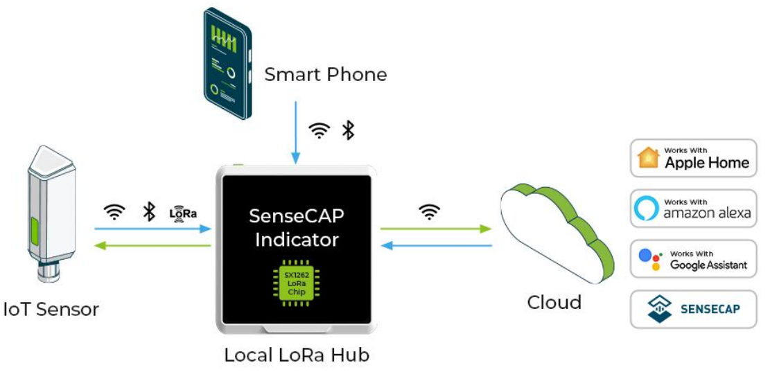
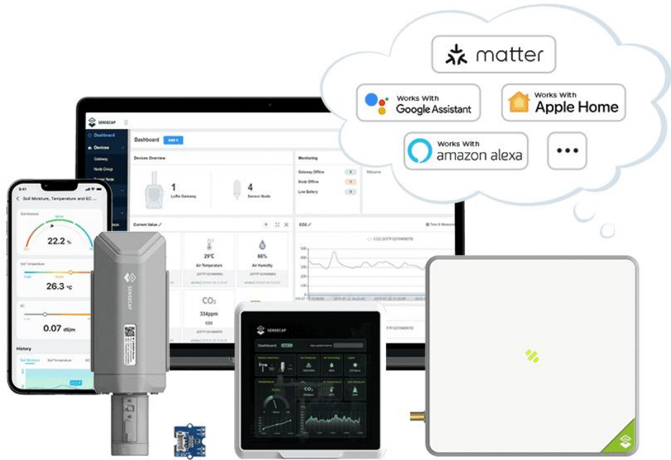
- Local LoRa Hub for IoT Connectivity: Integrated Semtech SX1262 LoRa chip (optional) for connecting LoRa devices to popular IoT platforms such as Matter via Wi-Fi, without the need for additional compatible devices.
- Fully Open Source Platform: Leverage the extensive ESP32 and Raspberry Pi open source ecosystem for infinite application possibilities.
- Fusion ODM Service Available: Seeed Studio also provides a one-stop ODM service for quick customization and scale-up to meet various needs.
Indicator Instructions
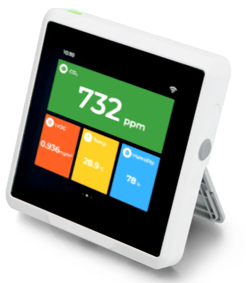
SenseCAP Indicator native firmware enables you to use it as a desktop air quality detector, or you could customize one of your own styles. There are built-in TVOCs and CO2 sensors, and a GroveTH sensor is provided to connect externally to reduce heat interference to get more accurate temperature and humidity results.
The embedded SX1262 LoRa module enables you to build the LoRa application and connect your local LoRa sensors to the Cloud via Wi-Fi. For example, you could build a LoRa hub device to connect your LoRa sensors to your smart home ecosystem to implement Matter over Wi-Fi. In this way, the LoRa devices could be connected to the Matter ecosystem via Wi-Fi, without the need to buy a new Matter-compatible device.
Description
The software of the SenseCAP Indicator is open source. Developers could create various IoT applications, such as:
- Air Quality Monitor
- Weather Station Display
- Sensor Data Dashboard
- Smart Home Assistant
- Mini Sensor Hub
- Stock Price Indicator
- Digital Album
- SOP Reminder
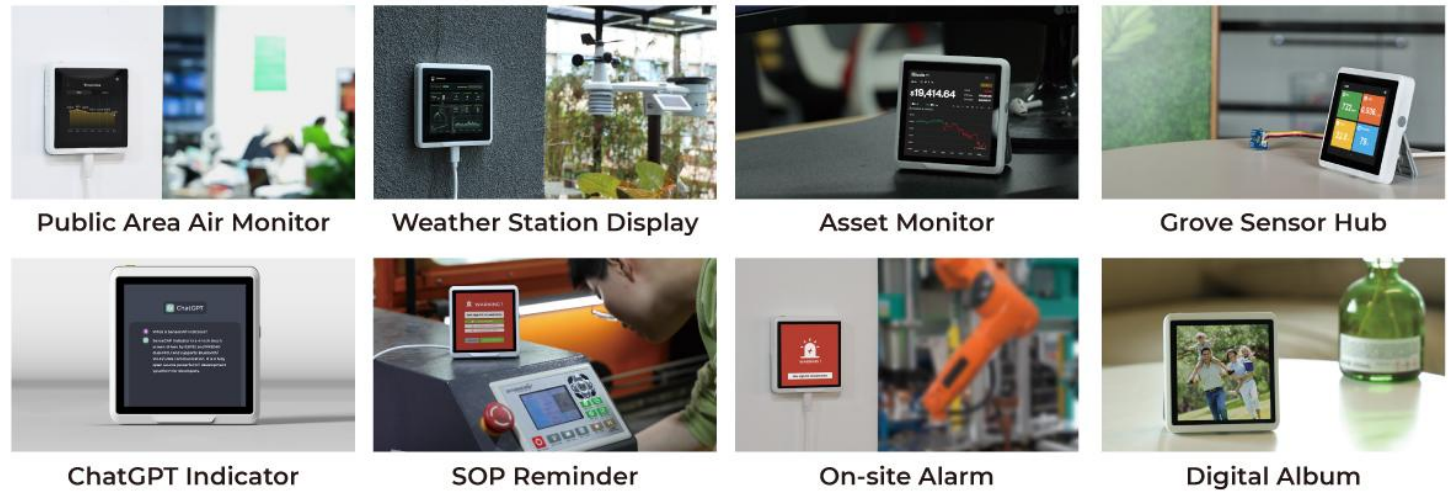
It can also be used to develop various exciting applications integrating with third-party platforms, such as AWS / ChatGPT / Matter / NodeRED / IoTex.
SenseCAP Indicator is an interactive display and control terminal for various IoT applications. It
provides developers with a powerful and interface-rich development platform, powered by ESP32-S3 and RP2040 dual-MCU. Don’t wait any longer, start your wonderful development journey with SenseCAP Indicator now!
Hardware Version
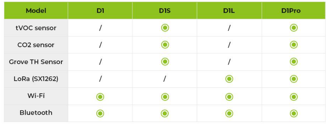
The SenseCAP Indicator series offers four different versions: D1, D1S, D1L, and D1Pro. Each version is designed to meet different application needs without any extra cost from unnecessary hardware. Here are the differences between the versions:
Specification
| Screen | 3.95 Inch, Capacitive RGB Touch Screen | |
| Screen Resolution | 480 x 480 pixels | |
| Power Supply | 5V DC, 1A | |
| Operation Temperature | -10℃~50℃ | |
| Battery | N/A | |
| Processor | ESP32-S3: Xtensa® dual-core 32-bit LX7 microprocessor, up to 240 MHz RP2040: Dual ARM Cortex-M0+ up to 133MHz | |
| Flash | ESP32S3: 8MB/RP2040: 2MB | |
| External Storage | Support up to 32GB Micro SD Card (not included) | |
| Wi-Fi | 802.11b/g/n, 2.4GHz | |
| Bluetooth | Bluetooth 5.0 LE | |
| LoRa(SX1262) | LoRaWAN/(G)FSK, 21dBm Max Transmitted Power Sensitivity/-136dBm@SF12 BW=125KHz RX Sensitivity, Up to 5km (depending on gateway antenna and environments) | |
| Sensors(Optional) | CO2 (SCD41) | Range: 0-40000ppm Accuracy: 400ppm – 5000pp4m ±(50ppm+5% of reading) |
| TVOC (SGP40) | Range: 1-500 VOC Index Points | |
| Grove Temperature and Humidity Sensor (AHT20) | Range: -40 ~ + 85 ℃/± 0.3 ℃; 0 ~ 100% RH/± 2% RH (25 ℃) | |
| Buzzer | MLT-8530, Resonant Frequency:2700Hz | |
Part List
| Products | Quantity |
| SenseCAP Indicator | *1 |
| Grove TH Sensor(For D1Pro and D1S) | *1 |
| Type-C Cable | *1 |
ODM Service
With over 10 years of ODM & OEM experience, our engineers and product experts are proficient in delivering customization services for popular open-source hardware platforms, such as Raspberry Pi, NVIDIA Jetson, Beagleboard, ESP32, and more. We are committed to assisting you at any moment and shortening your path from idea to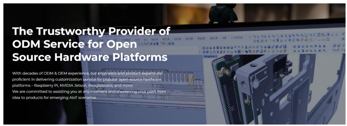 Overview
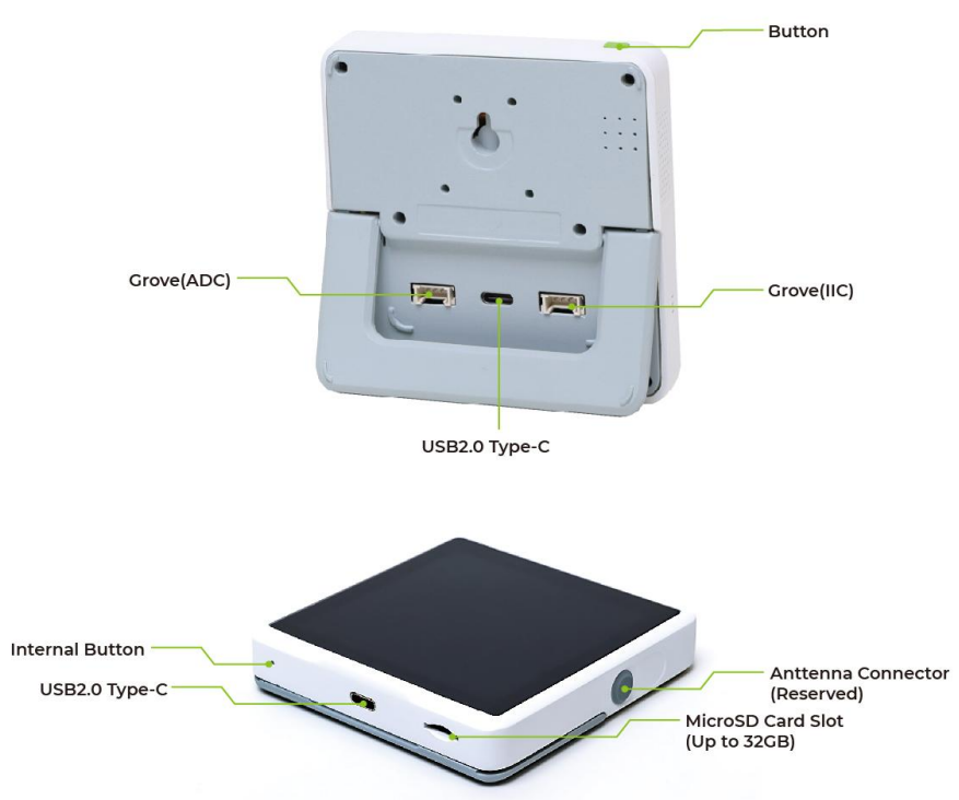
Button Function
Short press: Turn off /wake up the screen. Long press for 3s: Switch on/switch off the deviceLong press for 10s: Factory reset
Grove Interfaces
There are two Grove interfaces for connecting Grove modules, providing more possibilities for developers. Grove is a modular, standardized connector prototyping system and a strong open source hardware ecosystem. Click Grove – Seeed Studio to learn more)Grove – Seeed Studio
SX1262 LoRa Chip
The embedded SX1262 LoRa module enables you to build the LoRa application and connect your local LoRa sensors to the Cloud via Wi-Fi. For example, you could build a LoRa hub device to connect your LoRa sensors to your smart home ecosystem to implement Matter over Wi-Fi. In this way, the LoRa devices could be connected to the Matter ecosystem via Wi-Fi, without the need to buy a new Matter-compatible device.

Native Firmware
SenseCAP Indicator native firmware enables you to use it as a desktop air quality detector, with just a few simple steps to enjoy
Wi-Fi Configuration
Plug the 5V power adaptor into the USB Type-C power connector, and he device will power on automatically, then the display will show the WiFi settings page.
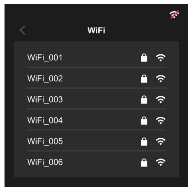
Select the WiFi you need, input the password, and connect.
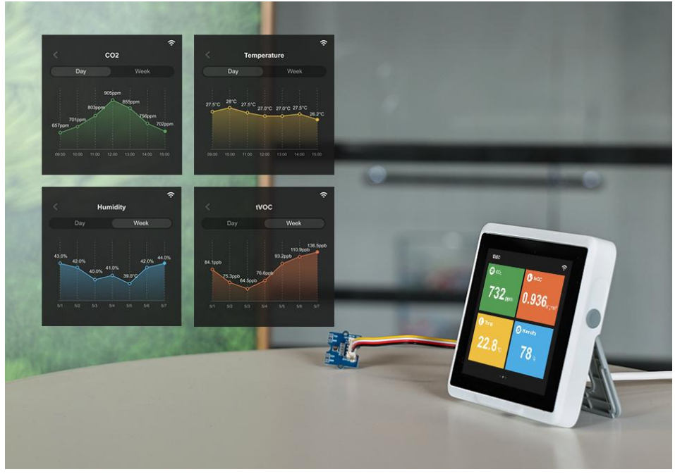
Data Viewing
- Home page
Including the time, date, and location info.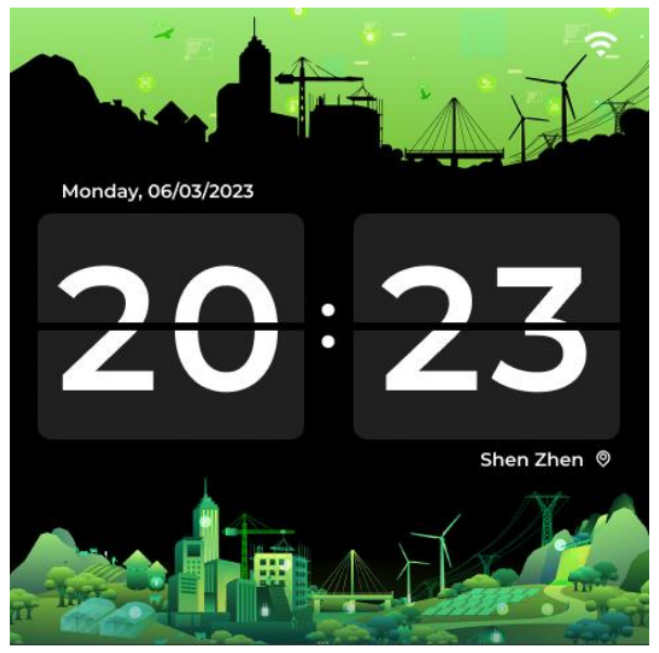
Sensor Data
Built-in TVOC and CO2 sensors, and an external Grove AHT20 TH sensor for more precise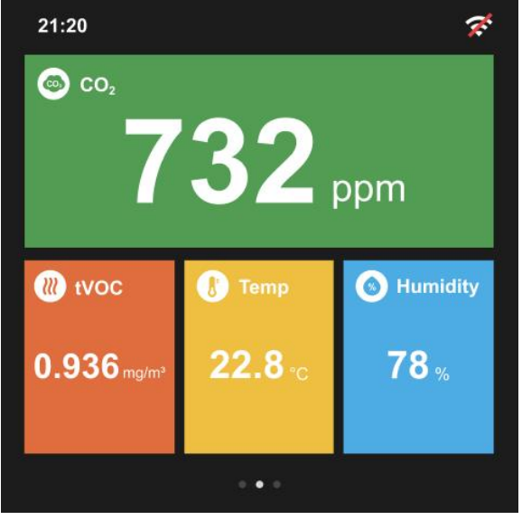
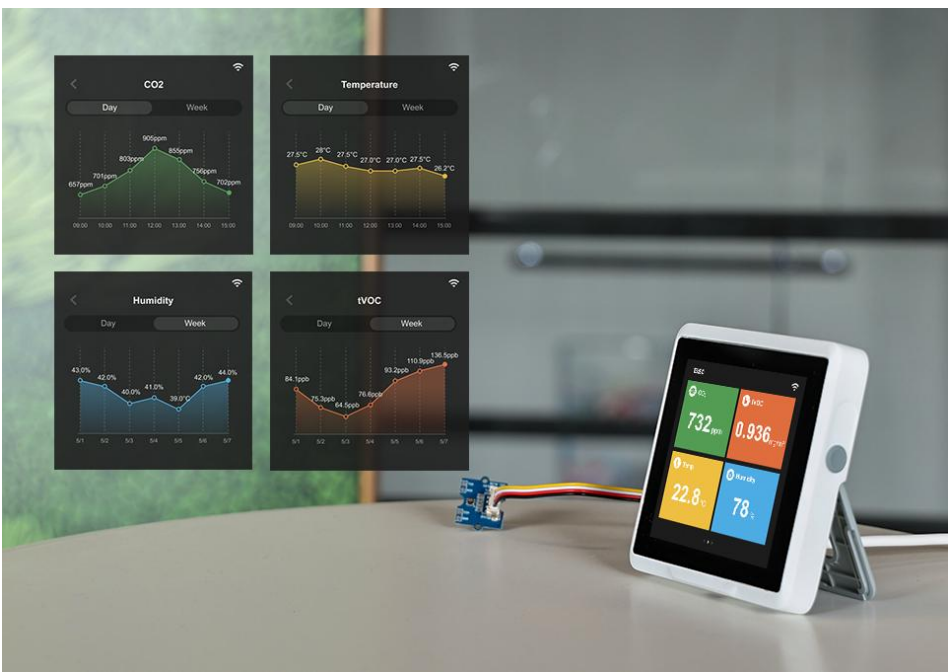
Click the specified sensor to enter the detailed information page, and you can choose to display the value for 24h or a week.
Setting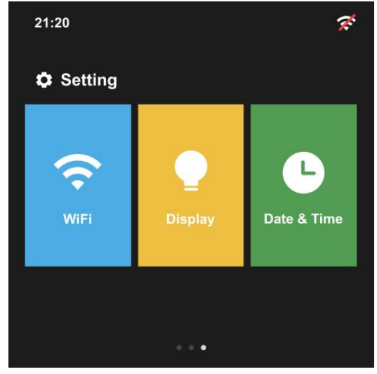
Display Setting
Brightness: Adjust screen brightness. Sleep Mode: Turn off the screen according to the interval you set

Date & Time Setting
Time Format: You can set 24H or 12H format. Time Auto Update/Zone Auto Update: When the device is connected to WiFi, it will automatically obtain the corresponding time zone and date.
Manual setting: If the time obtained through the time zone cannot
automatically identify the winter time or device is offline, then you can manually set the time zone
Development Tutorial
ESP32 Firmware Flashing\ Flash by Flash Download Tools (For Windows only)
- Step 1: Connect the device to your PC with the provided USB-C cable.
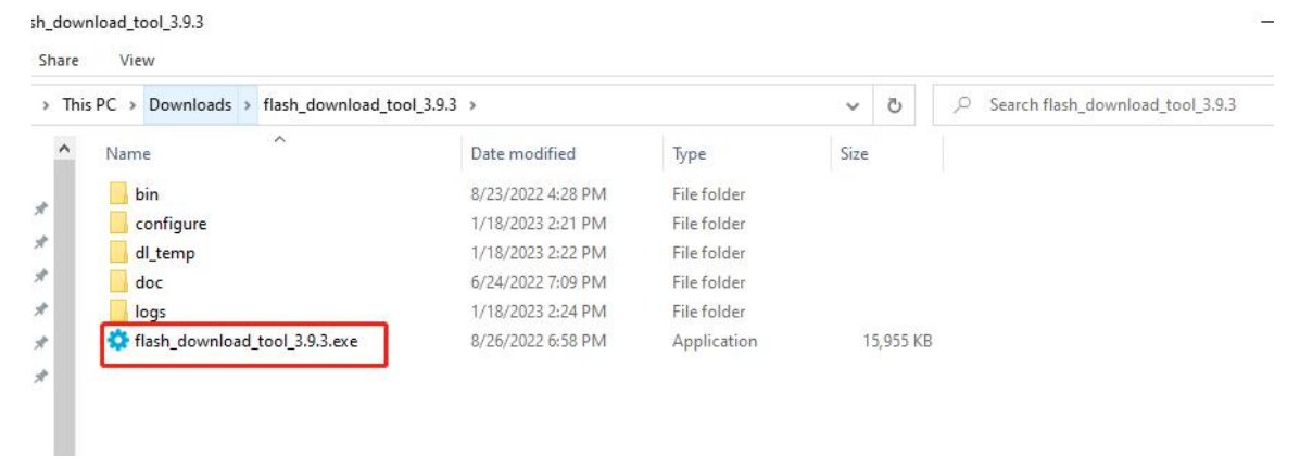
- Step 2:Install the Flash Download Tools
Flash Download Tools for Windows
- Step 3: User interface settings
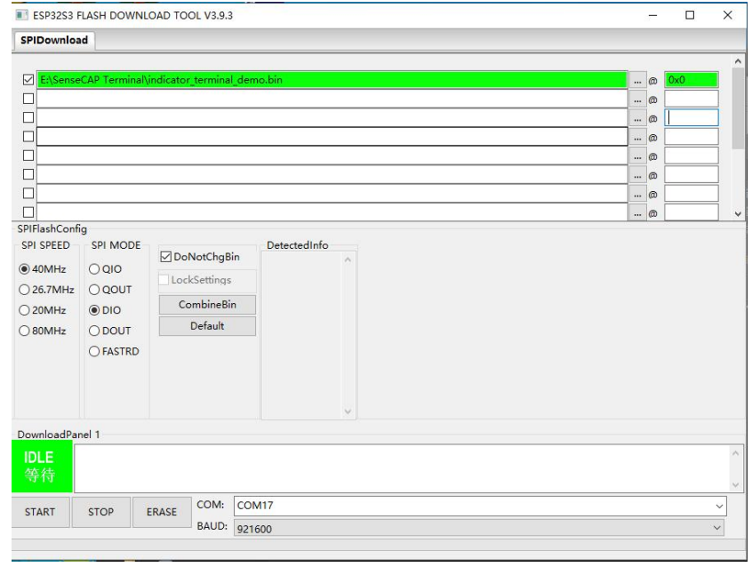
Double-click the .exe file to enter the main interface of the tool. Chip Type: ESP32-S3 WorkMode: Develop\ LoadMode: UART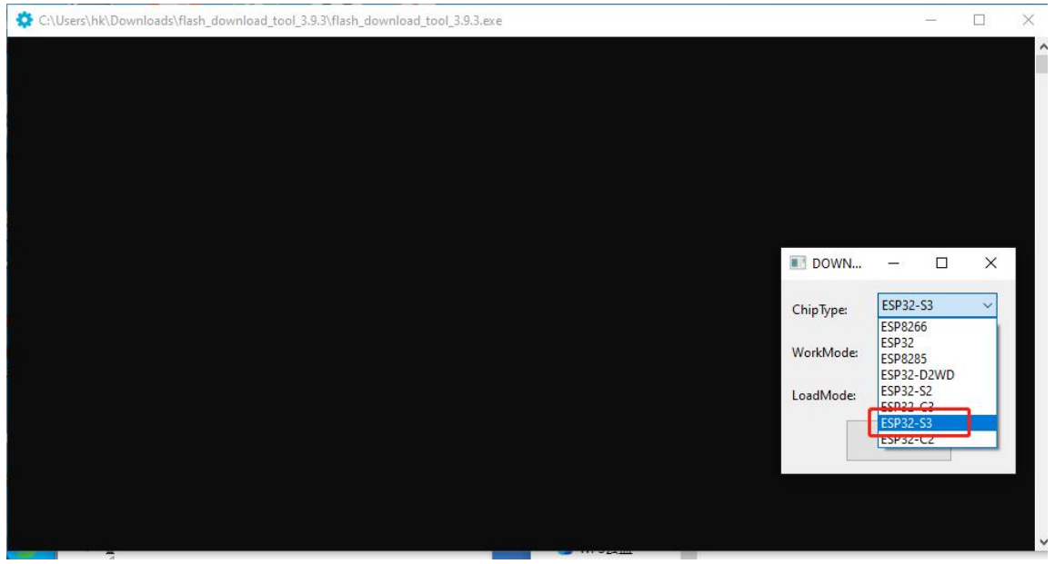
- Step 4: SPI Download Tab Configure
Click “…” and select the .bin file in the firmware file to configure the loading path. There should be 3 .bin files in the firmware, they correspond to 3 different downloading addresses: bootloader.bin – 0x0
partition-table.bin – 0x8000 terminal.bin – 0x10000

- Step 5: SPI Flash Configure
SPI SPEED: 40MHz SPI MODE: DIO
- Step 6: Download Panel Configure
COM: Check the ports on your Device Manager, the USB-SERIAL is the correct one. Baud: 921600(recommended value)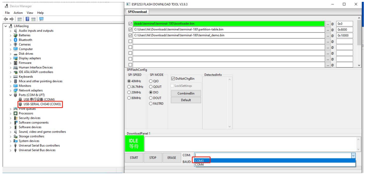
Then click “START” to start the download.
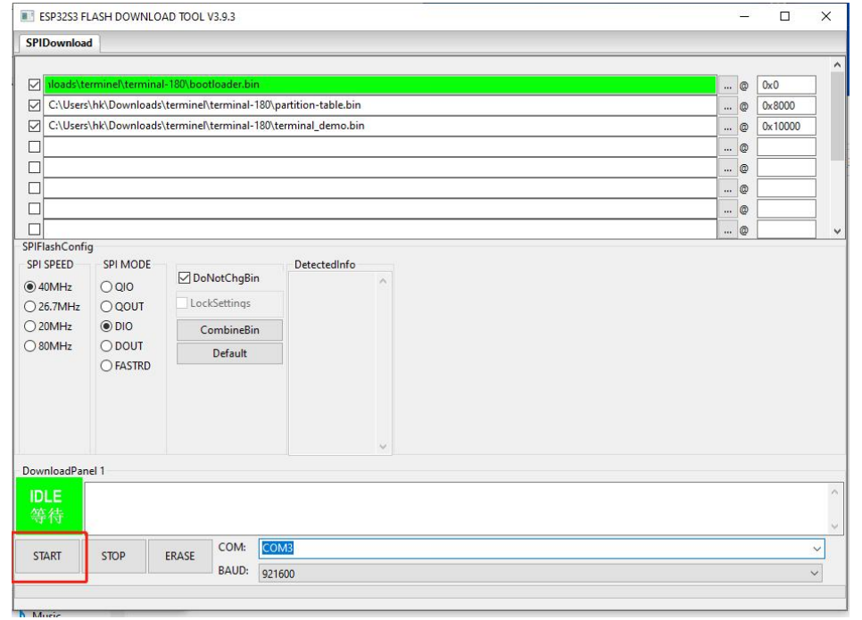
When it shows “FINISH”, the flash has been completed.
There is “indicator_terminal_demo.bin” firmwareall-in-oneee) In tSDKyouDK, you can flash it to ESP32.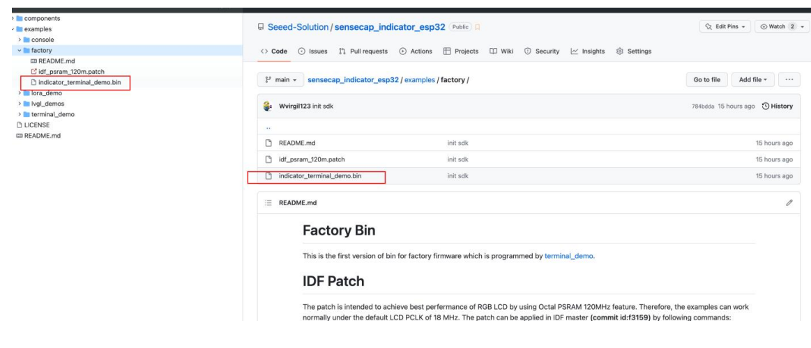
Flash by IDF
For Linux and macOS: Standard Toolchain Setup for Linux and macOS. For Windows: Standard Setup of Toolchain for Windows. There is an “indicator_terminal_demo.bin” firmware (all-in-one) in the SDK.DK that can flash it by IDF.
Cd/examples/factory/ esptool.py write_flash 0x0 indicator_terminal_demo.bin. Also, you can build, flash, and monitor the project. cd /examples/terminal_demo/
RP2040 Firmware Flashing
- Step 1: Connect the device to your PC
Long-press this internal button, then connect the device to your PC by the provided USB Type-C cable, and release the button once connected.
Step 2: Firmware Flash
After the connection is successful, your PC will show a disk.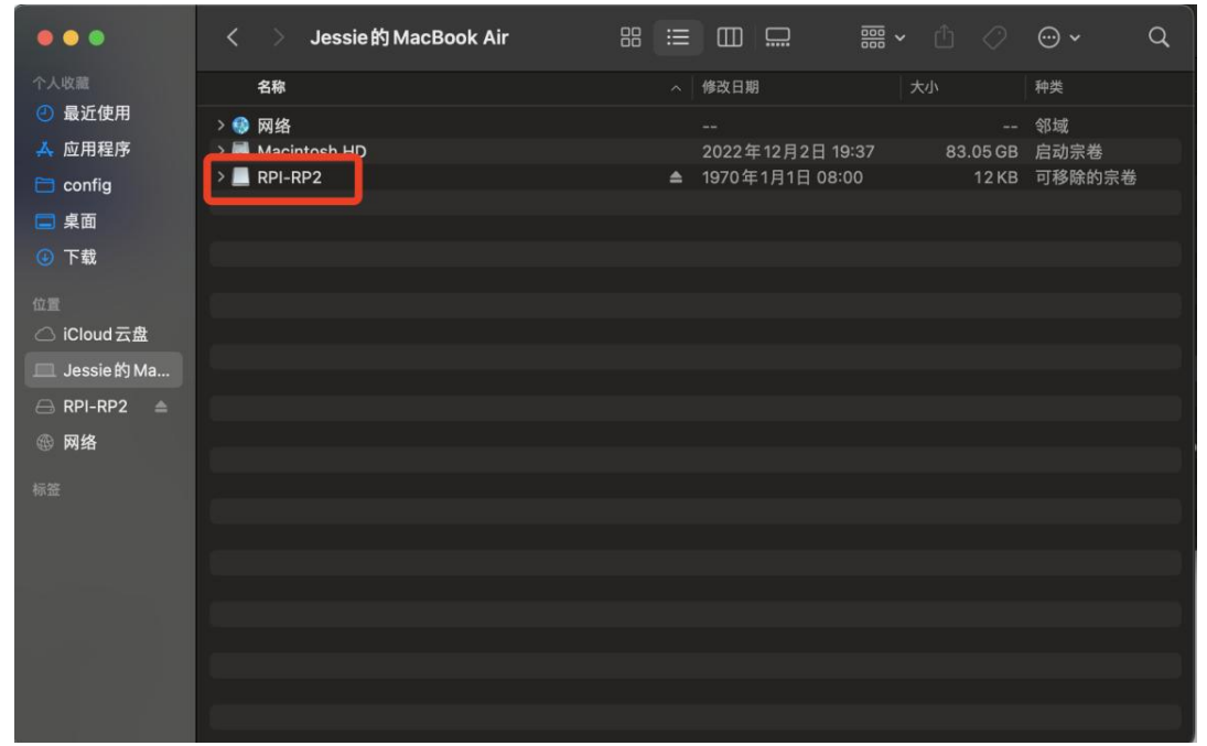
Copy the .uf2 file in the firmware package to the disk, then the disk will log out. The upgrade will run automatically
Flash by Arduino IDE
- Step 1: Install Arduino IDE
Arduino IDE
- Step 2: Add the Raspberry Pi Pico Board
Open your Arduino IDE, click on Arduino > Settings, and copy the URL below to Additional Boards Manager URLs: https://github.com/earlephilhower/arduino-pico/releases/download/global/package_rp2040_index..json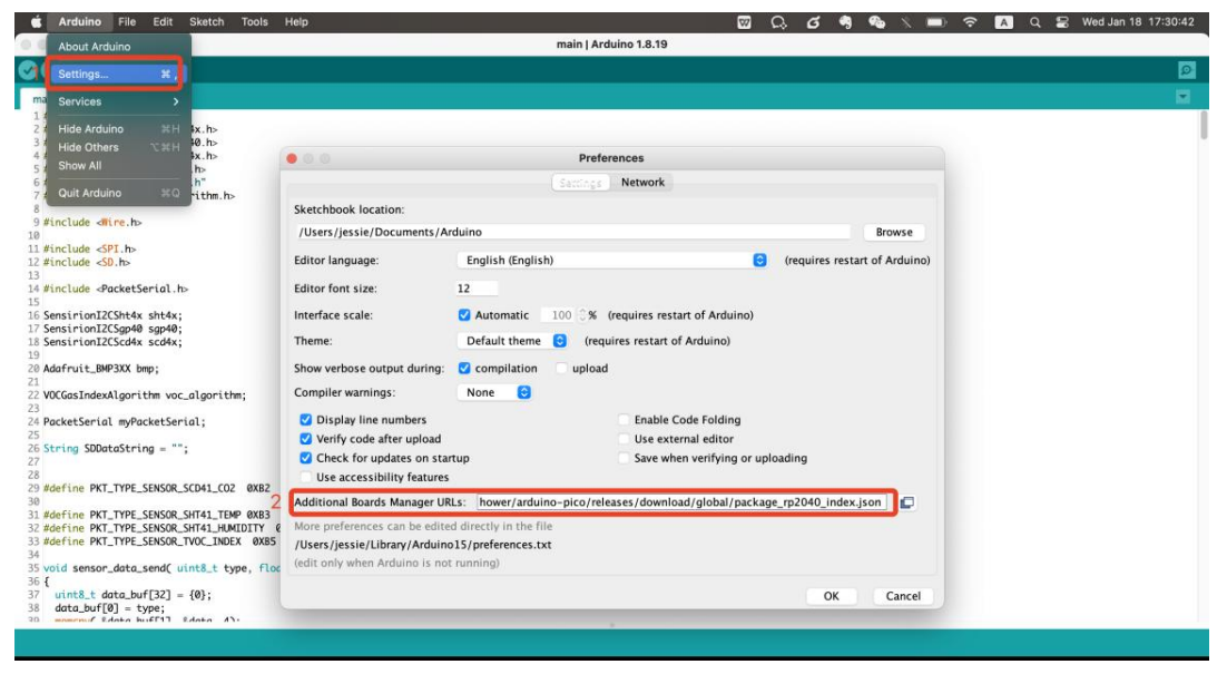
Click on Tools > Board > Board Manager.
Search for and install “Raspberry Pi Pico/RP2040” in the Boards Manager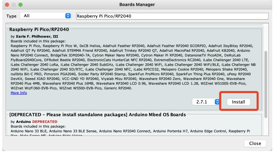
- Step 3: Add Libraries
Download these libraries we need:
Navigate to Sketch -> Include Library -> Add .ZIP Library, then select the libraries you downloaded.
- Step 4: Connect the device to your PC with the provided USB Type-C cable.
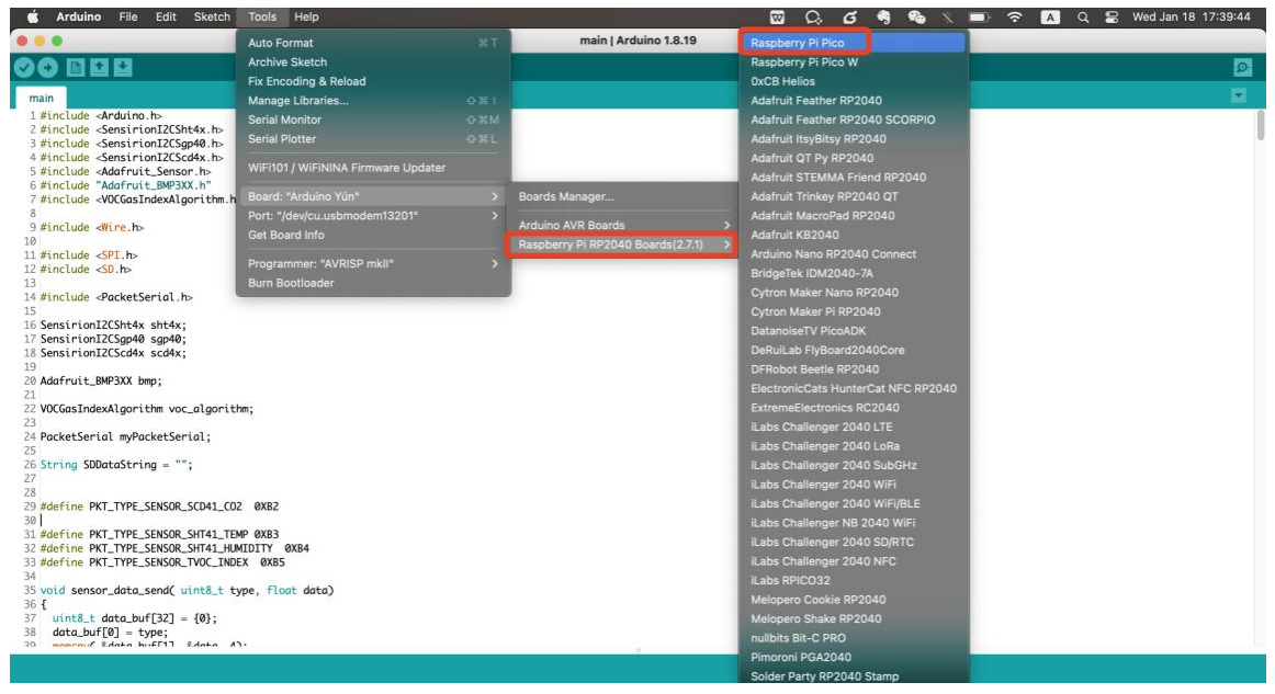
- Step 5: Select the board Tools > Board > Raspberry Pi PR2040 Boards > Raspberry Pi Pico
Port: Select the “usbmodem” one
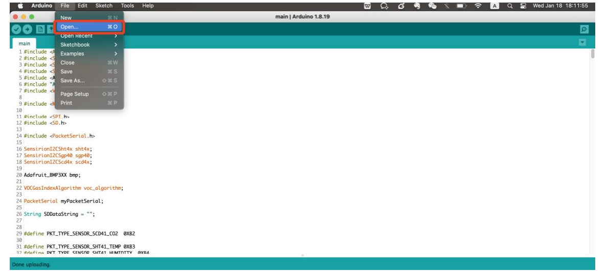
- Step 6: Open the example code file

File > Open, then select the example code file (.ino file). We provide an example code file; you can modify the code according to your needs.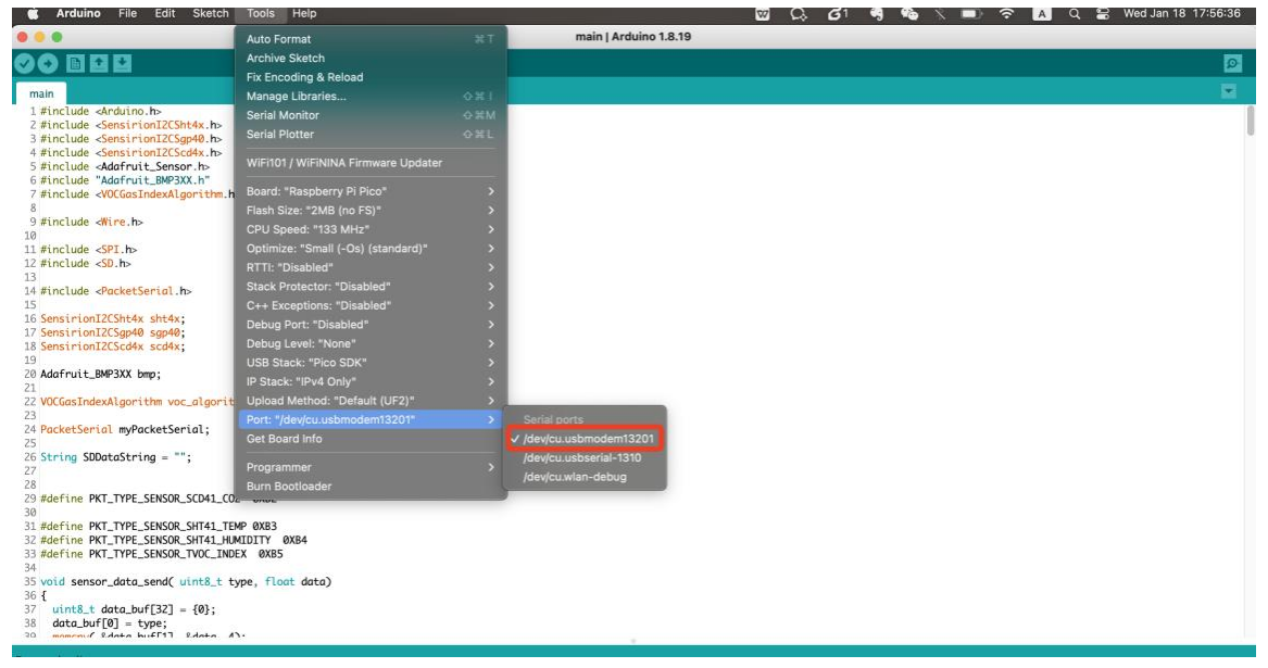
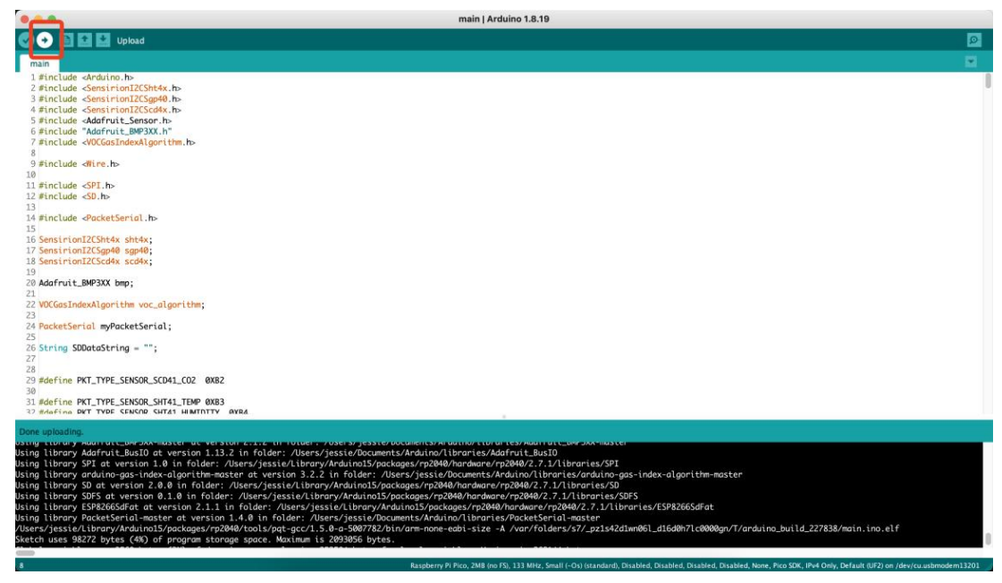
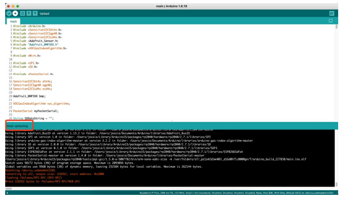
- Step 7: Verify and upload the file.
FCC Regulatory Conformance
This device complies with Part 15 of the FCC Rules. Operation is subject to the following two conditions:
- This device may not cause harmful interference
- This device must accept any interference received, including interference that may cause undesired operation.
RF Exposure
This equipment complies with FCC radiation exposure limits set forth for an uncontrollenvironmentntt. This equipment should be installed and operated with h minimum distance of 20cmbetween the radiator and your body. This transmitter must not be co-located or operating in conjunction with any other antenna or transmitter.
Customer Support
- Website: www.seeedstudio.com
- Ph: +86-0755-86095676
2008-2025 Seeed Technology Co., Ltd. All rights reserved.
FAQs
Q: What is the SenseCAP Indicator 4-inch Touch Screen?
The SenseCAP Indicator 4-inch Touch Screen is a small, interactive display made for industrial and Internet of Things applications that monitor, control, and visualise data. It seamlessly integrates with other Q: microcontrollers and SenseCAP devices and has a capacitive touch interface for easy user interaction.
Can I display real-time IoT data on the screen?
Indeed. The purpose of the SenseCAP Indicator is to display notifications, system metrics, or sensor data. To display real-time data, use microcontroller code or SenseCAP APIs.
Q: What is the power requirement?
Usually, a 4-inch screen needs 5V DC. Although power consumption varies with activity and brightness, it is typically low, making it appropriate for embedded and portable applications.
Q: Can the screen display notifications or alerts?
Indeed. To show notifications, messages, or colour changes on the touch screen, you can set thresholds or triggers in your software. This is helpful for keeping an eye on system or environmental parameters.
Q: Is it compatible with third-party IoT platforms?
Yes, provided that the platform can transmit data through the USB, UART, and SPI interfaces that are supported. For complete compatibility, you might have to create or modify drivers or scripts.
Q: Can multiple screens be used simultaneously?
Indeed. A multi-display monitoring system can be created by connecting multiple SenseCAP Indicators to various devices or gateways. Make sure every screen has its own data input and a reliable power source.
Q: Where can I find software examples and guides?
Seeed Studio’s wiki and GitHub provide official examples, dashboards, and code snippets. These consist of touch controls, API integration manuals, and real-time sensor dashboards.