
 Seeed Studio Wio-E5 TM32WLE5JC Wireless Module
Features
The Seeed Studio Wio-E5 TM32WLE5JC Wireless Module offers a range of advanced features designed for low-power IoT applications.
- Ultra-low power consumption and high performance
- Easy testing and rapid prototyping
- CAN FD communication
- RS485 Interface
- Global LoRaWAN and Long Range frequency plan supported
- Long-distance transmission range to 10km(ideal value in an open area)
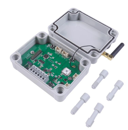
Overview
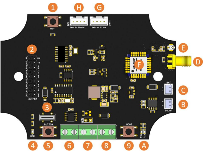
- Reset button
- 2×9 Header
- Type-C USB
- User LED
- User Button
- 485 Interface
- CAN Interface
- Power Input (5-28V)
- Boot button
- A. CAN send/recv indicators
- B. Solar input
- C. Lipo battery input
- D/E. Antenna
- F. Wio E5 Module G/H. Grove connector
Application
The Seeed Studio Wio-E5 TM32WLE5JC Wireless Module is commonly used in long-range IoT sensor networks, especially where stable LoRa communication is required.
- A common Lora usage scenario is building a long-range sensor network. A large
number of sensors in the industry are transmitted through CAN Bus. For instance, the Seeed Studio MR60BHA1 Heartbeat Detection Sensor can be integrated into such networks to monitor vital data and transmit it via LoRaWAN. With the Wio-E5 CANBus Dev board, you can use the on-board CAN Bus function to read the sensors, and send the data through Long Range - Since the circuit board can receive 5-28V input, the user can connect the circuit board to the OBD interface, get the data of the car, and send it out through Long Range.
Application
Factory AT Firmware
- Wio-E5 series has a built-in AT command firmware, which supports LoRaWAN Class A/B/Cprotocol and a wide frequency plan: EU868/US915/AU915/AS923/KR920/IN865. With this ATcommand firmware, developers can easily and quickly build their prototype or application. The AT command firmware contains a bootloader for DFU and the AT application.
- The “PB13/SPI_SCK/BOOT” pin is used to control Wio-E5 to stay in the bootloader or jump to the ATAT application. When PB13 is HIGH, the module will jump to AT application after reset with a default baud rate of 9600. When PB13 is LOW (press the “Boot” button on Wio-E5 Dev Board or Wio-E5 mini), the module will stay in the bootloader, and keep transmitting “C” character every 1S at baud rate 115200.
Clock Configuration
HSE
- 32MHz TCXO
- TCXO power supply: PB0-VDD_TCXO
LSE
- 32.768KHz crystal oscillator
3. RF Switch
- Wio-E5 module ONLY transmits through RFO_HP.
- Receive: PA4=1, PA5=0
- Transmit(high output power, SMPS mode): PA4=0, PA5=1
Getting Started
- Quick Start of AT Commands
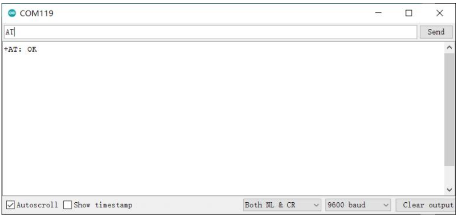
Preparation
- Step 1
Connect the WiO-E5 Development Board to the PC via a Type-C cable
- Step 2
Open a serial tool(eg, Arduino Serial Monitor), select the right COM port, set the baud rate to 960,0, and select Both NL & CR
- Step 3
Try to send “AT” and you will see the response.
Basic AT Commands
The following AT commands are commonly used with the Seeed Studio Wio-E5 TM32WLE5JC Wireless Module for configuring LoRaWAN connectivity and device settings:
- AT+ID // Read all, DevAddr(ABP), DevEui(OTAA), AppEui(OTAA)
- AT+ID=DevAddr // Read DevAddr
- AT+ID=DevEui // Read DevEui
- AT+ID=AppEui // Read AppEui
- AT+ID=DevAddr,”devaddr” // Set new DevAddr
- AT+ID=DevEui,”deveui” // Set new DevEui
- AT+ID=AppEui,”appeui” // Set new AppEui
- AT+KEY=APPKE 16-bytetes length key” // Change application session key
- AT+DR=band // Change the Band Plans
- AT+DR=SCHEME // Check current band
- AT+CH=NUM, 0-7 // Enable channel 0~7
- AT+MODE=”mode” // Select work mode: LWOTAA, LWABP or TEST
- AT+JOIN // Send JOIN request
- AT+MSG=”Data to send” // Use to send d string format frame, which does not need to be confirmed by the server
- AT+CMSG=”Data to send” // Use to send string format frame, which must be confirmed the server
- AT+MSGHEX=”xx xx xx xx” // Use to send nd hex format frame, which does not need to be confirmed by the server
- AT+CMSGHEX=”xx xx xx xx” // Use to send a hex format frame, which must be confirmed by the server
Connect and send Data to TTN
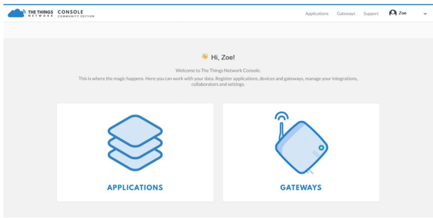
- Step 1
Load the o TTN website: https://www.thethingsnetwork.org and create your account, then access “Console” and first click on “APPLICATIONS.
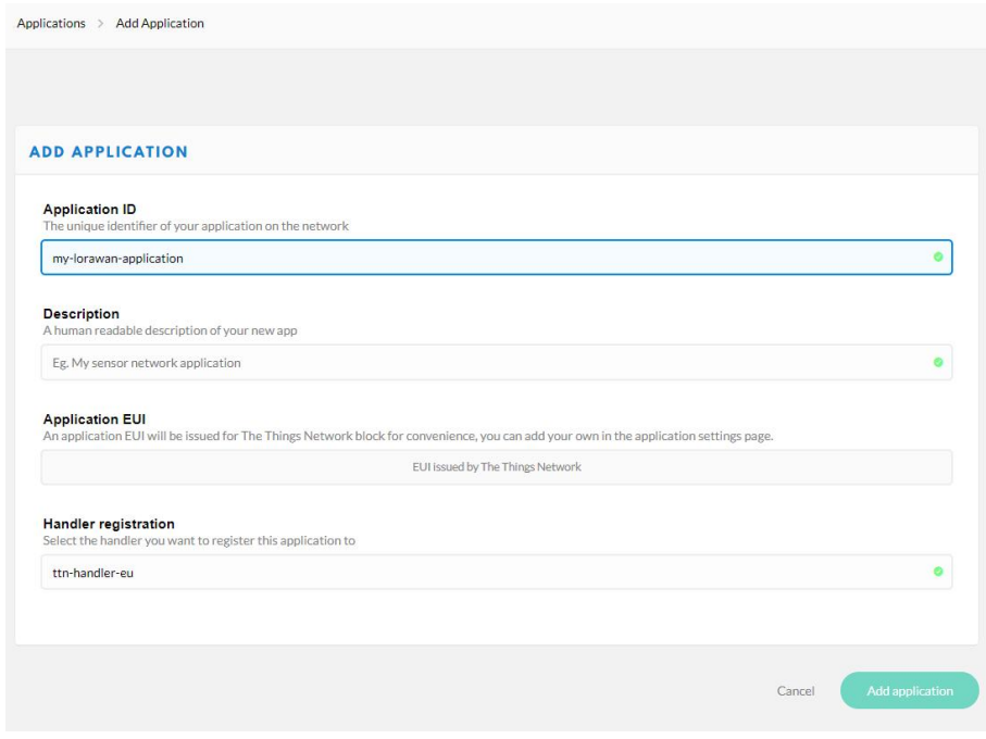
- Step 2
Add an Application
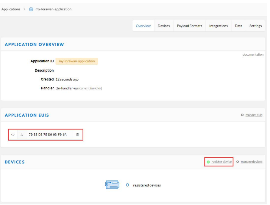
- Step 3
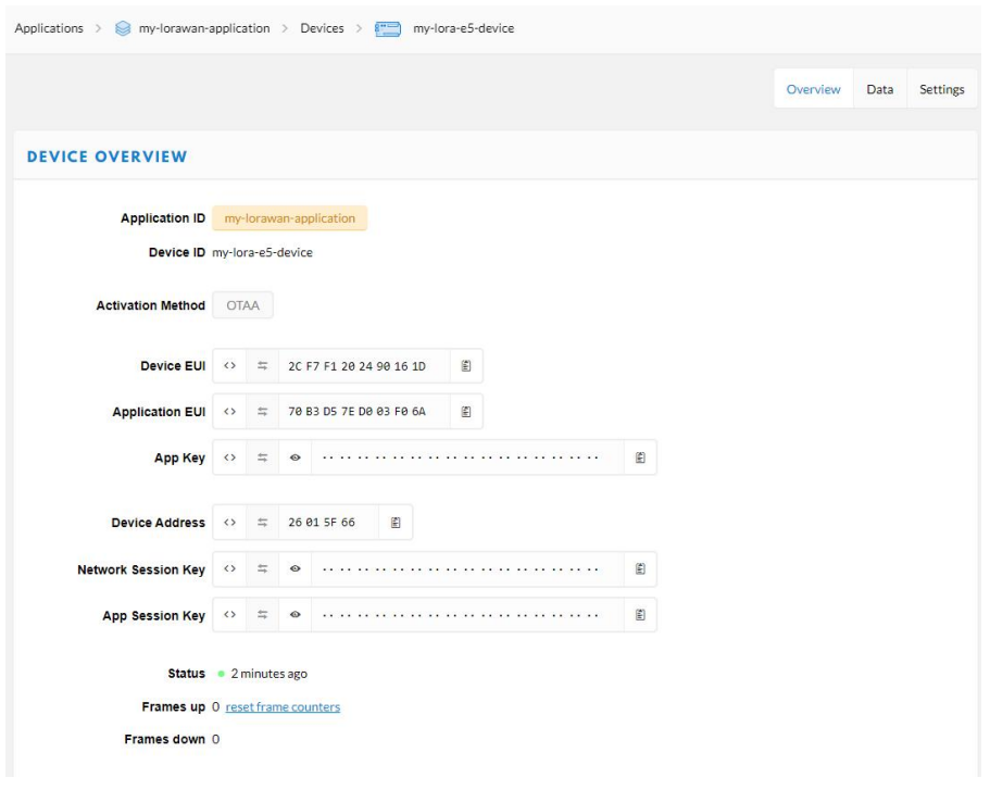
Copy the APPLICATION EUIS and click the “register device” button to add your device to TTN.
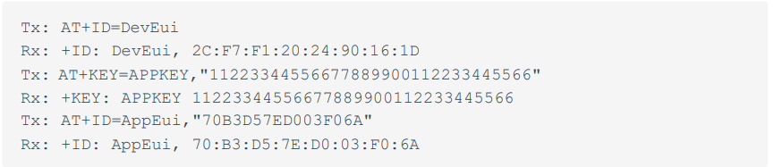
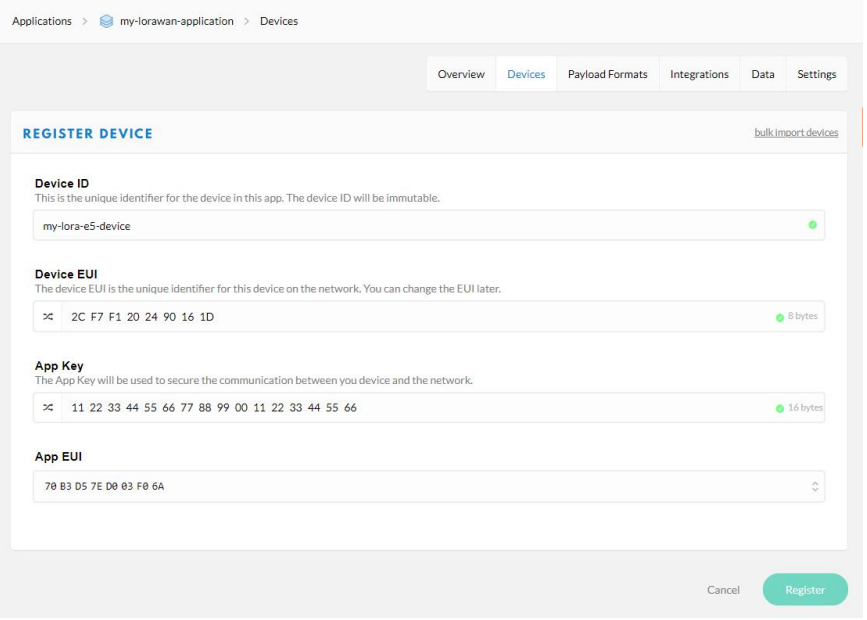
- Step 4
Send AT command AT+ID=DevEu i to get your Device EUl, send AT command AT+KEY=APPKEY, 11223344556677889900112233445566″ to set the App Key, and send AT command AT+ID=AppEui, “APPLICATION EUIS youcopiedy just now” to set the App EUl. Finally, fill in all these EUls and the Key to the page to register your device.
- Step 5
Register your LoRaWAN Gateway on TTN Console. Please refer to instructions shown in The Things Indoor Gateway wiki page: The Things Indoor Gateway Get Started with SenseCA.P
- Step 6
Type the following ACommandnd to connect to TTN
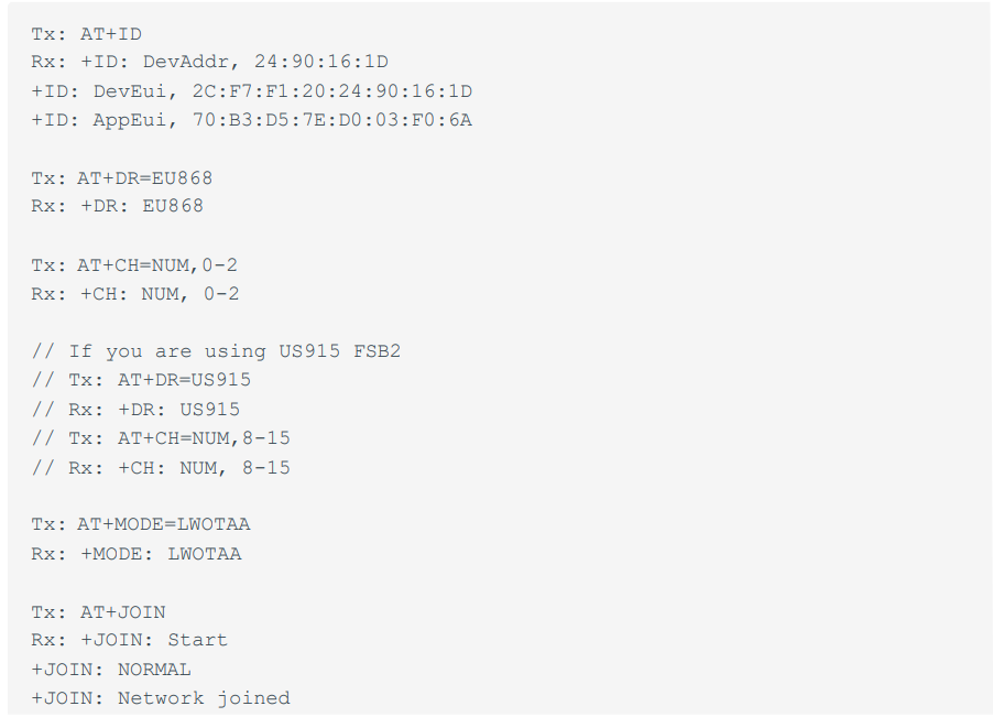
If you see +JOIN: Network joined in your serial console, congratulations, your device has already connected to TTN! You can also check your device status at the “overview” page.
- Step 7
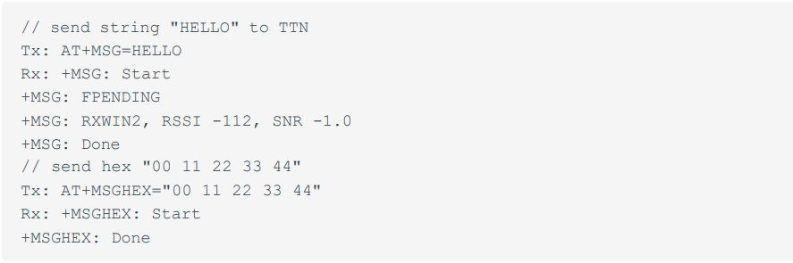
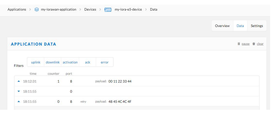
Type the following AT Command to send data to TTN.
- Step 8
For more information about AT Commands, please refer to the Wio-E5 AT Command Specification.
Develop with STM32Cube MCU Package
The Seeed Studio Wio-E5 TM32WLE5JC Wireless Module can be developed easily using the STM32Cube MCU Package for the STM32WL series.
This section is for the Wio-E5 Mini or Wio-E5 Dev Board, aiming at creating a LoRaWAN End Node with the STM32Cube MCU Package for the STM32WL series(SDK), to join and send data to the LoRaWAN Network.
Preparations
Hardwares
- LoRaWAN Gateway connected to LoRaWAN Network Server(e.g., TTN)
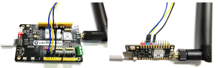
- Prepare a USB Type-C cable and an ST-LINK. Connect the Type-C cable to the Type-C port for power and serial communication and connect the ST-LINK to the SWD pins like this:
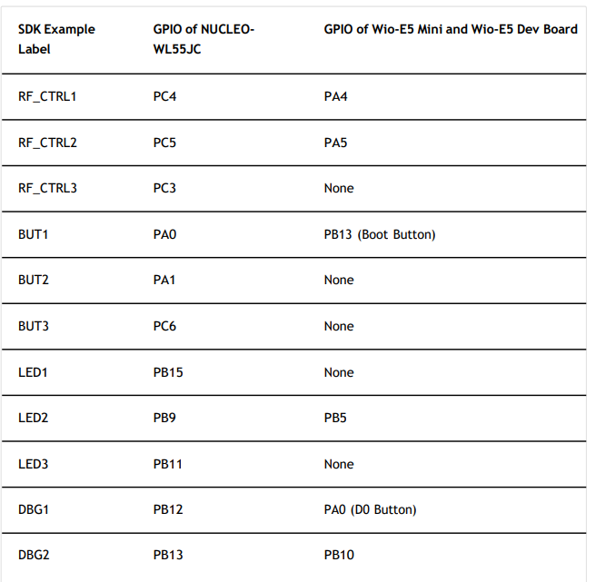
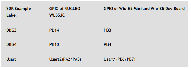
GPIO Configuration Overview
As the hardware design of the Wio-E5 series is a bit different from NUCLEO-WL55JC, the official STM32WL55JC development board from ST, developers need to reconfigure some GPIOs, to adapt the SDK example to the Wio-E5 series. We have already reconfigured gpios in this example, but we think itis necessary to point out the difference.
Build the LoRaWAN End Node Example
- Download and copy this repo to your SDK folder. stm32cubewl\SIM32Cube_FW_WL_V1.0.0\Projects\NUCLE0-| VL55JC\Applications\LoRaWAN and replace the original en. stm32cubewl\STM32Cube_FW_WL_V1.0.0\Projects\NUCLE0- WL55JC\Applications\LoRaWAN\LoRaWAN_End_ Node folder
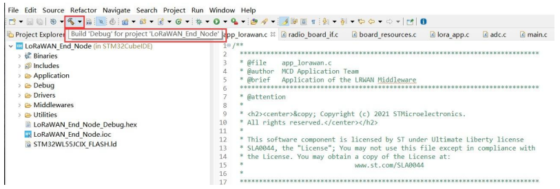
- Open the LoRaWAN_End _Node example with sTM32CubeIDE, by double click file LoRaWAN_End_Node\STM32CubeIDE\.project
- Click Build Debug for this example; it should work without any errors.
Application KEY, and your LoRaWAN Region
Modify your Device EUI, Application EUI, Application KEY, and your LoRaWAN Region
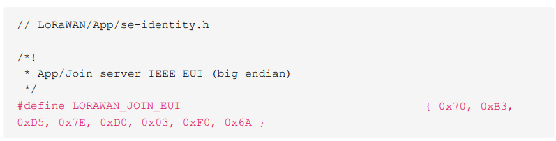
- Please follow the guide here to set up your TTN application, get yourApplicationl and copy it to the macro definition LORAWAN_JOIN_EUI in LoRaWAN/App/se-identity.h, for example, my Application EUI is 70 B3 DS 7E DO 03 FO 6A.
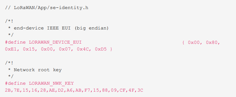
- Also, you can modify your DeviceEUI and Application Key, b setting the macro definition LORALORAWAN_DEVICE_EUI LORAWLORAWAN_NWK_KEYoRaWAN/App/se-identity.h, don’. Don’tt to ensure LOLORAWAN_DEVICE_EUInd LOLORAWAN_NWK_KEYre the same as the Device BUI and App Key in the TTN console.
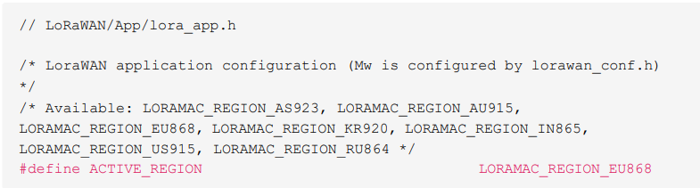
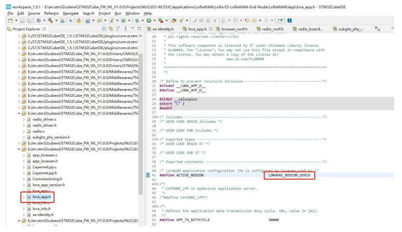
- The default LoRaWAN Region is EU868; you can modify it by setting the macro definition ACTIVE REGION in LoRaWAN/App/lora app.h
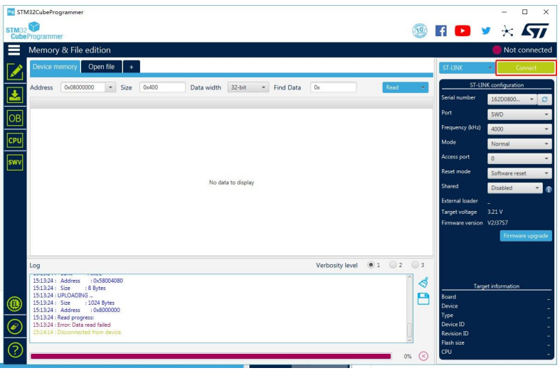
- After modification, please rebuild the example and program for your Wio-E5. Open STM32CubeProgrammer, connect ST-LINK to your PC, hold the RESET Button of your Device, then click connect and release the RESET Button.
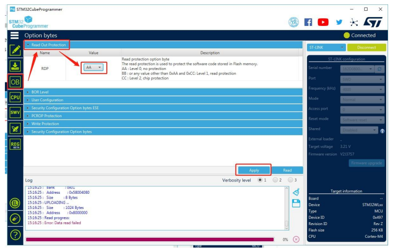
- Make sure the Read Out Protection is AA. If it is shown as BB, select AA and click Apply.
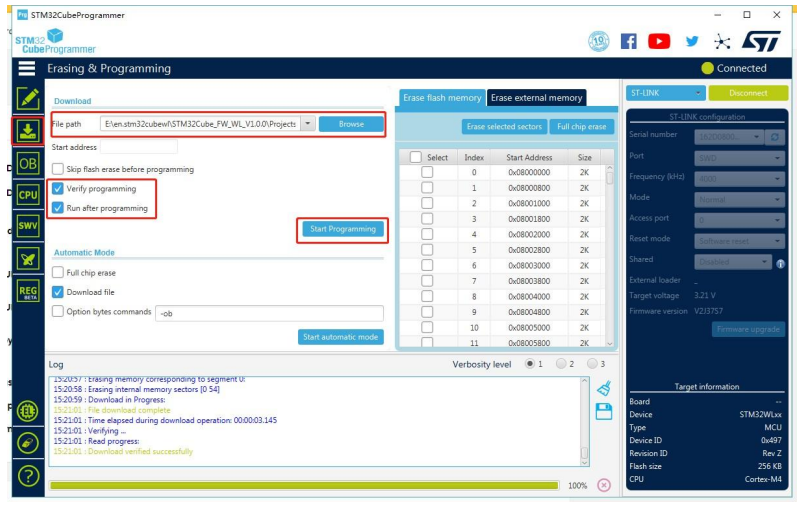
- Now, go to the Erasing & Programming page, select your hex file path(my path is
E: \en.stm32cubewl\STM32Cube_FW_WL_V1.0.0\Projects\NUCLB0-| WLSSJC\Applications\LoRaWAN\LoRaWAN_End_Node\STM32CubeIDE\LoRaWAN_End_Node_D_ End Node_D ebug. hex ), select the programming options as the following picture, then click Start Programming! Oncethe programming is finished,
- If your LoRaWAN Gateway and TTN are set up, Wio-E5 will join successfully after a reset! A Acomfirm LoRaWAN package will be sent to TTN every 30 seconds. The following log will come out from the serial port if the join is successful:
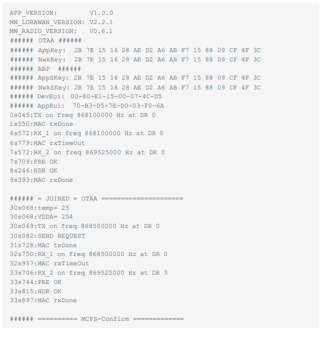
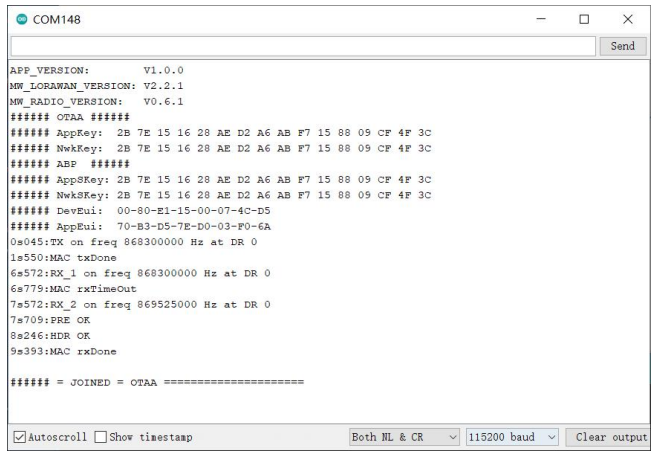
- Cheers! You have already connected Wio-E5 to the LoRaWAN Network! Can’t wait to see you develop some wonderful LoRaWAN End Node applications!
Application Notes
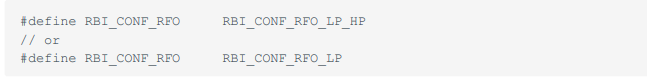
Wio-E5 only supports high power output mode, so you can’t use these macro definitions in radio_board_if.h
Specification
The following specifications apply to the Seeed Studio Wio-E5 TM32WLE5JC Wireless Module, ensuring reliable LoRaWAN and CAN/RS485 performance for IoT applications:
- Voltage supply: 5V/USB, 3.7V Lipo Battery, 4.5~28V DC input
- Voltage output: 3.3V
- Power output: Up to 20.8dBm at 3.3V
- Frequency: EU868 / US915 / AU915 / AS923 / KR920 / IN865
- Protocol: LoRaWAN
- Sensitivity: 116.5dBm ~ -136dBm
- Modulation: LoRa, (G)FSK, (G)MSK, BPSK
- CAN 2.0 speed: Up to 1Mb/s
- CAN FD speed: Up to 5Mb/s
Tech Support
Please submit any ttechnical issues toour forum.
Customer Support
- Website: www.seeedstudio.com
- Ph: +86-0755-86095676
2008-2025 Seeed Technology Co., Ltd. All rights reserved.
FAQs
Q. Does the Wio-E5 support LoRaWAN® Class A/B/C devices?
Indeed. The Wio-E5 is compatible with the majority of public and private LoRaWAN® networks, including Helium, ChirpStack, and The Things Network (TTN), and it supports LoRaWAN® Class A, B, and C modes.
Q. Can I use the Wio-E5 as a standalone MCU?
The Wio-E5 doesn’t need an external microcontroller to function. The STM32WLE5JC core can be used to write firmware for LoRaWAN communication, control logic, and data acquisition.
Q. Can I integrate Wio-E5 with Arduino boards?
With AT commands, the Wio-E5 module can be used with any Arduino board via UART. An Arduino Library offered by Seeed Studio makes LoRaWAN® connectivity easier.
Q. Does the Wio-E5 support encryption and security?
Indeed. For both uplink and downlink communication, it supports LoRaWAN AES-128 encryption, guaranteeing data security and integrity across networks.
Q. What are the typical data rates supported?
From SF12/125 kHz (long range, low speed) to SF7/250 kHz (short range, high speed), the Wio-E5 can support LoRaWAN data rates DR0 to DR7 (region-dependent).
Q. How do I debug or monitor LoRa communication?
To view AT responses and logs in real time, use a serial terminal (such as PuTTY, CoolTerm, or Arduino Serial Monitor) set to 115200 baud.
Q. Can I use the Wio-E5 with a custom LoRaWAN gateway?
The majority of gateways that support LoRaWAN 1.0.3 can be used with the Wio-E5. For integration, you can use open-source servers like RAK LoRa Server, TTN, or ChirpStack.
1 Comment
Pingback: Seeed Studio BM3301–1216 BLE 5.4 Wireless Module User Guide