
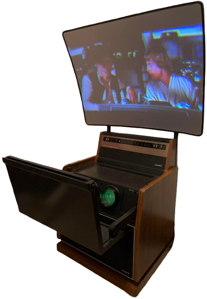
Sony KP-5000 Color Video Projector
Introduction
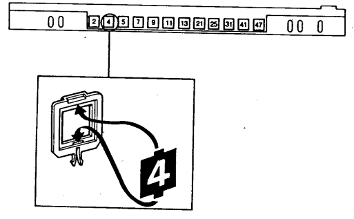
The Channel Indicators 2 through 13 are pre-adjusted at the factory to VHF channels 2-13. This results in blank positions interspersed with regular TV channels. Those positions may be used to receive local TV stations in your area. Any channel position can be set up to receive any local station, VHF or UHF.
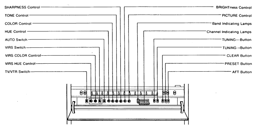
Parts & Controls
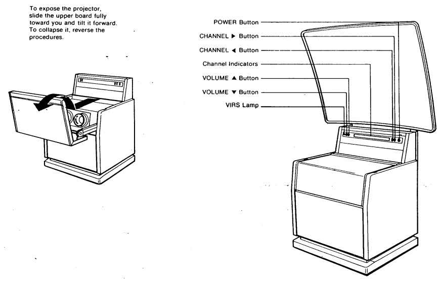
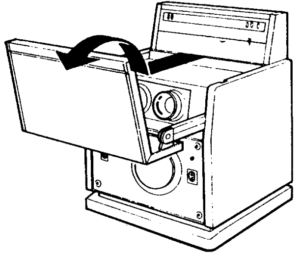
To expose the projector. Slide the upper board fully toward you and tilt it forward. To collapse it, reverse the procedures.
Prepration
Screen Installation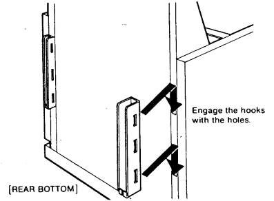
• Attach the metal fittings on both sides. 2-2 Install the screen supports into the extension arms and secure with the two 6 mm dia. shorter wing screws supplied.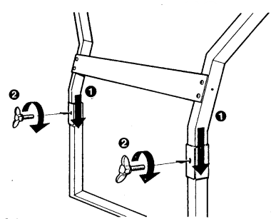
For 72-Inch screen
2-1 Install the extension arms into the fittings and secure with the two 8 mm dia. longer wing screws (supplied). Install the crosspiece and the four 4 mm dia. wing nuts (supplied). Leave the nuts loose. After the following 2-2 procedure, secure the nuts.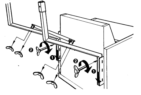
Engage the hooks on the rear of the screen with the support rod.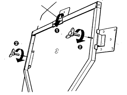
To secure the stability of the apparatus nstall the support assembly at the rear bottom of the projector and secure it with the two 8mm dia. wing screws supplied as illustrated.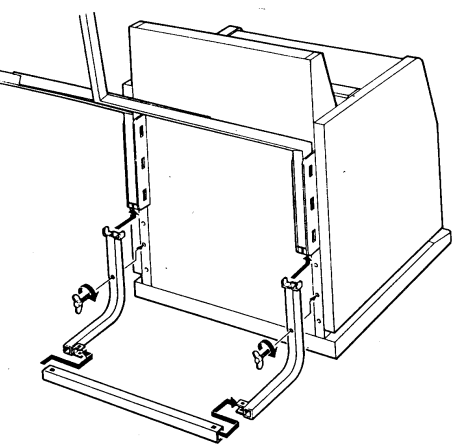
Power Connection
The KP-5000 and KP-7200 operate on 120V, 60Hz. Connect the Power Cord (rear) to a 3-wire 120V ac wall outlet.
- Antenna Connection: For the best TV reception, the use of an outdoor antenna is recommended.
Connections
VHF Antenna Terminals
When using 300-ohm ribbon-type lead-in wire, set the Terminal Switch to the 300 S position. To connect the wire to the VHF antenna terminals, strip the plastic insulation from the end of the lead-in wire, loosen the nuts on the terminals, wrap the bare copper leads around the terminals, then tighten the nuts. When using 75-ohm coaxial cable, set the Terminal Switch to 75 N. The connection can be made with an optional type F antenna connector.
UHF Antenna Terminals
The Terminal Switch does not affect this connection. The connection to the UHF antenna terminals can be made in the same manner as explained for the VHF antenna connection. For UHF antennas using 75-ohm coaxial cable, the EAC-13W External Antenna Connector (optional) permits convenient connection. This plugs directly into the UHF terminals and accepts an op tional type F connector.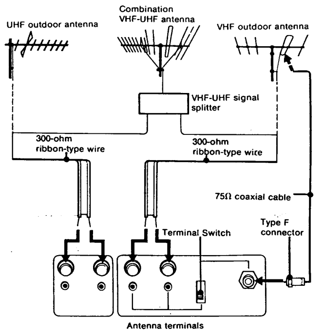
Registration Adjustment
After transporting the set from one place to another, the red, green, and blue lines may not be superimposed. If this symptom is noticed, perform the registration adjustment yourself. Should the difficulty persist, contact your Sony dealer.
Preparation
- Complete the connections indicated in the instruction manual.
- Remove the front grille and push in the TEST/NORMAL Button (TEST position).
- Slide the upper board fully toward you and tilt it forward.
- Press the POWER Button to switch on the system. A built-in cross-hatch pattern will be displayed on the screen.


Adjustment
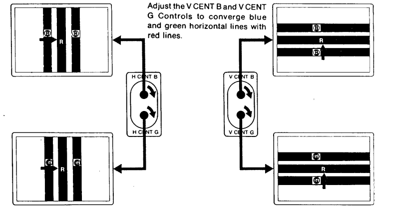
As you turn the controls clockwise, the lines move in the direction indicated in the illustrations. To move the lines in the opposite direction, turn the controls counterclockwise.
- Adjust the H CENT B and H CENT G Controls to converge blue and green vertical lines with red lines.
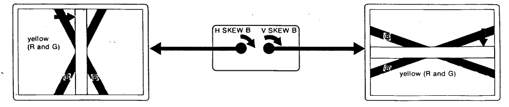
- Adjust the HSKEW B Control to converge blue vertical lines with red and/or green lines. Just the y SKEW B Control to converge blue horizontal lines with red and/or green lines.
- Repeat the steps ® and ®. After the adjustment is completed, push to release the TEST/NORMAL Button and replace the front grille.
Channel Presettings
Your Sony self-contained video tuner uses an electronic tuning system that is capable of receiving up to 12 television channels. Once you preset the channels, any channel can be selected either by pressing the CHANNEL • or 1 Button, or by using the hand-held remote commander (See “REMOTE CONTROL OPERATION”).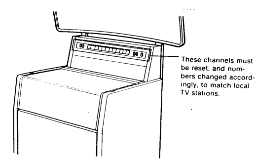
Selecting the Station
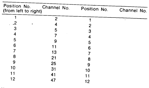
Determine and list which channels (up to 12) are to be set, and the order in which you would like them arranged. Consult your local TV listings to find out the channels in use (“active”) in your area. Suppose that the following channels are active in your city: VHF: Channels 2, 4, 5, 7, 9, 11, and 13 UHF: Channels 21, 25, 31, 41, and 47 • Then the positions would be arranged (in numerical order for convenience) as follows: Enter your channel numbers below.
Channels
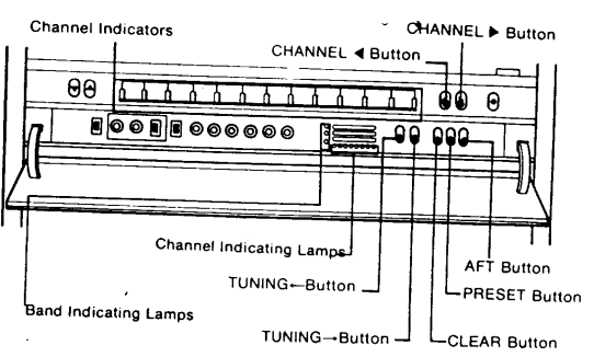
Press the POWER Button to switch on the projector. Open the front compartment lid to expose the presetting controls. Set the TV/VTR Switch to TV.
- Tune in position 3 with the CHANNEL ( • ] Button.
- Depress the PRESET Switch to ON. Tune in the VHF Channel 3 (position 2) with the CHANNEL [* ] or (1 ] Button.
- The red Band Indicating Lamp and the leftmost Channel Indicating Lamp will light.)
- Press the TUNING (-*) Button again. (Tuning will continue automatically until the second lowest. numbered channel – Channel 4 in our example – is received.
- The red Band Indicating Lamp and the Channel Indicating Lamp(s) in the center will light.)
- Tune in position 3 with the CHANNEL [ P] Button. (The position 2 picture will appear.)
- Press the TUNING [→) Button. The third lowest-numbered channel – Channel 5 in our example -\ will be received.)
Operation
To switch on the TV
Press the POWER Button. The picture will appear in a few seconds. (To switch off, push the button again.
To adjust the sound
Depress the VOLUME [4] Button. To decrease, depress the VOLUME (y ] Button. To obtain the desired tone quality, adjust the TONE Control. For more treble, turn it clockwise; for less treble, turn it counterclockwise.
To operate in the automatic mode
Set the AFT Button, AUTO Switch, and VIRS Switch to ON.
To Select a Channel
Depress the CHANNEL (*] or (4) Button. Each momentary press of the [P] Button changes one channel from left to right, and the[(4] Button changes one channel from right to left. The selected channel number will light. (Soe “CHANNEL PRESETTING” on page 7.)
- To fine-tune the channel, set the AFT Button to OFF and press the TUNING (→] or (*-) Button to obtain a clear picture.
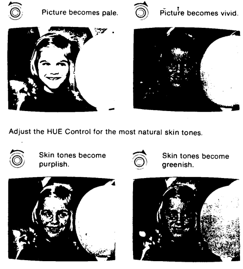
To adjust brightness and contrast
Correct brightness and contrast settings are important for good color reproduction. The PICTURE Control will adjust the contrast, color intensity, and brightness simultaneously in the proper ratio. Perform the initial adjustments as follows.
- Turn the PICTURE Control fully counterclockwise.
- Adjust the BRIGHTness Control for the desired brightness level.
- Adjust the PICTURE Control from the lowest setting to the desired level by turning it clockwise, to suit personal preference and room lighting conditions.
Colour Adjustment
- When the VIRS Lamp is off, both COLOR and HUE Controls have a limited adjustment range in the AUTO mode. If you wish to control color reproduction manually, set the AUTO Switch to OFF to disengage the automatic mode. Adjust the COLOR and HUE Controls to suit your preference.
Adjust the COLOR Control for the desired color intensity.
- The COLOR and HUE Controls do not function when the TV is receiving a VIR signal. If you wish to control color reproduction manually, adjust these controls.
- The VIRS COLOR and VIRS HUE Controls function the same as the COLOR and HUE Controls described previously. However, the adjustment range is more limited.
Remote Control
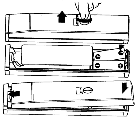
Installing batteries into the Sony Remote Commander
- Remove the screw on the back by turning it with a coin or similar object, and open the cabinet.
- Install the two supplied size “AA” batteries (IEC Battery Designation R6) in the battery compartment.
- Close the cabinet and fasten it with the original screw.
- In normal operation, battery life is up to half a year.
- In normal operation, battery life is up to half a year.
Operation
Before operating the TV with the Remote Commander, first complete the tuning, color, and picture adjustments as previously described.
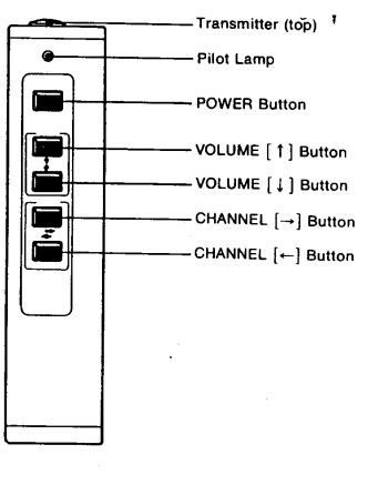
- Hold the Commander with the Transmitter (top) pointed at the screen. You can operate the Commander anywhere up to 7 meters (23 feet), and withina 30° angle from the center of the screen.
- To turn the projection system on or off, depress the POWER Button.
- You can adjust the sound volume with the VOLUME Buttons.
- To increase the sound volume, depress the VOLUME [ f] Button.
- To decrease it, depress the VOLUME | + ] Button.
- Select the desired channel by depressing the CHANNEL I] or [~] Button.
Notes on the Remote Commander
- Keep the Commander away from extremely hot or humid places.
- Be careful not to allow foreign objects to fall into the cabinet, particularly when replacing batteries.
- To avoid a malfunction, do not simultaneously depress two or more buttons.
Video Tapes
VTR connection
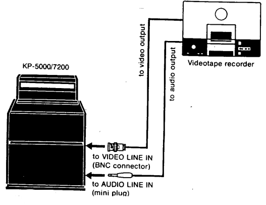
Set the TV/VTR Switch to VTR. Power, volume, me, and picture adjustments (PICTURE, BRIGHTness, C, L, OR, and HUE Controls) are the same as for TV viewing. With the VIRS Switch on, oversaturation (excessive color) may appear in the playback picture on the screen. In this case, set the VIRS Switch to OFF and adjust color and hue manually.
Specifications
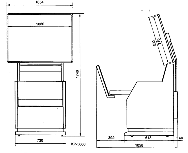
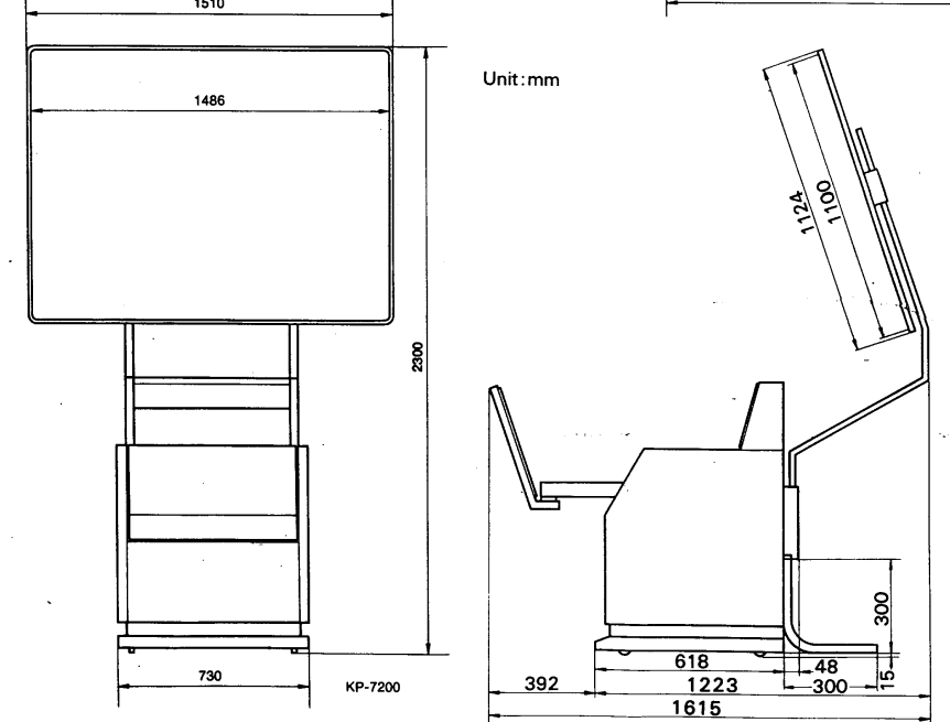
- Projected picture size:
50″ diagonally (КP-5000) 72″ diagonally (KP-7200) - Viewing distance: 12 ft. (3.6 m) minimum to 60 ft. (18.3 m) maximum for KP-5000, 16 ft.
- Color picture light source: Three monochrome picture tubes specially designed for projection use
- Television system: American TV standards
- Channel coverage: VHF channels 2 – 13, UHF channels 14 – 83.
- Antenna: 300-ohm external antenna terminals for VHF and UHF, 75-ohm external antenna terminal for VHF
- Projected picture brightness: More than 60 fL (white peak) (KP-5000), More than 30 fL.
- Projected contrast: Ratio More than 30:1 (in darkened room)
- Video input: NTSC color signal, 1V (p-p) sync negative, 75 ohms
- Weight: 0.775Vrms, high impedance 20 cm (8 inches) dia 120V ac, 60 Hz 258 W (max), 213 W (average)
- Remote Commander: RM-601W 50-inch (KP-5000) or 72-inch (KP-7200) screen.
- Dimensions: 44 x 27.5 x 192 mm (w/h/d) (1¾ × 1⅛ × 7⅝ inches)
- Weight: Accessories supplied Screen
- Weight: 165 g (6 oz), excl. batteries
Dimensions
Disposal
For the Customers in Europe
The recycling of materials will help to conserve natural resources. For more detailed information about the recycling of this product, please contact your local Civic Office, your household waste disposal service, or the shop where you purchased the product.
Notice for the customers in the countries applying EU Directives > Manufacturer: Sony Corporation, 1-7-1 Konan Minato-ku, Tokyo, 108-0075 Japan. For EU product compliance: Sony Belgium, bijkantoor van Sony Europe Limited, Da Vincilaan 7-D1, 1935
For the Customers ithe n the Republic of India
Reduction in the Use of Hazardous Substances in Electrical & Electronic Equipment. This product and its components, consumables, parts, or spares comply with the hazardous substances restriction of India’s E-Waste (Management) Rules. The maximum allowable concentrations of the restricted substances are 0.1% by weight in homogenous materials for Lead, Mercury, Hexavalent Chromium, Polybrominated Biphenyls (PBB) and Polybrominated Diphenyl Ethers (PBDE), and 0.01% by weight in homogenous materials for Cadmium, except for the exemptions specified in Schedule II of the aforesaid Rules.
Customer Service
- Website: https://www.sony.com/
- Ph: 800-326-9551