
Yuneec Tornado H920 Plus Drone
INTRODUCTION
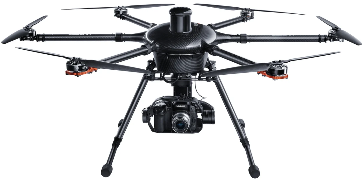
The H920 Plus is a professional multirotor aerial photography and videography platform. Its unique and innovative features make it possible to capture amazing photographs and video footage for a variety of uses. The modular aircraft platform is compatible with CGO4 Camera,a 3-Axis Stabilized Gimbal System.
Safety Instructions
- Keep your hands, face, and other parts of your body away from the spinning propellers/rotor blades and other moving parts at all times.
- Keep items that could impact or become entangled away from the propellers/rotor blades, including debris, parts, tools, loose clothing, etc.
- Always operate your aircraft in open areas that are free from people, vehicles, and other obstructions. Never fly near or above crowds, airports, or buildings.
- Always keep a safe distance in all directions around your aircraft to avoid collisions and/or injury.
- This aircraft is controlled by a radio signal subject to interference from many sources outside your control. Interference can cause momentary loss of control.
- Always operate your aircraft when the voltage of the battery in the transmitter/personal ground station is in a safe range (as indicated by the battery charge status icon on the screen of the transmitter/personal ground station).
- Always keep the aircraft in clear line of sight and under control, and keep the transmitter/personal ground station powered on while the aircraft is powered on.
- Always move the throttle control stick down fully and turn off the motors in the event the propellers/rotor blades come into contact with any objects.
- Always allow components and parts to cool after use before touching them and flying again.
- Always remove batteries after use and store/transport them per the corresponding guidelines.
- Never place any portion of the aircraft or any related accessories, components, or parts in your mouth, as doing so could cause serious injury or even death.
- Carefully follow the instructions and warnings included with this aircraft and any related accessories, components, or parts (including, but not limited to, chargers, rechargeable batteries, etc.).
Content Package
The H920 PLUS RTF includes everything necessary to fly. Yuneec offers a variety of imaging products; there may be other enhancements available to suit a specific purpose
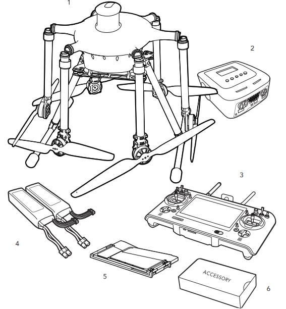
- H920 Plus RTF Airframe (4 sets of Propeller/Rotor Blade)
- A10 Charger
- ST16 Transmitter and Personal Ground Station
- 4000mAh 6S 22.2V LiPo Battery (2pieces)
- ST16 LCD Screen Sun Shade/Shield
- ACCESSORY Box
Flight Battery
Connecting to the power source : the A10 Dual Balance Charger comes with built in switching power supply. You can connect the AC power cord directly to the main AC socket (110 to 240V AC).
NOTICE: While the A10 is connected to a suitable 110 to 240V AC power source, the combined power output for Channel A and Channel B is 200W, capable of charging two 6-Cell (6S), 4,000mAh LiPo battery packs at 4.3A.
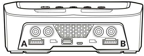
Connecting the Battery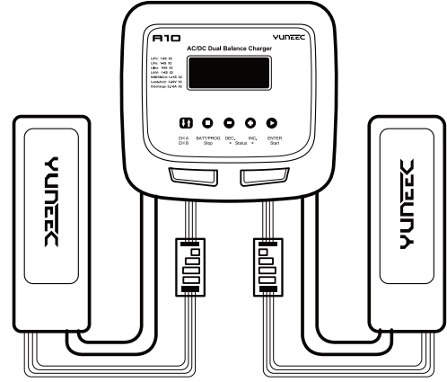 Button Description
CH A / CH B: Used to switch from Channel A to B or Channel B to A. BATT PROG / STOP: Used to stop the progress or go back to previous step/screen DEC: Used to go through the menus and decrease the parameter value. INC: Used to go through the menus and increase the parameter value. ENTER / START: Used to enter parameter or store parameter on screen.
Charging
Batt/program select: press inc and dec to go through all the programs and press start/enter to enter lipo batt program (for flight batt) or li-ion batt program(for proaction™). Mode select: press inc and dec to go through all the modes and press start/enter to enter lipo balance charge mode (for aircraft’s flight battery), to enter li-ion balance charge mode (for proaction ground handle). Battery setting: press start/enter, the current value will start to blink, press inc and dec to change the value and press start/enter to confirm your setting. For the H920 Plus battery, it is recommended to set 4a (no more than 8a).
For the proaction™ battery, it is recommended to set 2a (no more than 3a). At the same time, the battery cells number will start blinking, press inc and dec to change the value and press start/enter to confirm your setting. For the H920 Plus battery, 6s should be selected. For proaction™, 4s should be selected. Program start: Press and hold start/enter for 3 seconds to start the program. The charger is detecting the battery cell
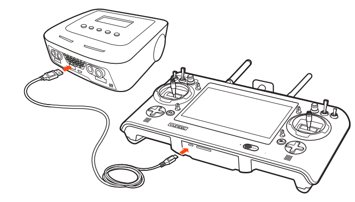
The ST16 battery is charged by using the supplied USB cable and inserting it into the USB port in the charger. It will take approximately five (5) hours to charge a fully discharged (not over-discharged) battery.
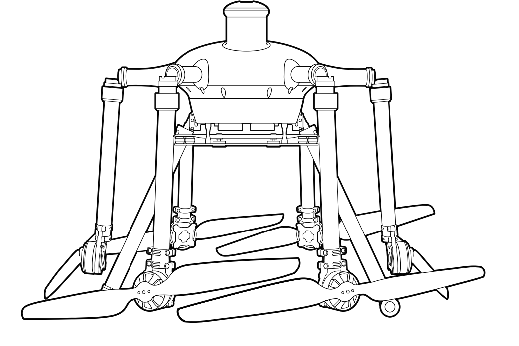
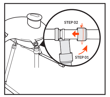
Motor Arms
Fold the motor arms upwards and secure them using the straight knurled nut cover located on the motor arms.
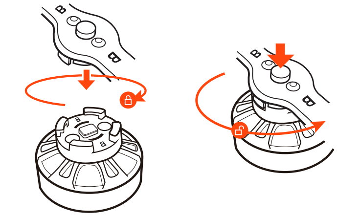
Propellers
Mount the propellers on the motors properly and note the ‘A’ and ‘B’ printed on the motor arms. This distinction between ‘A’ and ‘B’ refers to propeller ‘A’ and ‘B’. Mount propeller ‘A’ on motor ‘A’ and propeller ‘B’ on motor ‘B’. Press and rotate the propeller in the reverse direction the arrow indicates. When a click is heard, the propeller is successfully secured. After securing the propeller, hold the motor housing with one hand while attempting to turn the prop in both directions to ensure and check for a complete lock.
Installations
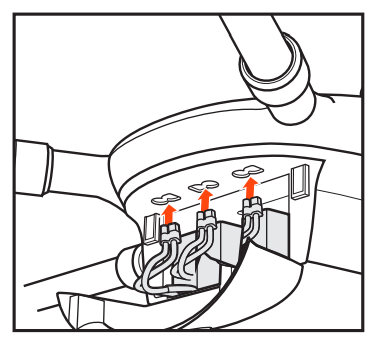
After the flight batteries have been fully charged, they are ready to be installed in the H920 PLUS:
- STEP 1) Open the battery compartment flap with the status LED mounted on it by carefully pulling the top edge of the door flap.
- STEP 2) Slide the batteries into the compartment with the EC3 blue, polarity-protected connector leads/wires towards the downward side of the compartment.
- STEP 3) Connect the flight battery to the relevant socket above the respective battery on the H920 PLUS using the EC3 blue, polarity-protected connector.
Flight Controls
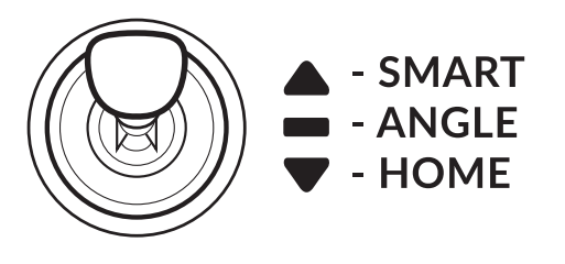
The ST16 is equipped with 3 different flight modes, which can be selected using the mode switch in the top right corner above the right joystick.
Smart Mode
If the Flight Mode selection switch is fully up, then the H920 Plus is in Smart Mode. Although we recommend learning how to fly as soon as possible in Angle Mode, Smart Mode is the best choice for low-time pilots when test flying. In Smart Mode, the H920 Plus always flies in the direction in which the right joystick (mode 2) is moved by the pilot, regardless of the direction in which the nose is pointing. So if you move the stick to the right, the H920 Plus will also move to the right regardless of the position of the nose, even if it is in the middle of turning. The mode can also be useful to pilots who have lost their bearings when flying in Angle Mode.
Additional Smart Mode Features
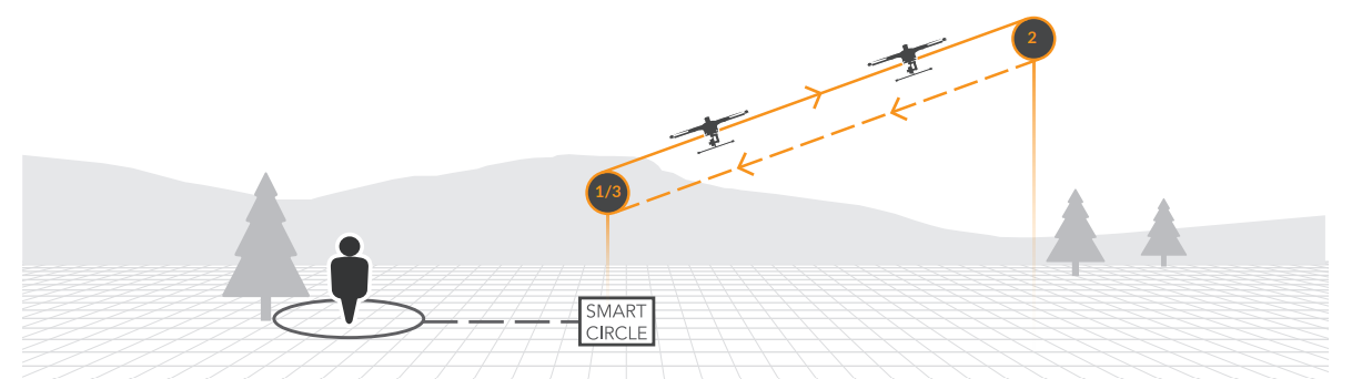
SMART CIRCLE: In most cases, the Smart Circle will keep the H920 Plus approx. 8m / 26 ft. away from you, provided you are positioned 8 m /26 ft. behind the H920 Plus.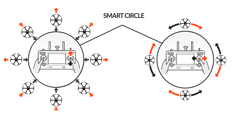
We recommend that you take your time learning how the H920 Plus responds to various control inputs while flying. In Smart Mode, the H920 Plus will always move in the direction the right-hand control stick is pushed relative to the pilot, and no matter which way the front/nose is pointed. In Angle (Pilot) Mode, the H920 Plus will move in the direction the control stick is pushed relative to the front/nose of the aircraft (and the ‘angle’ of movement is determined by how far you push the stick away from the centre position).
Angle Mode
If the Flight Mode selection switch is in the centre position, then the H920 Plus is in Angle Mode. Angle Mode is designed for pilots with a little experience (those who have already mastered Smart Mode), because in this mode the H920 Plus moves in line with the joystick, in the direction in which the nose is pointed.
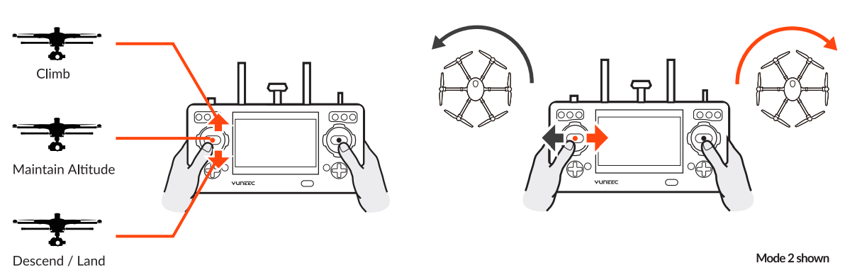
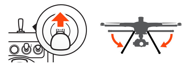
To take off/launch, first start the motors in angle mode, then slowly raise the left-hand stick to slightly above the centre position. The H920 PLUS will take off and climb slowly (push the stick further upward if the H920 doesn’t take off). Release the stick to return to the centre position when the H920 PLUS reaches the desired altitude. The H920 should hover in place.
Extra Angle Mode Features
Position Freely and Retain Altitude
The H920 PLUS will hold its position automatically when GPS is enabled (if there is sufficient GPS signal), and it will retain the altitude level if the left stick is in the middle\ position.
Retracting and Lowering the Retractable Landing Gear
The H920 PLUS’s landing gear is to keep it out of frame when a camera is attached. Landing gear may be retracted by switching up the Landing Gear Switch on the top right side of the ST16. Be certain to flip the switch to the downward position when landing.
Landing
Position the H920 PLUS above the landing area. Slowly lower the left-hand stick to below the centre position. The H920 PLUS will slowly descend and land. After the H920 PLUS lands, depress and hold the START/STOP button for approximately two seconds to stop the motors. Alternatively, activate Home Mode and the H920 PLUS will automatically fly back to the home point and will land within an 8m/26’ diameter circle around the Ground Station.
AFTER LANDING — ALWAYS turn off the H920 PLUS BEFORE turning off the ST16. Then remove the battery(s) from the H920 PLUS and allow it to cool to ambient/room temperature before recharging
Control Rate Slider
The Proportional Control Rate Slider, located on the right side of the ST16 Ground Station, allows the overall climb/descend and directional control rates to be controlled. Use the slow (turtle) position for the lowest control rates (best for first-time pilots and required when flying between 5000 feet and 8000 feet Above Mean Sea Level), and use the high-speed (rabbit) position for the highest control rates (best for experienced pilots and can only be used when flying 5000 feet MSL below). Speed is variable between Slow and Fast modes.
Home Mode
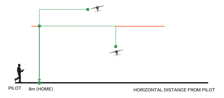
If H920 PLUS loses the link with the ST16 Ground Station, it will automatically enter Home Mode. Before switching to Home Mode, press the Setting Calibration button on the right task column. Select Home Altitude and set an altitude as the desired altitude, and then Home Mode can be activated. The flight path is as follows: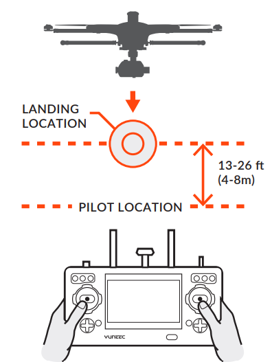
- When the flight altitude of the aircraft is lower than the desired altitude, it will climb to the desired altitude vertically first, then fly back at the current altitude and descend vertically within 13-26ft(4-8m) of the pilot until it automatically lands.
- When the flight altitude of the aircraft is higher than the desired altitude, it will fly back at the current altitude, then descend vertically within 13-26ft (4-8m) of the pilot until it lands automatically.
Additional Functions
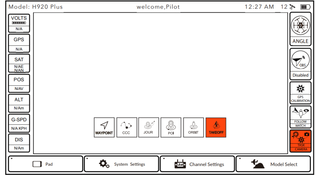
Task Modes
Tap the TASK/CAMERA icon, the background of ‘TASK’ will become orange, then the menu opens another interface displaying functions: WAYPOINT, CCC (Curve Cable Cam), Journey, POI (Point of Interest), ORBIT ME and TAKE OFF. CCC: (Curve Cable Cam) Curve Cable Cam allows creation of a flight route/mission – H920 PLUS to flv. Once for H920 PLUS to fly. Once the pilot sets the points, H920 PLUS will fly the set coordinates while remembering the heading.
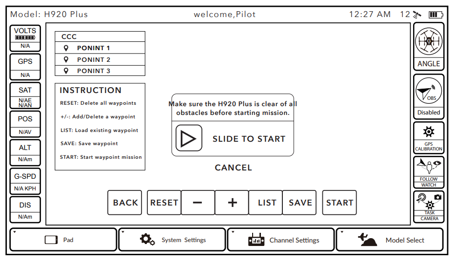
Tap the CCC to enter the Curve Cable Cam function. BACK: Tap BACK to return to the previous interface. RESET: Tap RESET to delete all the points created during the flight. to delete the last point created during the flight. to create a new point recording the current flying position. Delete any saved mission/route by sliding the chosen one to the left. START: Tap START, and slide the icon. H920 PLUS will fly back to waypoint 1 automatically.
Back Reset List Save Start
[ ]: When the pilot taps the [ ], the icon will become [ ]and the CCC function will be paused. When tapped again, the [ ] will become [ ], and the copter will continue the CCC function. Exit the function by tapping EXIT icon or switching flight mode.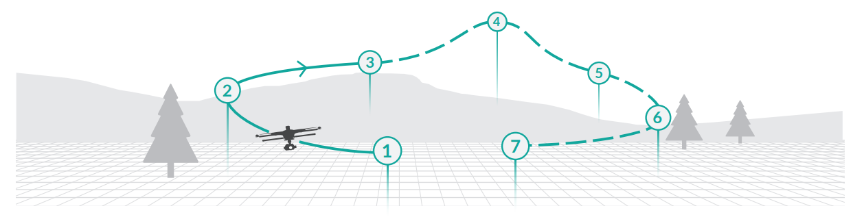
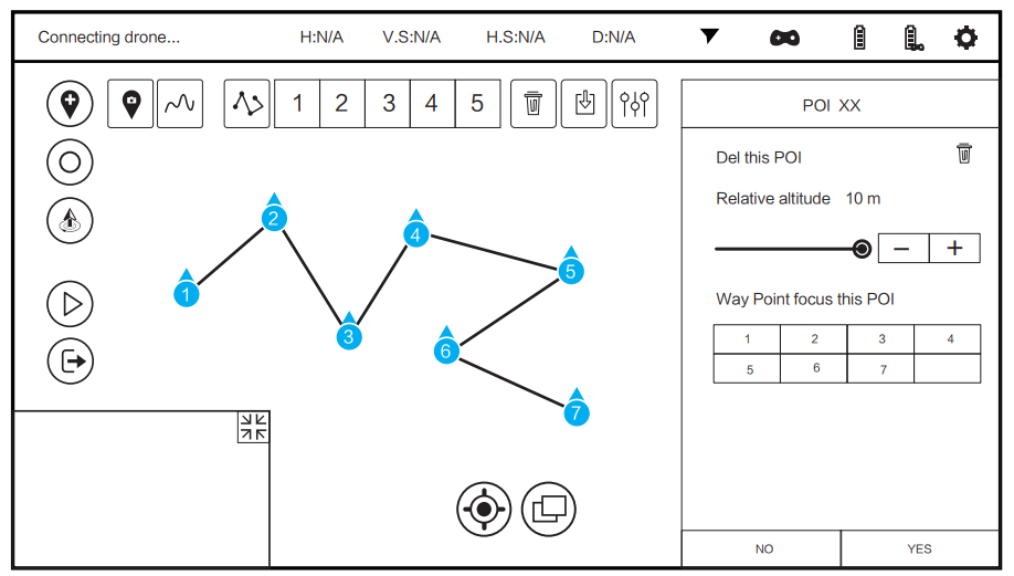
If the pilot sets 7 waypoints as shown, when the copter arrives at Waypoint 1, slowly raise the throttle stick, and the copter will fly along the waypoints from 1 to 7 in order. If the pilot slowly lowers the throttle stick, the copter will fly along the waypoints from 7 to 1 in order
Journey Point
- START: Select JOUR and set the distance, then slide the slider. H920 PLUS will fly up and out to take a photo or video.
- BACK: Tap BACK to return to the previous interface.
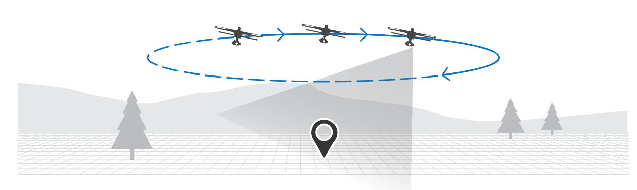
- ORBIT ME: When Orbit Me is enabled, H920 Plus flies a circular path around the pilot. Press ORBIT to enter the ORBIT ME function.
- SARI: Press SIAR!, and slide the icon, push the alleron stick to the right or left.
- BACK: TaS BACK to return to the previous interface.
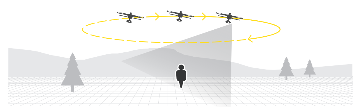
To select a subject to be orbited and have the H921 subject. CENTER: Press CENTER to set the current flight position of H920 Plus as the centre of a circle. START: Press SlARI, and slide the icon, push the aileron stick to the right or left, H920 Plus will fly around the circle centre with a distance between the Start point and the centre point as the radius.
Take Off
When there is a suitable GPS signal for both the aircraft and ST16, and the aircraft is in Angle or Smart (chosen ‘Follow’) mode, the function of taking off the aircraft by one slide can be activated with the aircraft flat on the ground.
- STEP 1) Press TASK/CAMERA, select TAKE OFF;
- STEP 2) Slide the sliding block from left to right, the aircraft will climb vertically and begin to hover until it reaches about 6.6 feet high.
Waypoint
Waypoints are an intelligent function, including mission/route-planning function, geo-fence function and takeoff/point-to-land function. A waypoint defines a specific location and behaviour at a specific point in time, allowing for intelligent auto-functions during flight.
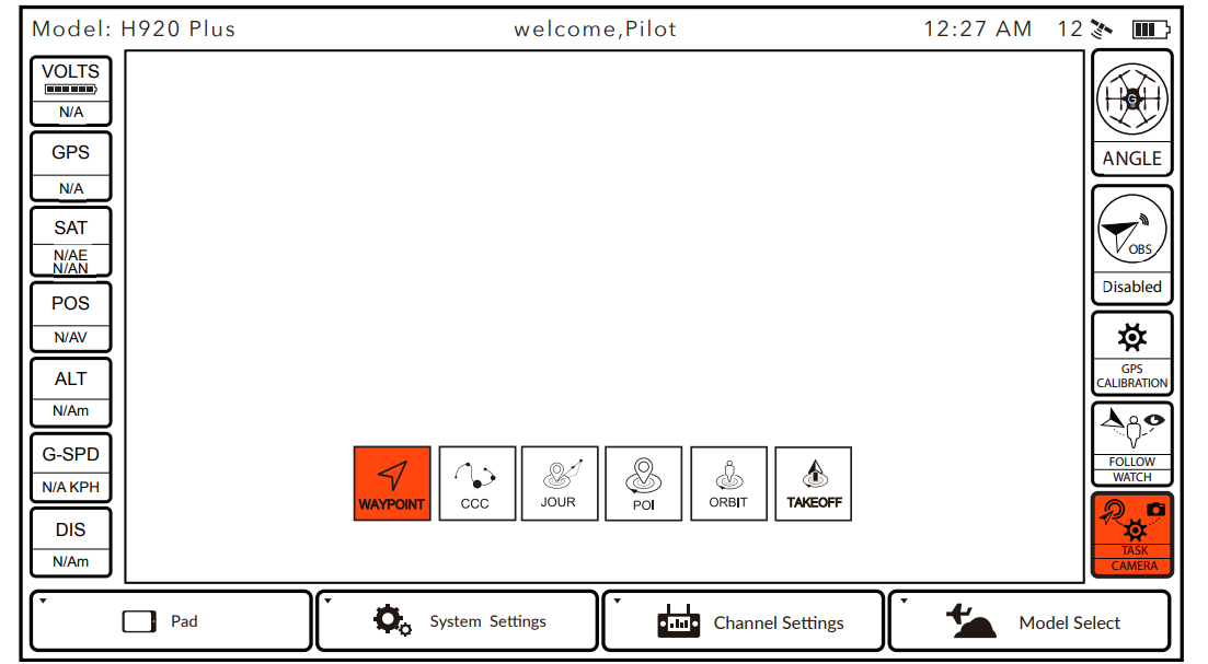
- STEP 1) Select TASK/CAMERA in Angle mode, select “WAYPOINT.”
- STEP 2) Choose “OK” to accept any pop-up warnings/alerts, and to access the WavPoint interface.
Map Preparation
The map will match the ST16’s menu-selected language (if English is selected, the map will be Google Maps automatically). The settings icon [ ] may also be tapped on the right top corner of the screen, and then tap the icon [ ] to switch the map manually. To download maps, follow the steps below:
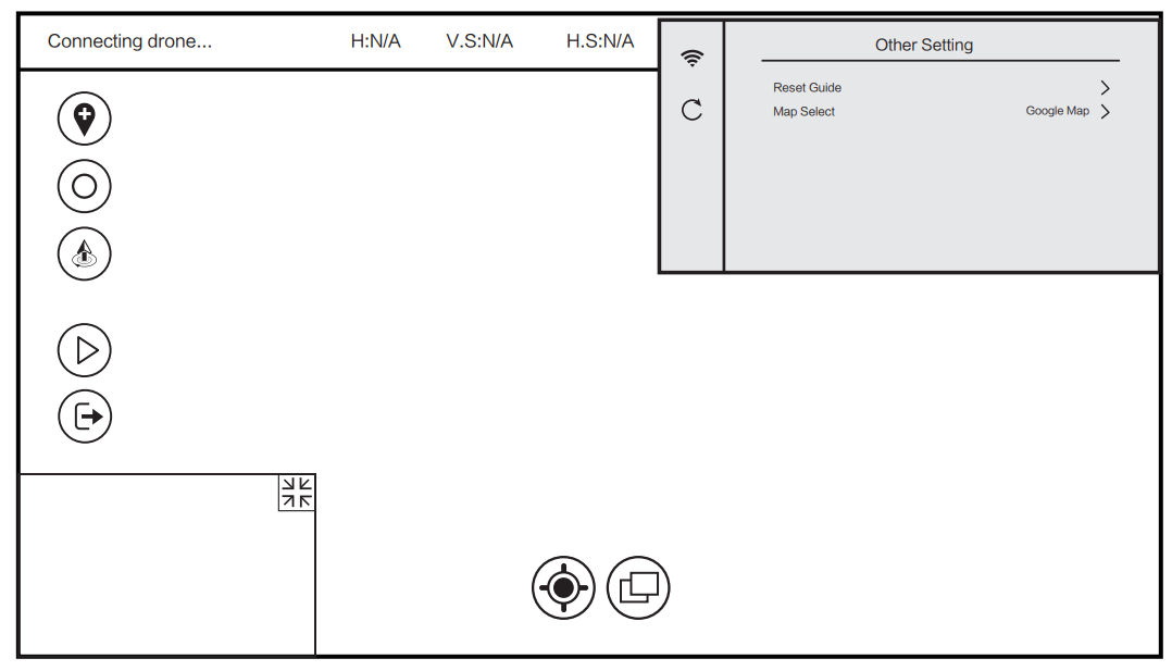
- STEP 1) Power on the ST16, and then lock the GPS signal (For a better connection, we recommend you go outdoors).
- STEP 2) Tap the setting icon | @ lon the right top corner, then select the Wi-Fi icon [ = Jand connect to the available network.
- STEP 3) The map will be downloaded automatically based on location.
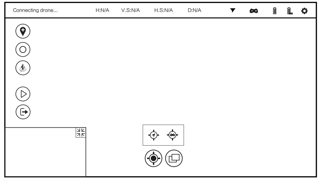
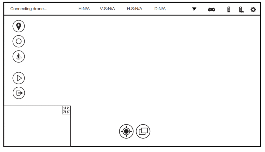
Switch between Footage & Map
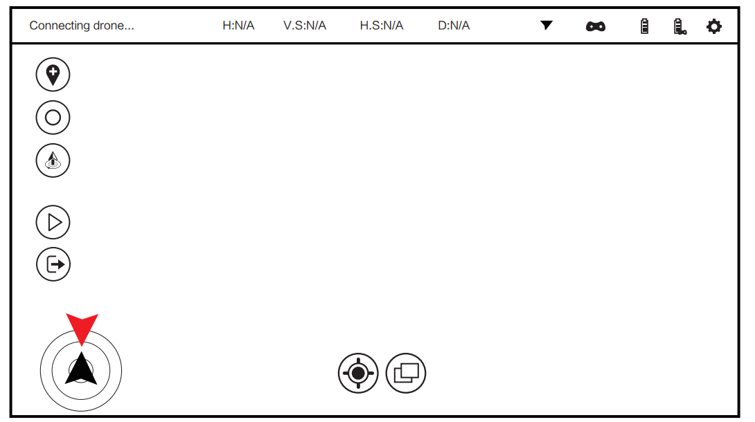
Tap the footage on the left bottom corner on the screen. The display will switch to the main screen and the map will shrink. Tap the map again, the display will switch to the main screen.Tap the icon [ ], the footage or map will become an icon [ ] , which shows the direction of aircraft’s nose and camera lens. Tap [ ] again, it will become footage or map again.
Adding Waypoints
- STEP 1) Press the icon [ ], the waypoint setting column will appear.
- STEP 2) Press the icon [ ] in the setting column and it will turn green, which means it is chosen successfully.
- STEP 3) Draw a route on the map. Pointing Tap the icon [ ]on the ST16 screen directly to add waypoints. Inserting Press and hold any point to insert or edit a waypoint. The waypoint properties may be edited.
Operating Waypoint Function
- STEP 1) Press and hold the Start/Stop button to start the motors.
- STEP 2) Press the [ ] icon and then slide the pop-up sliding block. The H920 PLUS will automatically fly along the mission route as pre-set. Press the [ ] and slide thesliding block; flight will be paused.
Operation for a Single-Waypoint Mission
After the mission route is set using the map, the system will automatically display several mission waypoints. Press any waypoint on the mission, or any figure on the top left of the screen. The mission may be configured for a single waypoint.
Settings for a single waypoint
- Relative altitude (minimum altitude is 16.4 ft./5m, default altitude is 65.6 ft./ 20m)
- Speed (range from .9KhH/0.06 mph to 30KmH/18.6 mph, default speed is 14.3KmH/8.9 mph)
- Settings for Gimbal Control in Pan and Tilt Directions
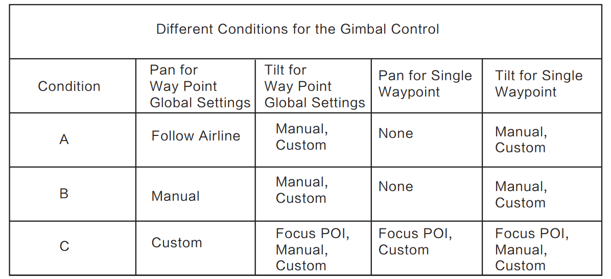
Pan
- Follow Airline: The pan direction of the gimbal will follow airline/mission line. It will move per the direction of the H920 PLUS nose.
- Manual: Switch S2 controls Pan Mode of the gimbal and Knob K1 controls Pan direction of the gimbal.
- Custom: In global setting, when pan mode is in custom, it will offer two choices in single waypoint pan mode.
- Custom value in pan direction: The value shows the angle that gimbal points to the north in pan direction. When the value shows 0°, it means the gimbal pan direction points to the north.
Tilt
- Point to the POI (only when the Custom Waypoint gimbal pan mode is selected in Global Settings): The gimbal will tilt and automatically point the camera lens to the POI.
- Manual: The operation identical to the gimbal tilt control in angle mode. The left slider on the ST16 controls gimbal tilt angle. The control range operates from 0° to -90°.
- Custom: At each waypoint, the tilt angle ranges from 90° to 0°. The custom angle will record the last angle setting.
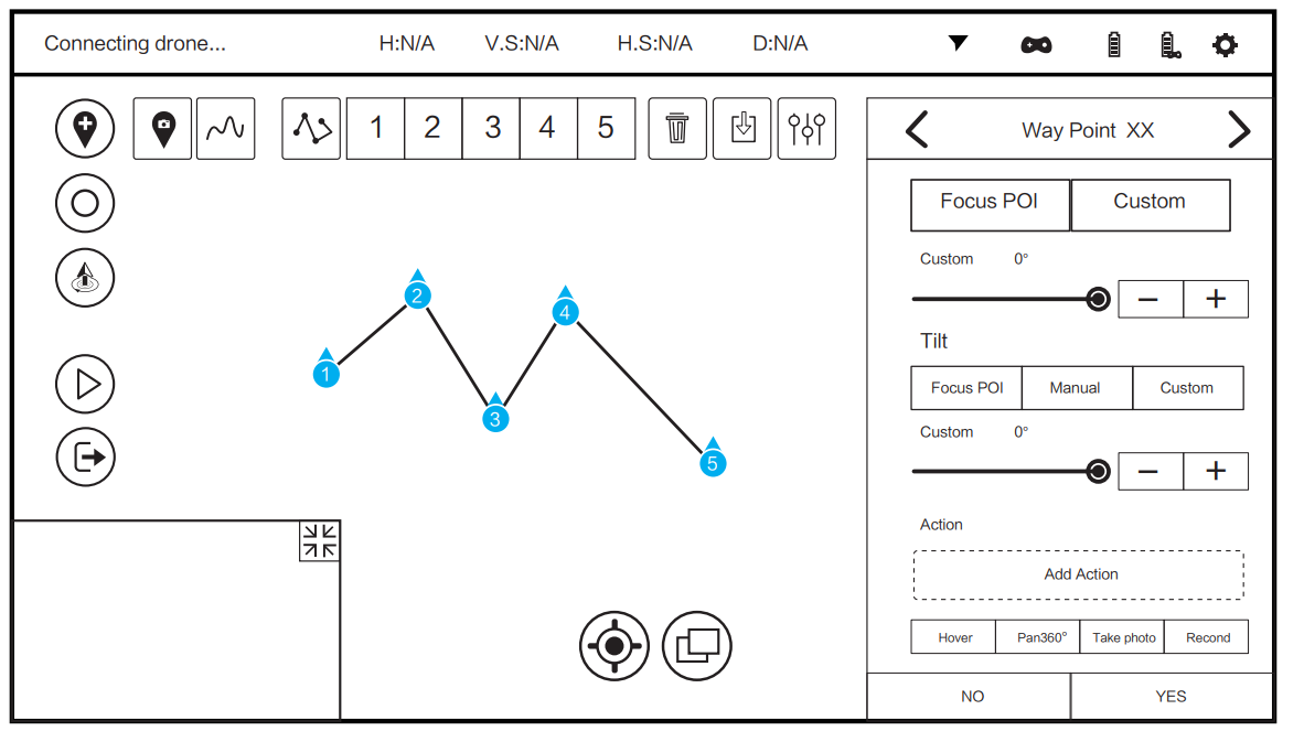
Adding Waypoint Actions
- STEP 1) Select any action below ” Add Action “. The selected action will display in blue.
- STEP 2) Press “Add Action” in the blue frame, and the added action will appear in the Action column.
- STEP 3) After all settings are completed, choose “YES.” Settings will be saved.
Point of Interest (Poi)
Multiple points of interest may be set before launching the H920 PLUS. Thegimbal/camera lens will point to the POI. If a waypoint is set to focus on a different POI, the previous setting will be applied to the POI. Press [ ] and then tap the display screen to set the POI. Tap the setting menu and the display will show as indicated below: Tap the delete icon [ ] and the POI will be deleted. Relative altitude: Set the altitude of the POI.
Mission/route-Planning Record
If any saved mission is to be recalled, press the icon | 1] and select the desired mission. The mission/route will show on the map.
Operation for All Waypoints
To simultaneously control and set parameters all waypoints, press | (B)] to set up for waypoints.
- Airline Type: Straight, Curve
- Relative altitude (minimum altitude is 16.4 feet; default altitude is 65.6 feet)
- Speed (range from 0.06 mph to 18.6 mph, default speed is 8.9 mph)
- Settings for pan and tilt directions of the gimbal on the waypoint:
Global Settings
- Global setting for pan and tilt mode before adding waypoints: Both pan and tilt modes of all single waypoints will change to global pan and tilt modes per global setting.
- Global setting for pan mode: pan modes of all single waypoints will change to global pan modes per global setting.
- Global setting for tilt mode: Any global setting for tilt mode will only affect the waypoints added after the setting. The pilot can set for single waypoint to make trim adjustment after the global setting.
Geo-Fence Function
The geo-fence is a user-determined, virtual barrier that will keep the aircraft flying within a selected area. If inertia causes the H920 to fly beyond the geo-fence, it will automatically return to a point within the fence area. The Geo-fence may be enabled
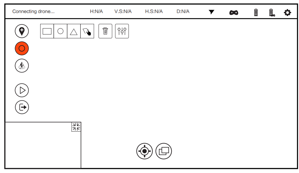
Select the fence icon [ ], and the task setting column will appear. There are square, circle and triangle fences by default. Select a shape, tap the screen, and a geo-fence of corresponding shape will display on the map. Tap the screen at the center of the desired geo-fence. Press and hold the central blue point indicator, and the entire fence may be moved. Slide the right sliding block, and the proportion of the fence may be changed. Select the [ ] icon and a custom-shape geo-fence may be set. Touch all desired on the map, and the system will automatically link them to form the geo-fence.\
Takeoff/point-To-Land
Press and hold the start/stop button until the propellers begin to spin. Press the [ ] icon and slide the sliding block. The aircraft will climb to the altitude of 5m/16.4 feet and hover/loiter. The [ ] icon will become a Point-to-Land [ ] icon. Select and tap on the screen at the desired landing point.
LED Status Indication
The Aircraft is in “Bind”Mode Blinks orange very rapidly (10 times per second) Initialization failed Pulses red (3 times per second) The Aircraft is in a No-Fly Zone *Flashes red and white rapidly (5 times per second) Please see the instruction manual for more information regarding no-fly zone
- The Aircraft is in Angle Mode without GPS lock Blinks purple (3 times per second) then off (for 1 second)
- The Aircraft is in Angle Mode with GPS lock Glows solid purple
- The Aircraft is in Home Mode Blinks red rapidly (5 times per second)
- Second Level low Voltage Battery Warning Flashes red,green and blue continuously
- ST16 with GPS lock blinks white every three seconds
- The Aircraft is in Smart Mode without GPS lock. It blinks green (3 times per second) then off (for 1 second)
- The Aircraft is in Smart Mode with GPS lock Glows solid green
- First Level low Voltage Battery Warning flashes red, green and blue every 3 seconds
- GPS DisabledFlashes purple(1 flash per second)
- Enter Task function Blink green and purple slowly (1 time per second)


Calibration Modes
- Compass Calibration Mode Entered. Blinks red and green slowly (2 times per second)
- Compass Calibration Started Blinks red and green rapidly (5 times per second)
- Accelerometer Calibration Mode Entered Blinks red, green and blue slowly(1 time per second)
- Accelerometer Calibration Mode Started Blinks red, green and blue rapidly (3 times per second)
- Calibration failed. Glows solid white
Preparing to Fly
Never attempt to operate H920 PLUS near tall buildings/obstructions that do not offer a clear view of the sky (a minimum clearance of 33m/100’). Be sure to place the H920 PLUS on a level and stable surface before powering ON the ST16 Ground Station and the H920 PLUS Aircraft.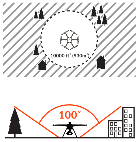
Step back approximately 26 ft (8 m) behind the H920 Plus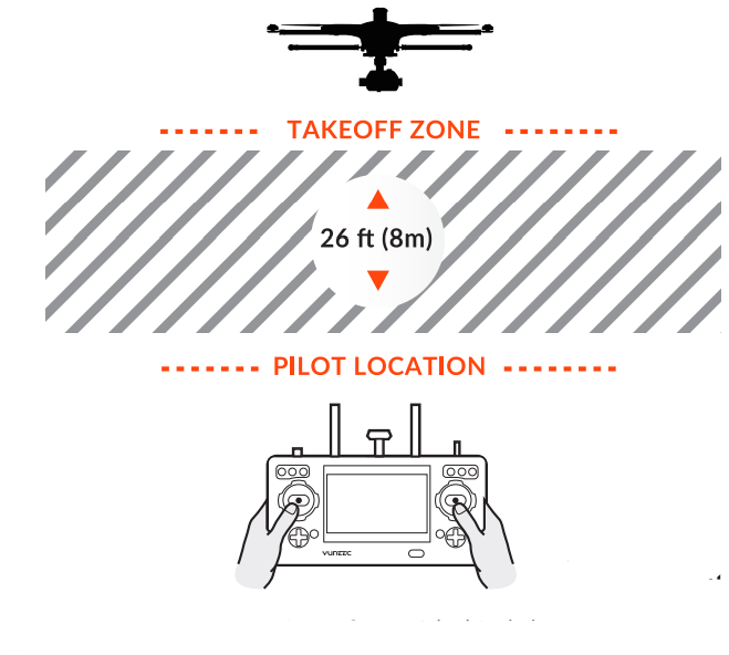
Compass Calibration

- STEP 1) Power on the ST16 Ground Station first and then the aircraft, and make sure they are connected correctly. If they are not connected correctly, the telemetry data will not display on the screen.
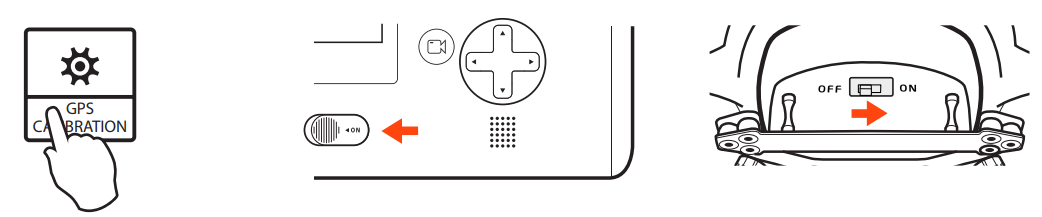
- STEP 2) Tap the GPS CALIBRATION icon on the ST16 screen and choose COMPASS.
GPS CALIBRATION - STEP 3) For best results, remove propellers if installed. Lift H920 PLUS airframe straight and level.
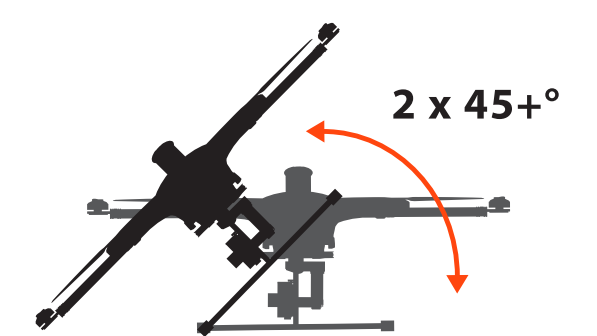
- STEP 4) Turn the aircraft 60° to the left and then turn it forward as shown by the red arrow above until you hear three beeps.
- STEP 5) Turn the aircraft 60° to the left again and then turn it forward as shown by the red arrow above until you hear four beeps
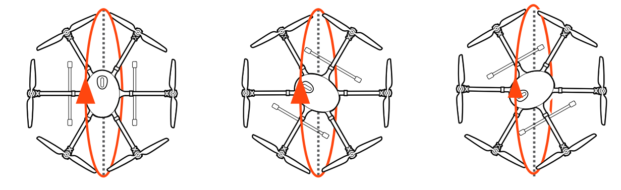
- STEP 6) Turn the aircraft 60° to the left again and then turn it forward as shown by the red arrow above until you hear five beeps.
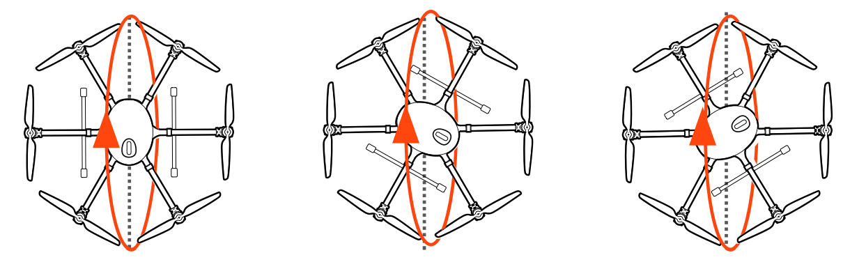
- STEP 7) Turn the aircraft 60° to the left again and then turn it forward as shown by the red arrow above until you hear six beeps.
- STEP 8) Turn the aircraft 60° to the left again and then turn it forward as shown by the red arrow above until you hear the acknowledgement tone.
Binding
- STEP 1) Power on the ST 16 Ground Station and power on the H920 PLUS aircraft.
- STEP 2) The H920 PLUS toward the nose twice until the Main LED indicator blinks orange rapidly.
- STEP 3) On the ST16, open the system settings menu and tap the ‘Refresh’ button.
- STEP 4) Select the ‘SR24_XXXXX’ receiver listed in the column under ‘Model’, and YUNXXXXX Wi-Fi listed in the column under ‘camera’ on the ST16 Ground Station. Select ‘Bind’ and then enter the password ‘1234567890’ to connect to Wi-Fi. Select CGO4 to complete the camera binding process.
- STEP 5) Tap the ‘Back’ button to return to the main screen, and two long beeps confirm the connection. The camera video will display on the ST16 screen.
Camera Controls
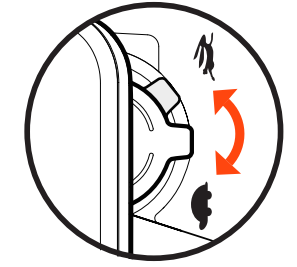
There is a gimbal tilt mode switch on ST16 labelled “S1.” When the switch is in the up/middle position, the CGO4 (or other gimbal system) gimbal camera is in Angle Mode. Use the slider (C) on the under-left side of the ST16 to set the tilt position of the gimbal camera. The distance between the slider(C) and the middle position determines the tilt speed; the further the distance, the faster the tilt speed.
- Button A = Take Still Photo
- Button B = Start/Stop Recording Video
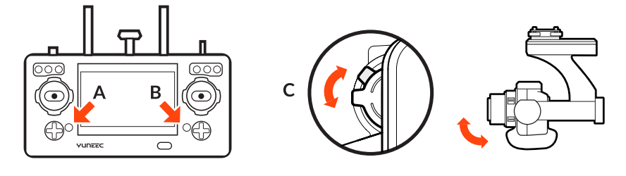
The gimbal pan mode switch on ST16 (S2) enables the Follow Mode. When the switch position is UP, the gimbal camera is in Follow Mode. The pan control of the gimbal camera is disabled when the switch position is UP. The gimbal camera will adjust its pan direction per the aircraft’s movements. When the switch is in the middle position, the gimbal camera is in Follow Pan Controllable Mode, and the gimbal camera will adjust its pan direction per the aircraft’s movements. Use the Pan Control Knob to set the pan position of the gimbal camera. When the switch position is down, the gimbal camera is in Global Mode. The pan direction of the gimbal camera will be fixed regardless of the aircraft’s movements. Use the Pan Control Knob to set the pan position of the gimbal camera.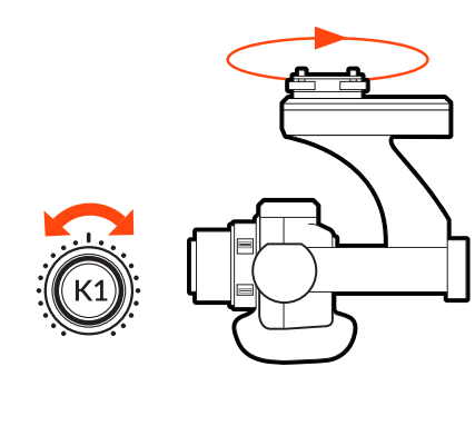
FCC Statement
This equipment generates, uses, and can radiate radio frequency energy and, if not installed and used in accordance with the instructions, may cause harmful interference to radio communications. However, there is no guarantee that interference will not occur in a particular installation.
- Increase the separation between the equipment and receiver.
- Consult the dealer or an experienced radio/TV technician for help. This device complies with part 15 of the FCC rules. Operation is subject to the following two conditions: This device may not cause harmful interference, and (2) this device must accept interferencereceivedd, including interference that may cause undesired operation.
RF Exposure Warning
This equipment must be installed and operated in accordance with the provided instructions, and the antenna(s) used for this transmitter must be installed to provide a separation distance of at least 20 cm from all persons and must not be co-located or operating in conjunction with any other antenna or transmitter. End-users and installers must be provided with antenna installation instructions and transmitter operating conditions to satisfy RF exposure compliance.
IC Radiation Exposure Statement for Canada
This device complies with Industry Canada license-exempt RSS standard (s). Operation is subject to the following two conditions:
- This device may not cause interference, and
- This device must accept any interference, including interference that may cause undesired operation of the device.
EU Compliance Statement
Hereby, Yuneec International (China) Co., Ltd. declares that this device is in compliance with the essential requirements and other relevant provisions of the RED Directive 2014/53/EU. The full text of the EU Declaration of Conformity is available at the following internet address: http://yuneec/de-downloads. Please visit the address above and enter the corresponding product page.
Customer Service
- Website: www.yuneec.com.
- Telephone: 0208 449 4321