


Digital Projection 8K Series Digital Projector
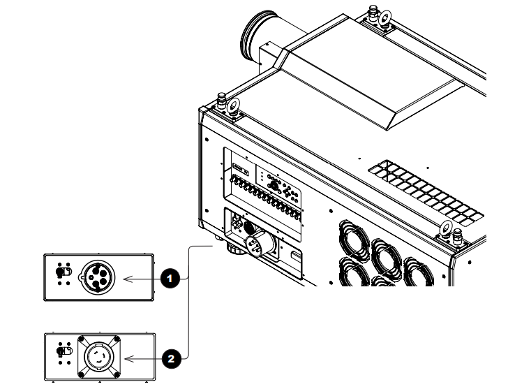
Connecting The Power Supply
Rest of the world:
- Firmly push the mains connector into the socket. USA only:
- Firmly push the mains connector into the socket. Rotate the connector 20° clockwise to lock it in place.
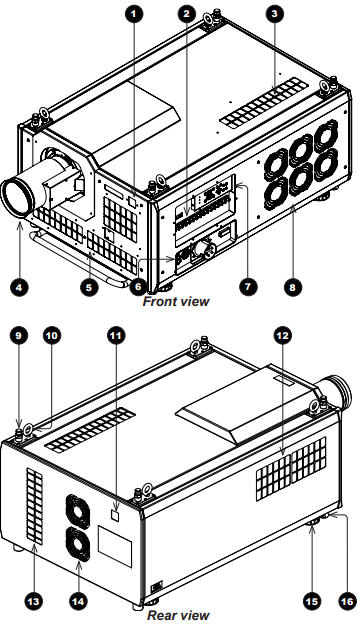
Projector Overview
Front and rear views
- Front IR window
- Inputs
- Air inlet: An identical air inlet is located at the bottom of the projector, right below this one.
- Lens
- Air inlets
- Mains plug with switch and voltage meter
- Keypad
- Air outlet
- Top stacking point. There are four top stacking points: one in each corner.
- Lifting ring. There are four lifting rings: one in each corner.
- Rear IR window
- Air inlet
- Air inlet
- Air outlet
- Adjustable foot. There are four adjustable feet: one in each corner.
- Bottom stacking point. There are four bottom stacking points: one in each corner.
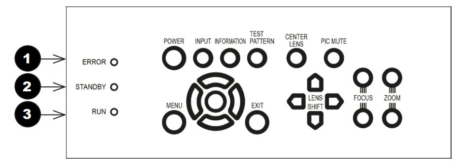
Keypad Instructions
- POWER Switches the projector on and off (STANDBY).
- INPUT Switches to the next input source.
- INFORMATION Displays.
- CENTER LENS Centres the lens.
- PIC MUTE Switches the laser off/on.
- MENU Displays and exits the OSD.
- Arrow buttons & ENTER Navigation buttons used to highlight menu entries in the OSD.
- EXIT Exits the current OSD page and enters the level above.
- LENS SHIFT arrow buttons. Each of these buttons moves the lens in the specified direction. The
- FOCUS plus and minus buttons are used to move the focus in and out.
- The Zoom plus and minus buttons are used to zoom in and out.
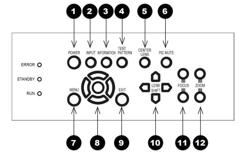
Keypad Indicators
- ERROR A red indicator that shows the following patterns: Off = No Error, single flash followed by a pause = Lamp abnormality, double flash followed by a pause = Uncovered lamp cover, triple flash followed by a pause = Abnormality, four flashes followed by a pause = Overheat, continuous light = System abnormality
- STANDBY: A green indicator that shows a continuous light when standby mode is activated
- RUN A blue indicator that shows the following patterns: Off = Power is off,f Flashing = Projector is cooling down during power off, or warming up during power on. A continuous light = Power is on
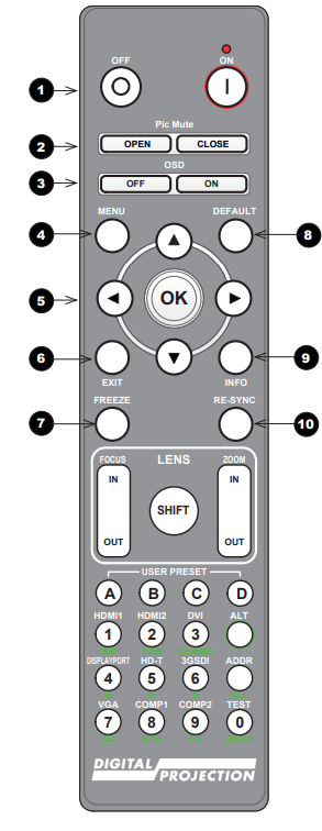
Remote Control
- Power ON/OFF Turns the projector on and off.
- To turn the projector off, press the OFF button twice within five seconds.
- Pic Mute OPEN / CLOSEShows and hides the projected image.
- OSD ON / Enables and disables screen timeout messages and shows the OSD during projection.
- MENU Access the projector OSD (on-screen display).
- EXIT: Close the current OSD page and return to the level above.
- FREEZE Freeze the current frame.
- DEFAULT: Restore default settings.
- INFO Access information about the projector.
- RE-SYNC Re-synchronise with the current input signal

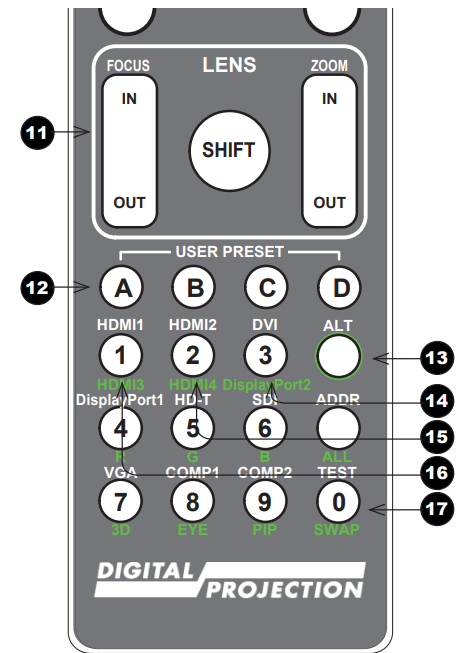
- LENS adjustment FOCUS IN / OUT: adjust focus. SHIFT: press and hold this button, then use the Navigation arrow buttons to move the lens. ZOOM IN / OUT: adjust zoom.
- USER PRESET A, B, C, D Load user presets.
- ALT Press and hold this button to access alternative functions for all buttons with a green label.
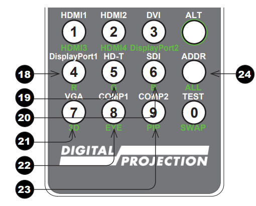
- DVI / DisplayPort2 / numeric input.
- HDMI 2 / HDMI 4 / numeric input. 2.
- HDMI 1 / HDMI 3 / numeriinputput 1.
- TEST / SWAP / numeric in0: Show a test pattern.

- DisplayPort1 /R/ numeric input 4.
- HD-T /G/ numeric input 5 There is no HDBaseT input on this projector.
- SDI /B/ numeric input .6 There is no SDI input on this projector.
- VGA /3D/ numeric input. 7 There is no VGA input on this projector.
- COMP1 /EYE/ numeric input 8 There is no COMP1 input on this projector.
- COMP2 /PIP/ numeric input 9 There is no COMP2 input on this projector.
- ADDR / ALL Assign and unassign an IR remote address. To assign an address

Positioning The Screen And Projector
- Install the screen, ensuring that it is in the best position for viewing by your audience.
- Mount the projector, ensuring that it is at a suitable distance from the screen for the image to fill the screen. Set the adjustable feet so that the projector is level and perpendicular to the screen.
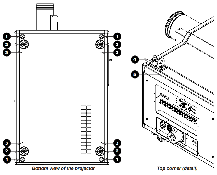
The drawings below show the feet for table mounting and the fixing holes for ceiling mounting. Also shown is one of four rings, each located in the top corners. These can be used for lifting a single projector.
- Four stacking points
- Four adjustable feet
- Four M10 holes for ceiling mount. The screws should not penetrate more than 18 mm into the body of the projector.
- Stacking point at the top of the projector
- Lifting ring (for handling a single projector). The rings can be removed to reveal M10 x 18 deep holes for ceiling mounting.
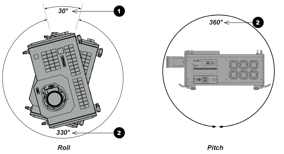
Tilt
The projector can be operated in numerous positions. It is recommended to position the projector in portrait mode with inputs facing upward, as shown in the diagram.
Operating The Projector
Switching the projector on
- Connect the power cable between the mains supply and socket 1.
- Switch on at the ON/OFF switch 2.
- Press ON on the remote control or the control panel to switch the projector ON.
- The run indicator on the control panel will flash blue until the projector has warmed up.
- The light source will light, and the shutter will open.
- The run indicator will show a continuous blue light, and the standby indicator will show green when the projector has warmed up.
Switching the projector off
- Press OFF twice on the remote control or the keypad. The run indicator on the control panel will flash blue until the projector has cooled down.
- The cooling fans will run for a short time until the projector enters STANDBY mode. The run indicator will show a continuous blue light, and the standby indicator will show green when the projector has cooled down.
- If you need to switch the projector off completely, switch off at the mains power switch next to the power connector and then disconnect the power cable from the projector.
Selecting an Input Signal
The last selected input remains active until a new input is selected. To select a new input:
- Connect either a 3G-SDI or 12GSDI image source to the projector. Refer to the “Connection Guide”
Select the appropriate resolution:
- Press MENU to open the On-screen display (OSD).
- Use the UP and DOWN arrow buttons to highlight Input from the main menu and press ENTER/OK.
- Use the UP and DOWN arrow buttons to highlight Format from the input menu and press ENTER/OK.
- Use the UP and DOWN arrow buttons to highlight a setting. Choose from Auto, 8K, 4K, or HD. Press ENTER/OK to confirm your choice.
Adjusting the lens
The lens can be adjusted using the lens buttons on the keypad or remote control. On either device, press FOCUS, ZO, O, M, or SHIFT, then use the arrow keys to adjust the lens. Adjusting the image Orientation
Set the orientation setting from the OSD menu:
- Press MENU to open the On-screen display (OSD).
- Use the UP and DOWN arrow buttons to highlight Setup from the main menu and press ENTER/OK.
- Use the UP and DOWN arrow buttons to highlight Projection Mode from the setup menu and press ENTER/OK.
- Use the UP and DOWN arrow buttons to highlight a setting. Choose from Front Desktop, Front Ceiling,\ Rear Desktop, or Rear Ceiling. Press ENTER/OK to confirm your choice.
Picture
Settings such as Gamma, Brightness, and Contrast can be set from the Image menu.
- Press MENU to open the On-screen display (OSD).
- Use the UP and DOWN arrow buttons to highlight Image from the main menu and press ENTER/OK.
- Use the UP and DOWN arrow buttons to highlight a setting. Press ENTER/OK to access the settings menu or use the RIGHT and LEFT arrow buttons to adjust a setting.
Essential Maintenance
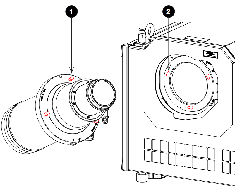
Fitting the lens
- Insert the lens into the mount. Engage the three locating studs 1 into the corresponding slots 2 on the mount.

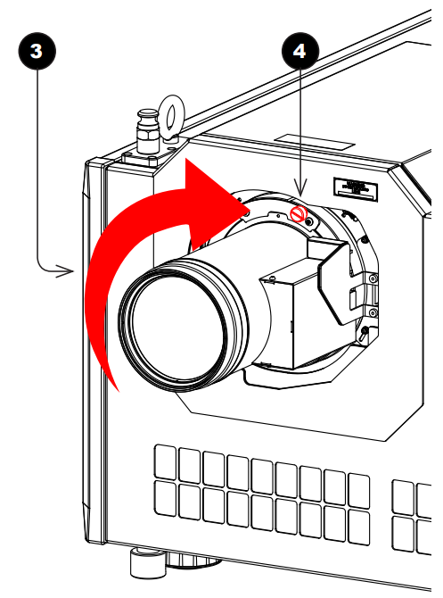
- Rotate the lens clockwisetimes 3 until the studs slide all the way into the slots.
- Tighten the two fixing screws 4 on the collar.r

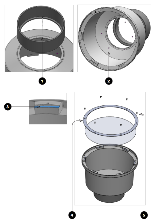
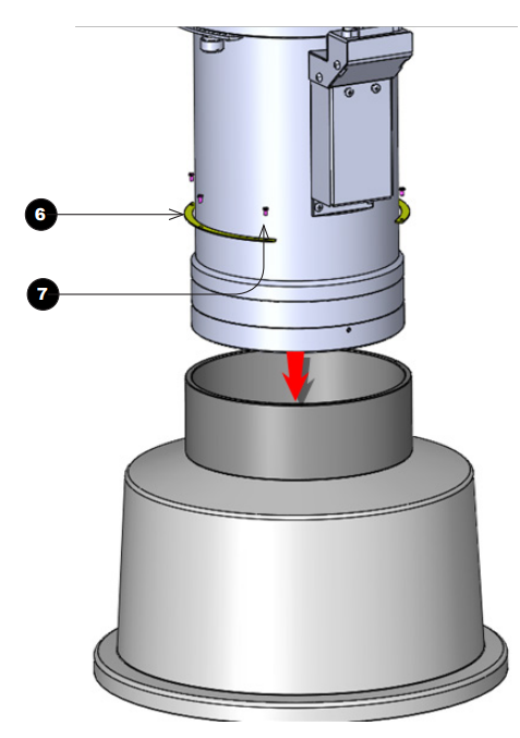
Fitting a lens hood
A lens hood must be fitted to the lens (P/N 115-632) for use in the USA.
- Place the adaptor ring on the rear of the lens case.
- Use the guide pin to ensure it is located correctly.
- Insert and tighten the six fixing screws 2 to secure the adaptor ring to the lens case.
- Place the glass lens over the lens case.
- Ensure the glass is located correctly.
- Place the plate over the glass lens. 4
- Insert and tighten the six fixing screws 5 to secure the plate and glass lens to the lens case.

- Insert the lens into the adaptor ring.
- Ssh-fit the lens until the plate ring is located against the adapter ring.
- Insert and tighten the six fixing screws 7 to secure the lens and the lens hood.

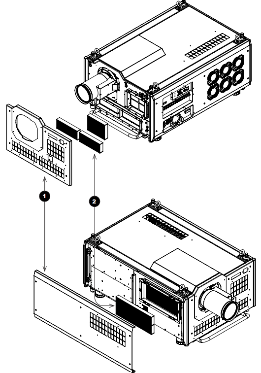
Replacing the filters
- Loosen the six captive screws, then remove the front/side panel 1.
- Replace the filters 2.
- Reattach the panel and tighten the screws.
Customer Service
- Website: https://www.digitalprojection.com/
- Tel: 44 (0) 161 947 3353