


CHRISTIE D4K2560 High Frame 4K Projector
Introduction
This manual is intended for professionally trained operators of Christie high-brightness projection systems. These operators are qualified to replace the lamp and air filters, but should not attempt to install or service the projector. Only Christie technicians who are knowledgeable about the hazards associated with high-voltage, ultraviolet exposure, and the high temperatures generated by the projector lamp are authorized to assemble, install, and service the projector.
Safety Instructions
This project must be operated in an environment that meets the operating range specification. Use only the attattachments/ or accessories recommended by Christie.
- For protection from ultraviolet radiation, keep all projector housings intact during operation.
- Protective safety gear and safety goggles are recommended when servicing.
- Position all cables where they cannot contact hot surfaces or be pulled or tripped over.
- Be aware that some medications are known to increase sensitivity to UV radiation.
- Optical adjustments are not considered maintenance.
- The lamps are turned on during optical adjustments, and emissions are present.
- The projector uses a high-pressure lamp that may explode if it’s not properly handled.
- A qualified technician is required for all installations.
- Use of the projector’s rear safety strap is mandatory to prevent the projector from tipping.
- Secure the strap between the projector and the surface it is mounted to.
- Do not overload power outlets and extension cords, as this can result in fire or shock hazards.
Projector overview
The D4K2560 is a professional-quality, easy-to-use, split-body projector using Digital Light Processing ( DLP™) technology from Texas Instruments. I ntegrating sm oothly into traditional projection environments, the D4K2560 interfaces with local networks throughout the world, for multimedia presentations from a variety of formats to offer stunning, wide-screen, high-resolution 4K images at 60 frames per second.
Key features
- 3-chip 4K DLP™ light engine
- 4096 x 2160 native pixel format
- 2.0 and 3.0 kW Xenon lamps available
- Warp and blend of projected images
- Supports screens up to approximately 100 feet in width
- Touch panel controller (TPC) for the matrix in the projector interface.
- 1x 10/ 100BaseT Ethernet port
- RS232 ports for communication
- 4x Option slots accepting a variety of digital video input option cards
- LiteLOC™ feature for constant image brightness
- Lam pLOC™ feature for motorized three-axis lamp alignment
- Electronically operated “quick” douser
- Motorized lens mount
- LED indicators on the rear corners of the projector for easy-to-read status indication
- Replaceable air filters (no tools required)
- Optional rack m ount stand
- Choice of field-interchangeable zoom lenses

How the Projector Works
The D4K2560 accepts a variety of input signals for projection on front or rear projection screens, typical in commercial or other large screen applications. High-brightness light is generated by a short arc Xenon lamp, then modulated by three Digital Micromirror Device (DMD) panels responding to incoming data streams of digitized red, green, and blue color information. As these digital streams flow from the source, light from the responding “on” pixels of each panel is reflected, converged, and then projected to the screen through one or more projection lenses, where all pixel reflections are superimposed in sharp full-color images.
List of components
Verify the following components were received with the projector:
- Touch panel controller (TPC)
- Lens plug
- Light engine removal tool
- Convergence tool
- Nylon safety strap with a clip
- Warranty card
- Shroud
- Access keys
- Web registration form
Installation and Setup
This section explains how to install, connect, and optimize the projector display. To safely install and operate the project, the installation on location must have restricted access for authorized personnel only and meet these minimum requirements.
Physical operating environment
- Maximum Ambient Temperature (operating) 35° C (95° F)
- Minimum Ambient Temperature (operating) 10° C (50° F)
Power Connection
The requirements listed below are applicable for permanent wired installation or power cord connection:
- Term inal block, electrician hard-wired to the projector head.
- Electrical rating: 200 – 240 VAC, 23 A max.
- This product can be connected to an ITpower distribution system.
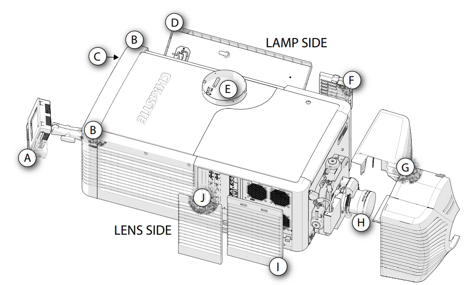
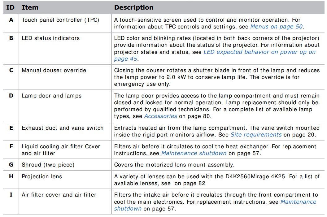
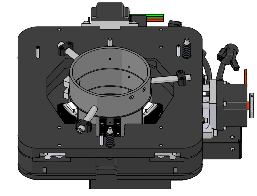
Projector Components
Position the Projector
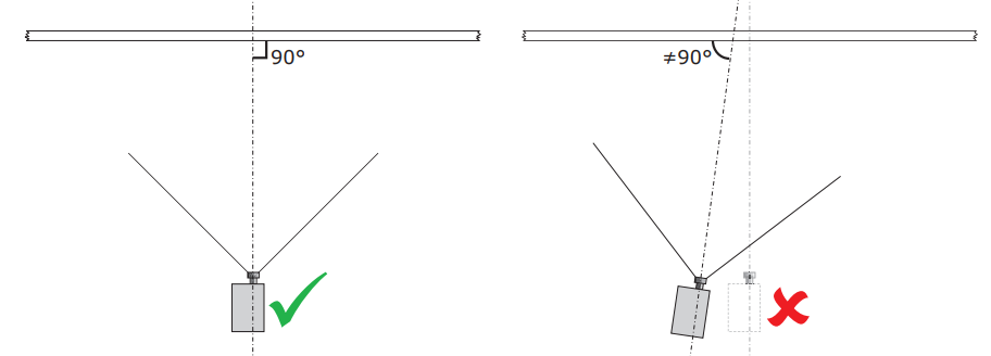
Keep the projector lens as perpendicular to the screen as possible, even if significantly above the screen center. When a particularly short throw distance combines with a wide screen, you may have to forfeit some aim and stay more perpendicular to the screen. In such cases, some lens offset can reduce the keystone distortion.
- Position the projector at an appropriate throw distance (projector-to-screen distance) and vertical position.

- If using an optional rack stand (P/ N: 108-282101-02), assemble the rack stand using the instructions provided with the rack stand.
Connect to AC power
Failure to comply with the following could result in death or serious injury.
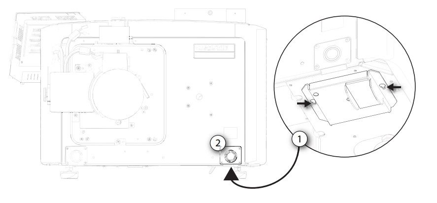
- Remove four screws securing the knockout plate to the bottom right corner of the front bezel.
- Remove the knockout plate. The AC supply is routed to the terminal block through an appropriate strain relief mounted on this knockout plate.

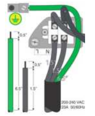
- Connect to the term inal block. The terminal block accommodates up to an eight AWG wire. If required, use a 90° strain relief connector to route the power cable in a downward direction. Always connect the ground lead first to reduce the shock hazard.

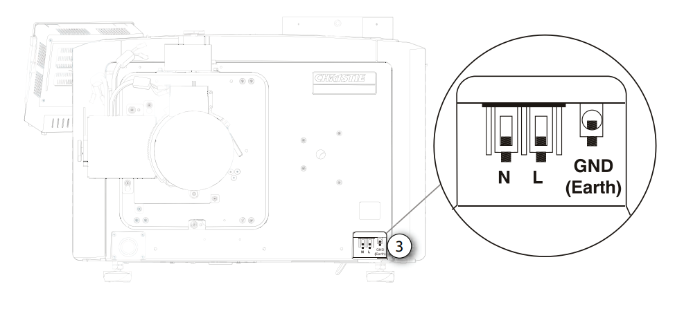
- If connecting to permanent power, connect the AC power source to the terminal block, beginning with the ground lead.
- If connecting to a pluggable type-B cable, connect the cable to the terminal block, beginning with the ground lead.

- Reinstall the knockout plate and secure it with four screws.
- Reinstall the bottom access panel over the term inal block and secure it with two screws.
- If using a pluggable type-B cable, connect to the building’s AC power source.
Adjust the Projector Tilt and Level
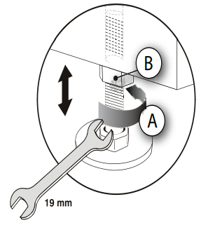
- Secure a safety lifting strap rated to handle the projector’s weight at the rear of the projector. Hoist up the projector. To adjust the vertical or horizontal position of the projector, extend or retract the adjustable feet on the bottom of the projector (A).
- Once the required adjustment is made, tighten the lock nut against the bottom of the projector (B). The projector provides 4 inches of adjustment at the front and 11.5 inches of adjustment at the rear.
- If the vertical or horizontal position of the projector requires more adjustment than the standard feet allow, two 6-inch extension rods can be installed to increase the amount of available adjustment.t

Foot Extension Rods
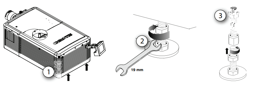
- Elevate the rear of the projector to access the two rear feet.
- Remove the feet by loosening the lock nut and rotating each foot out of the projector.
- Add the extension rods to the standard feet.
- Thread the extended feet into the projector’s baseplate.
- Adjust the feet until the required tilt is achieved.
- Lock the feet in place by turning each lock nut until it fits tightly against the projector.
Touch Panel Controller
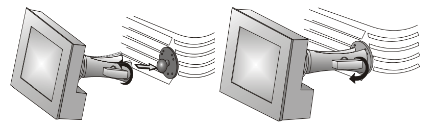
- Loosen the mounting arm just enough for the end to fit over the ball joint located on the rear panel of the projector.
- The touch panel controller (TPC) becomes loose from the mounting arm when the mounting arm lock is loosened.
- Tighten the mounting armlock until it fits tightly on the joint. The TPC safety strap comes installed on the projector ball point.
- Connect the cable from the touch panel controller (TPC) to the connector on the rear panel of the projector.
- Adjust the TPC angle for optimal viewing, then tighten the mounting arm lock securely so that the TPC is held in place at the required location.
Use t his form ula to determine the CFM value for the projector: 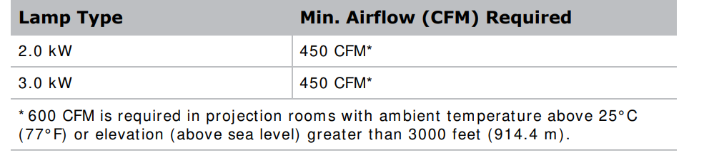 Add an extractor or a booster if there is insufficient airflow. Do notmount thee extractor on the projector as this may introduce some vibration into the image.
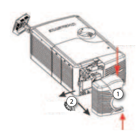
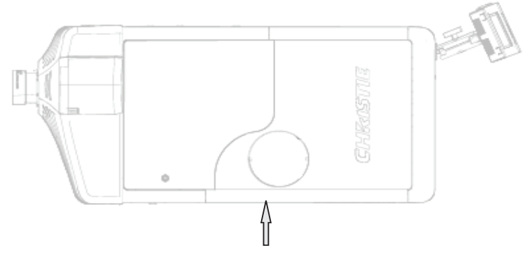
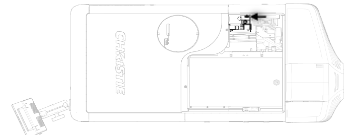
Remove the Projector Shroud
The lens side shroud must be removed to gain access to the lens. The other shroud must remove the connection of the AC power cord to the front face of the projector
- Use finger pressure to push down on the shroud clips located at the top and bottom of the shroud as shown by the arrows. Carefully slide the shroud sideways and forward away from the lens m mountnd lens.

- Place the shroud covers on a clean surface to prevent scratches
Set Up the Lens
- Remove the projector shroud.
- Make sure the lens locking lever is in the up position.
- I fIfached, remove the rear lens cap from the lens.
- Slide the lens into the lens mount, aligning all connections.
- 5. Secure the lens with the lens locking lever (down position).
- Calibrate the lens motors.
Portrait Mode
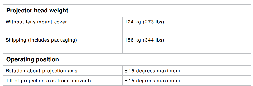
- Orient the projector in the frame with the lamp door facing downward (as shown). The maximum tilt angle is ± 15 degrees.

- Set up the customer-supplied mounting frame.
- Remove the projector feet.

- Perform a lamp alignment.
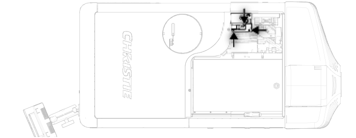
Connect Devices
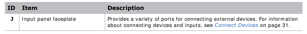
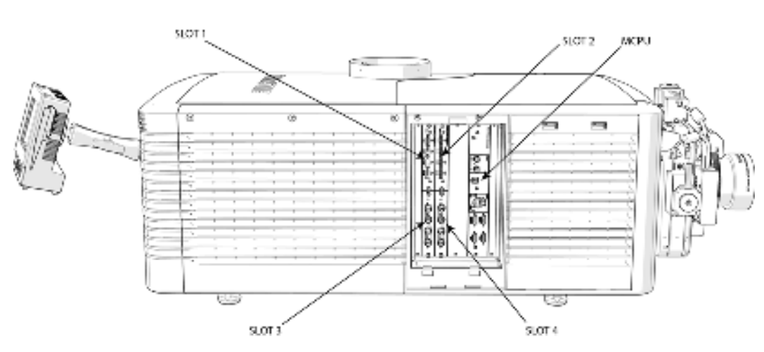
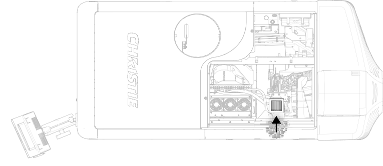
This section provides information and procedures for connecting external devices to the projector. Communication and input ports are located on the projector’s side input panel, accessed by removing the input panel cover. When connecting devices, you can route cables through the opening in the frame toe side input panel or directly to the video option cards and MCPU. The image below shows the video option card slot numbers and the MCPU panel. Input signal devices are connected to the video option cards, nd the option card slot numbers are important for some types of input signals. Communication devices are connected to the MCPU panel.
Input Video Mapping
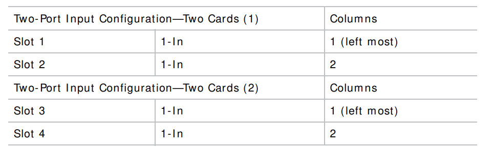
Video input mapping depends on the type of cards used for the Four- Port oTwo-Port inputtut configurations.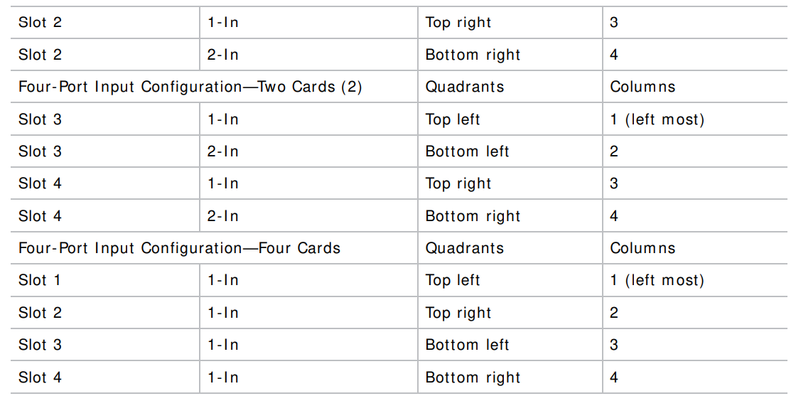
3GIC, TDPIC, THIC cards
The following table shows the video quadrant mappings for the 3GI C, TDPI C, and THI C Four- Port input configurations.
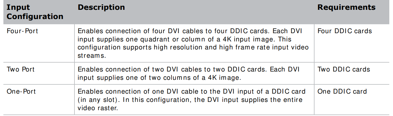
Four-Port: DDIC card
The following table shows the video quadrant mappings for the DDIC Four-Port input configuration: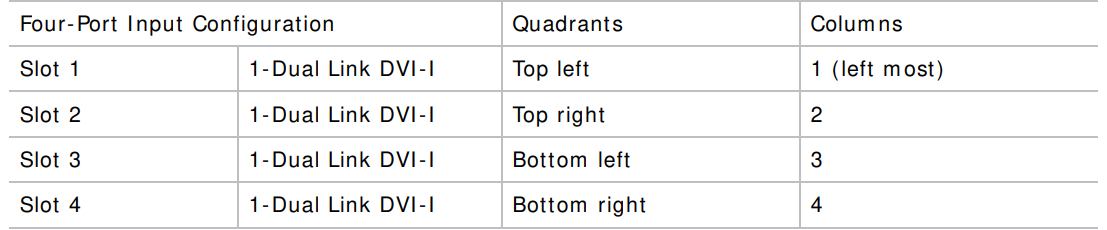
TDPIC card DDIC card
 Connect a Video Source Using Display Port
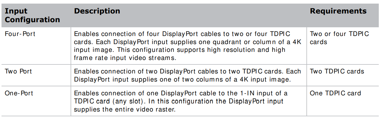
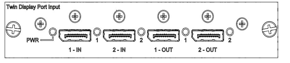
The Twin DisplayPort Inputcard ( TDPI C) accepts digital video data from the DisplayPort sources. The input configurations listed below are supported.
 3G Input Card
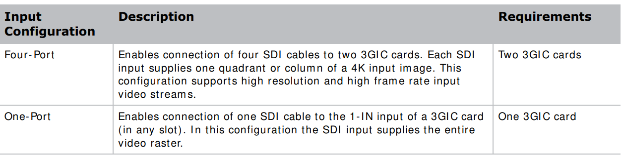
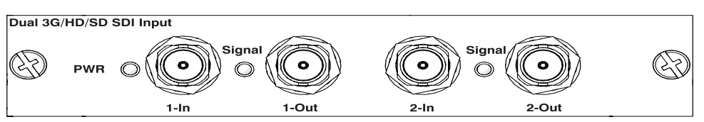
The 3G I nput card3GIC C) accepts digital video data from HD and 3G-SDI (Serial Digital Interface sources. The input configurations listed below are supported.
HDMI
The Twin HDMInputcard ( THI C) accepts digital video data from HDMI sources. The input configurations listed below are supported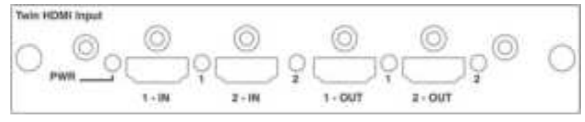
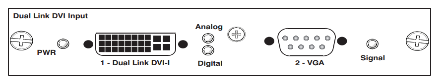
DVI
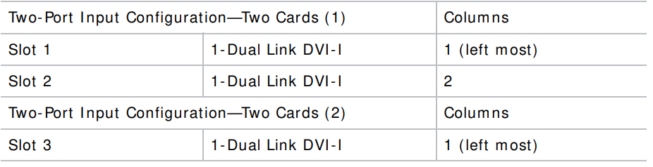
The Dual Link DVI Input card ( DDI C) accepts digital video data from DVI sources. It does not support incoming analog signals. The input configurations listed below are supported.
Select a Video Source
After connecting a video source to the projector, you must select it using the touch panel controller ( TPC)
- On the TPC, select Input > Channel. Scroll the list of channels until you find the channel that best matches your configuration.
- Tap the channel. An image appears on the screen. If an image does not appear on the screen, repeat steps 1 to 3 to select a different channel.
Computer & Server
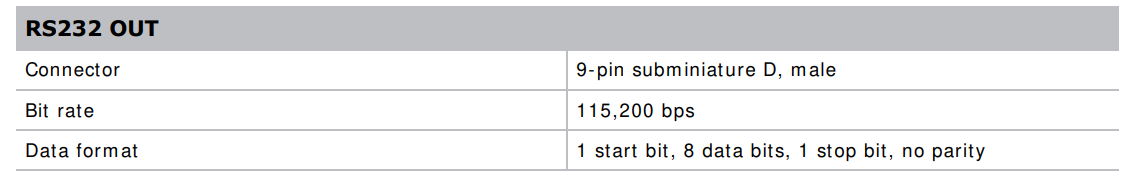
To communicate with a remote computer, server, or an existing network, use an RJ- 45 cable to connect the Ethernet hub or switch to the Ethernet port located on the projector MCPU faceplate. When using the Christie serial protocol over Ethernet, connect to port 3002. For applications or equipment using serial communications, use the Christi proprietary serial protocol to communicate with the RS422 port or the RS232 ports on the MCPU faceplate.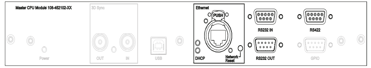
Set up the Ethernet
Ethernet is set up to obtain an IP address automatically if a DHCP server is on the network. To
Modify IP settings, or manually enter the address.
- On the touch panel controller, tap Menu > Configuration > Ethernet Settings > Modify IP Settings.
- Set the network information for the projector:
- To obtain information automatically from the network, tap Automatic.
- To manually enter the network information, tap Manual and enter the IP Address, Subnet Mask nd Gateway (optional).
Adjust the Image
This section provides information and procedures for adjusting the projector image. Select screen image orientation. The projector supports front projection, rear projection, front projection inverted, and rear projection inverted.
- On the touch panel controller, tap Menu > Configuration > Screen Image Orientation.
- Select the required orientation from the list.
Maximize Light Output
To ensure optimal operation, use LampLOC to adjust the lamp position whenever a new lam lampinstalled or changes in the projector orientation (for example /, to portrait mode).
- On the touch panel controller, tap Menu > Lamp > LampLOC.
- Tap Auto LampLOC.
Align the Image
This procedure ensures that the image reflected from the digital micromirror device (DMD) is parallel and centered with the lens and screen. Complete this procedure before adjusting boresight.
- Verify that the projector is properly located and positioned relative to the screen.
- Display a test pattern that can be used to analyze the focus and geometry.
- Perform a preliminary focus and (if available) a zoom adjustment with the primary lens installed. Always focus on the center of the image first.
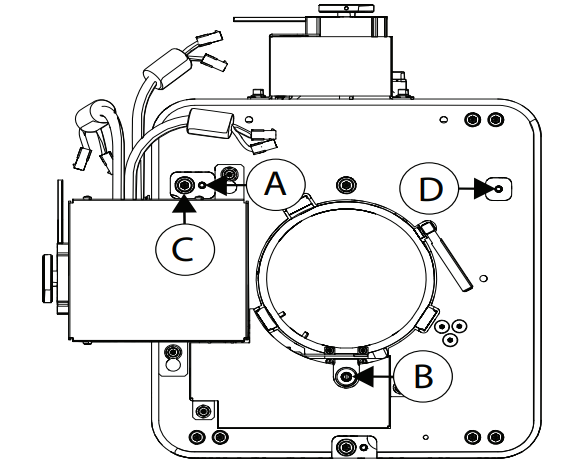
Offset
Project an image with the primary elements. Always adjust the offset before adjusting the borders in sight S. Select the framing test pattern and then adjust the vertical (A) and horizontal (B) offsets to display a square image on the screen, with minimal projector aiming error.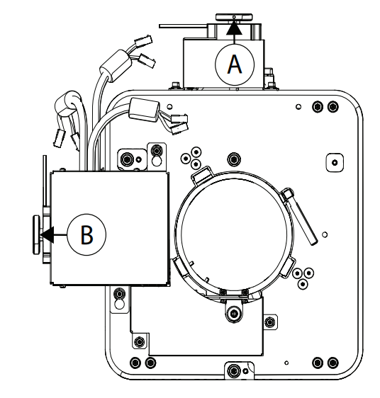
- Loosen the lens mount stabilization screw (D).

- Loosen the horizontal lock screw ( A)
- Extend the lens focus ( B) completely.
- Check the boresight again.
- Unless proceeding to adjust vertical boresight, perform a lens calibration.
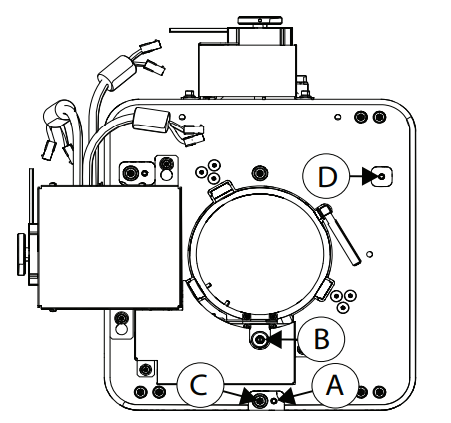
Vertical Boresight
- Focus the image at the top edge of the screen
- Loosen the lens mount stabilization screw (D).

- Loosen the vertical lock screw (A).
- Extend the lens focus (B) completely.
- Repeat Steps 2 to 5 until the top and bottom of the screen are both well-focused.
- Re-focus the center of the im age. The goal is for good focus at the center and on all sides.
- Tighten the lock screw (A) and the lens m ount stabilization screw (D) to maintain the adjustments.
- Check the boresight again. Perform a lens calibration.
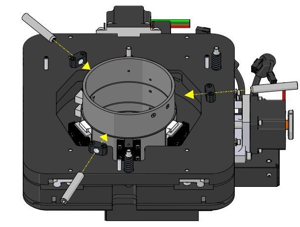
Lock the Lens Offsets
T..he lens locking feature reduces image vibration. For most applications, s locking is not necessary.
- Use the touch panel controller (TPC) or manually adjust the lens offsets to the required position.
- Unpack and install the three lens offset locking screws

- Tighten each locking screw until each screw contacts the lens offset collar.

- With equal pressure, tighten each locking screw against the lens offset collar.
- Disconnect the lens motor communication cable
DMD Convergence
A convergence problem occurs when one or more projected colors (red, green, blue) appears m isaligned when exam ined with a convergence test pattern. Norm ally, the three colors should overlap precisely to form pure white lines throughout the im age and one or m ore poorly converged individual colors m ay appear adjacent to som e or all of the lines. Contact your Christie accredited service technician to correct DMD convergence issues.
Color Correction
The D4K2560 provides predefined and custom color adjustments in the Color Correction menu. The available color adjustment controls are listed in the table below: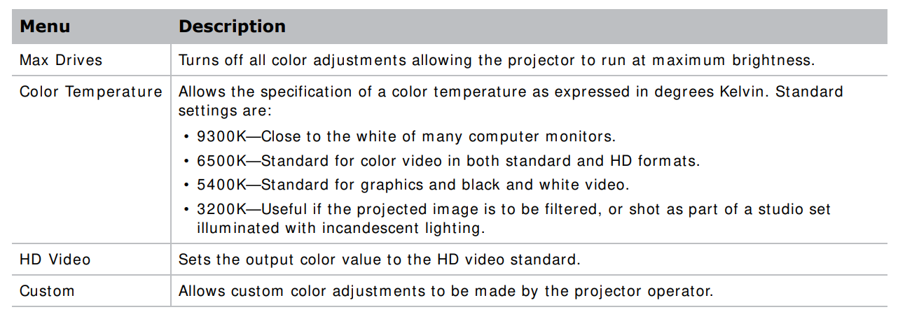
Adjust the color by Temperature.
Colour temperature adjusts the overall color gamut and does not allow for precise adjustments to specific primaries.
- On the touch panel controller, tap Menu > Configuration > Color Correction > Select Color Adjustment.
- From the list, select Color Temperature.
- Tap Color Temperature.
- Adjust the temperature value and tap OK.
- On the touch panel controller, tap Menu > Configuration > Color Correction > Select Color Adjustment.
- From the list, select Custom.
- Tap Color Adjustments by X, Y.
- Adjust the precise hues of each primary color component
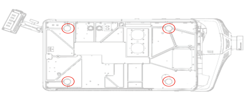
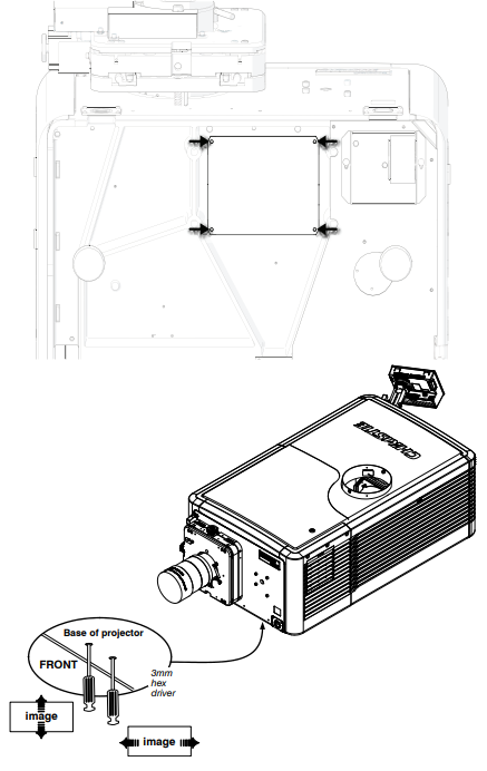
If the corner or edge of an image is missing a fold, the mirror light may be misaligned with the optical system correct this issue:
- Rem Removefour screws securing the fold mirror on the underside of the projector.
- Adjust the fold mirror: mirror the screw on the lens side to raise or lower the image.
- Adjust the screw on the lamp side to move the image left or right.
Operation
This section provides information on procedures for operating the projector.
Projector LED status indicators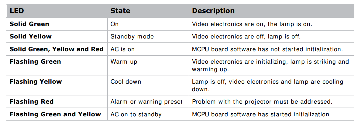
Turn the Projector On
- Set the breaker switch on the projector baseplate to the on position.
- When the projector reaches standby, on the touch panel controller, tap Home > Power. For more details on the specified voltage range, see Power requirements on page 78.
LED Power Up
The following table shows the expected behavior of the projector and the MCPU board power LED on power up.
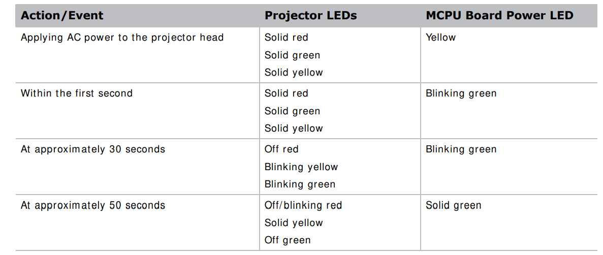
At approximately one minute and 15 seconds, the TPC indicates that it is connected and shows the home page.
Turn the Projector Off
- On the touch panel controller, tap the Home tab.
- Tap Power.
Work with Lamps
This section provides inform ation and procedures for optim izing lam p perform ance to ensure the brightest, m ost uniform im age possible for the life of the lamp.
Lamp Power
- On the touch panel controller, tap Menu > Lamp > Lamp Power.
- Use the slider or enter a value to adjust the lamp power.
- Tap OK.
Lamp position with Lamp Location
Use Lam pLOC to configure the lamp position and geometry when installing a new lamp in the project, or at any other time when the lam p perform ance needs to be optimized. Before adjusting Lam pLOC, measure the following criteria mare et:
- Make sure the lamp is on, and the douser (shutter) is open during adjustment.
- Christie recommends a 10-minute warm-up.
- Perform the LampLOC procedure. For more details, see Calibrate the lamp below.
Calibrate the lamp
The lamp slamp was recalibrated under the following conditions
- Aftemet lamp has been placed.
- After the projector has been moved and/ or jostled.
- After the lamp motor I MCB has been replaced.
- On the touch panel controller, tap Menu > Lamp > LampLOC.
- Tap Auto LampLOC.
- Adjust optical components if required.
Manually Adjust the Lamp Position
- On the touch panel controller, tap the Home tab.
- Tap Test Pattern and select 17pt White Field Test Point.
- Mount a light meter on a tripod and center it with the lens. The distance from the lens does not matter.
- An attenuator or an internal foil aperture may be required. Tap Menu > Lamp > LampLOC.
- Tap the directional arrows to adjust the value displayed in the Z fielduntil the brightness reading in front of the lens is maximized.
- Tap the directional arrows to adjust the values displayed in the X and Y fields until the brightness values in each field are maximized.
- For a finer adjustm ent, repeat steps 5 and 6 but take the readings at the center of the screen instead of at the lens.
View Lamp Information
To view a history of all previously installed lamps, on the touch panel controller, tap Menu > Lamp > Lamp History..
Track lamp intensity with LiteLoc
Use the LiteLoc feature to mmaintain constant level of brightness over the liflifetimethe lam plamphe touch panel controller, tap Menu > Lamp > Lamp Power.
- To adjust the lamp, use the slider or enter a value until the display is as bright as required.
- Tap OK. Tap Lamp Mode. Tap Constant Intensity. Notice the Lamp Power option is greyed out so you cannot adjust it.
- To readjust the lam p power, select Lamp Mode > Lamp Power. From the Lamp Power option, adjust the power setting as applicable.
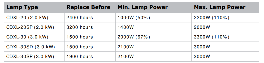
Lamp details
Record new lamp information
The lam.. p lampl numberis an alphanumeric field. Christie recommends a distinct and descriptive name for every individual lamp.
- On the touch panel controller, tap Menu > Lamp > Change Lamp.
- Enter a Lamp Type, Serial Number, and Hours Used.
- Tap Apply Lamp Change.
- Tap Continue
Add lamp end-of-life indicator
Specify the number of hours remaining for issuing an end-of-life indicator for the lamp. Touch the panel controller, tap Menu > Lamp > Lamp life warning at (hours).
- To specify the number of hours remaining before issuing an end-of-life indicator, enter a value, use the plus and minus buttons to increase or decrease the value. A value of zero disables the feature.
- Tap OK. When the specified number of hours is reached, a Lamp Hours – past expiry warning is issued.
Work with lenses
The lens mount secures the projection lens to the projector and provides setup adjustments to correct boresight, and control focus, zoom, and offset.s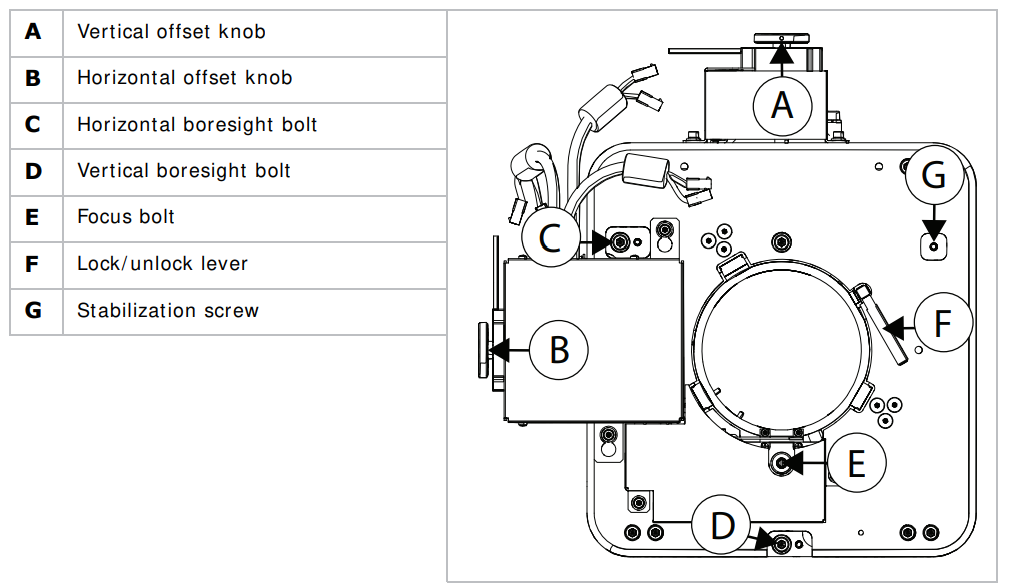
To electronically control the focus, zoom, and offset in the touch panel controller, tap the Lens tab.
Select a Channel
The projector uses pre-configured channels to determine how to display images from different sources. Each channel file contains the optimal processing and display settings for the source. Channels can be selected through the Home tab on the touch pad controller ( TPC)
Enable warping and blending
Use edge blending to combine several projected images into one single, seam less im age. Use
warping to project images on any surface shape.
- Create the warp and blend files using the Twist application.
- Upload the warp and blend files to the projector.
- On the touch panel controller, tap Main > Configuration > Geometry.
- To select a warp setting, tap Geometry Correction and tap the required warp.
- To select a blend setting, tap Edge Blending and tap the required blend.
- To select a black level blend setting, tap Black Level Blending and tap the required black level blend.
- To turn off warping, blending, or black level blending, tap Off.
Send error notifications to the specified device
If an error occurs on the projector, notifications can be sent to three different devices.
- On the touch panel controller, tap Menu > Communications > SNMP.
- Tap Trap IP Address 1. For the device you want to send error notifications to, enter the I P address.
- Tap OK. To add a second or third device, repeat steps 2 to 4.
- Select the options you want to m monitorptions include lamp fault, lam lamp, power, fan stall, and thermal.
Panel Controller
This section provides inform ainformationedures for using the projector menus. Use the projector m menus ato djust projector settings and view status information on the panel controller.
The touch panel controller ( TPC) is a touch- sensitive screen. Use the TPC to control the projector, manage, adjust the display, and view. Information is mountedon the rear of the projector and can be adjusted to improve the viewing angle. A side USB port can be used to download log files and install software upgrades. For rem ote applications, the TPC can be dism ounted from the projector and used with the optional cable to allow projector control from a m axim um distance of 100 ft (30 m )
Tab Structure
The touch panel controller ( TPC) windows are structured across a series of six tabs at the top of the display:
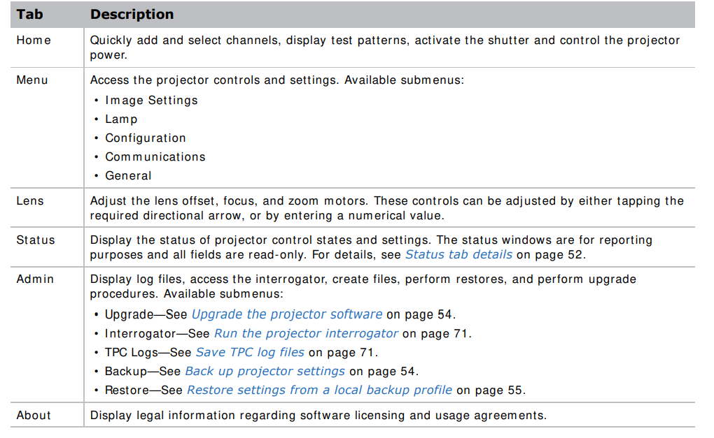
Menu tab details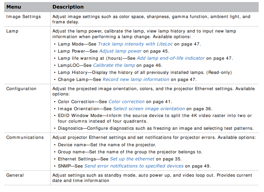
Status tab details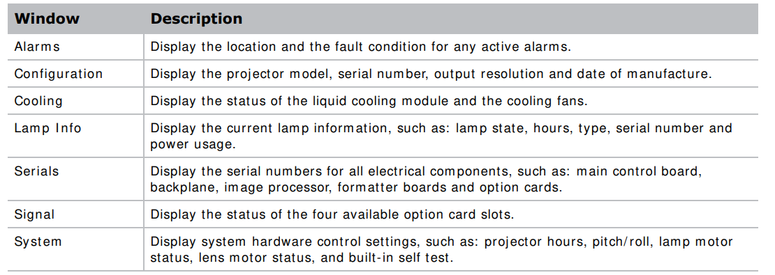

This section provides information and procedures for backing up, restoring, and upgrading projector files.
Upgrade the projector software
- On the touch panel controller, tap Admin > Upgrade. Tap Upgrade. To select the upgrade file, tap Browse. In the Select Package dialog, navigate to the location where the upgrade file is stored.
- Tap the upgrade file and tap Open. To automatically restart the projector when the upgrade is complete, tap Restart when update complete. Tap Install.
Back up projector settings
- On the touch panel controller, tap Admin > Backup.
- To back up the settings, tap a backup file.
- If required, enter or change the name.
- Tap OK. A message indicates the backup was successful.
Export backup settings to an external device
If exporting settings from the touch panel controller (TPC), insert a USB flash drive (properly formatted as FAT or NTFS) into the USB port on the side of the TPC, or if exporting settings from the PC application, skip to step 2. If using the TPC, you cannot save to the TPC’s on-board CF flash memory. You must export the settings to a USB flash drive. If using the PC application, you can export the files to a location on the hard drive, a USB flash drive, and so on.
- On the TPC, tap Admin > Backup. Tap Export. To save the file, in the Choose backup file location dialog, navigate to the location where you want to export the file. Tap Save.
Restore settings from a local backup profile
- On the touch panel controller, tap Admin > Restore.
- From the backup file list, tap the required file name
- Tap Restore.
- At the prompt, tap OK.
Default Settings
You need Service permission to complete the procedure.
- On the touch panel controller, tap Admin > Restore. Tap Defaults. Tap Restore.
- On the TPC, tap Admin > Restore. Tap Import.
- Tap the file to select it. Tap Open
Maintenance
Maintenance shutdown
This process is mandatory. Always perform these steps before beginning any inspection or main maintenance on the project.
- If the projector is operating, turn it off and allow it to cool for aminimum off 10 minutes.
- Set the projector breaker switch to the off position.
- Set the lampwer supply’s three breaker switches to the off positions.
- Disconnect the projector from AC power.
Ventilation and cooling
Vents and louvers provide ventilation, both for intake and exhaust. Do not install the projector near a radiator, heat register, or within an enclosure. To ensure adequate airflow, keep a minimum clearance of 50 cm (20 inches) around the projector and never block or cover the vents.
Inspect and clean the airflow interlocks.
The projector uses two airflow interlocks. Check and clean these switches to remove accumulated
dust or dirt that could impede movement.
- Lamp blower vane switch, located within the lamp cooling component.
- Extractor vane switch, located inside the top duct on the projector lid.
Inspect and Fill the Ccoolant Reservoir
- Shut down the projector.
- Remove the front top cover.
- Remove the radiator air filter.
- Disconnect the blower from the LCM pump.
- Disconnect the communications harness from the coolant reservoir.

- Disconnect the coolant hoses from the coolant reservoir.
- Remove the three screws securing the reservoir bracket to the projector base plate.

- Lift and remove the reservoir from the projector.

- Refill the reservoir as needed.
- Replace the cap.
- To reinstall the liquid cooling reservoir, repeat these steps in reverse order.
- Check for leaks, especially for any hoses that were removed around the filler cap.
- Check for proper flow from the liquid cooling module. For more details, see Maintenance shutdown on page 57.
Filtration
Replace the light engine air filter
This filter is located on the lens side of the projector behind the air filter cover. Check the condition of this filter monthly. Replace the light engine air filter when replacing the lamp, or sooner when operating the projector in a dusty or dirty environment.
- Release the two tabs on the air filter cover.

- Lift the cover enough for the bottom tabs to clear the frame and re-remove
- Slide the air filter out from behind the air filter cover and discard it.
- Insert the new air filter with the airflow indicator facing toward the projector.
- This ensures proper particle filtration.
- To complete the installation, align the bottom tabs and repeat these steps in reverse order.
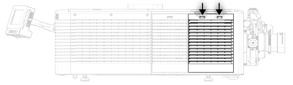
Replace the laminar airflow device filter
- Shut down the projector.
- Unlock and remove the front top cover.
- Unlock and remove the light engine lid.
- Remove the two screws securing the laminar airflow device filter (LAD) assembly to the bracket.
- Pull out and replace the LAD filter.

- To reinstall, repeat these steps in reverse order.
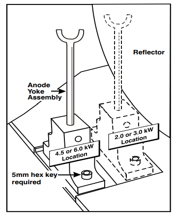
Adjust the Yoke Assembly
After installing the lamp, ensure optimization of the lamp, and check that the anode yoke is in the correct position for the lamp type.pe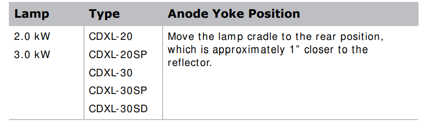
Install the projection lens
- Make sure the lens locking lever is in the up position.
- If at all, remove the lens cap from the lens.
- Slide the lens into the lens mount, aligning all connections.
- Secure the lens with the lens locking lever (down position).
- Calibrate the lens motors, as described below
Calibrate the lens motors
- Incorrect reporting of the lens motor position.
- Inability to use the full range of the lens motors.
- Lens motors are traveling outside of the pre-defined keep-out area.
- Damage to the projector. Calibrate the lens motor.
- To calibrate the lens motors, on the touch panel controller, tap Lens > Calibrate Lens Motors.
Reset lens to home position.
To reset the lens to the default home position, on the touch panel controller, tap Lens > Reset to Home Position.
Troubleshooting
The projector does not power on.
- Check the status LEDs on the rear corners of the projector for a fault condition.
- Use the touch panel controller (TPC) status menu to troubleshoot further.
Flicker, shadows, or dimness
- Make sure the shutter is fully open.
- Verify that a Lam pLOC calibration is not already in progress.
- Perform a Lam pLOC calibration.
Blank screen, no display of image
- Make sure the lamp is on.
- Make sure that all power connections are good.
- Make sure the shutter is fully open.
Cannot communicate with the projector
- Make sure the computer and the projector are both connected to the network.
- Make sure that all input devices have the same subnet mask and unique IP addresses.
Specification
This section provides detailed D4K2560 specifications. Due to continuing research, specifications are subject to change without notice.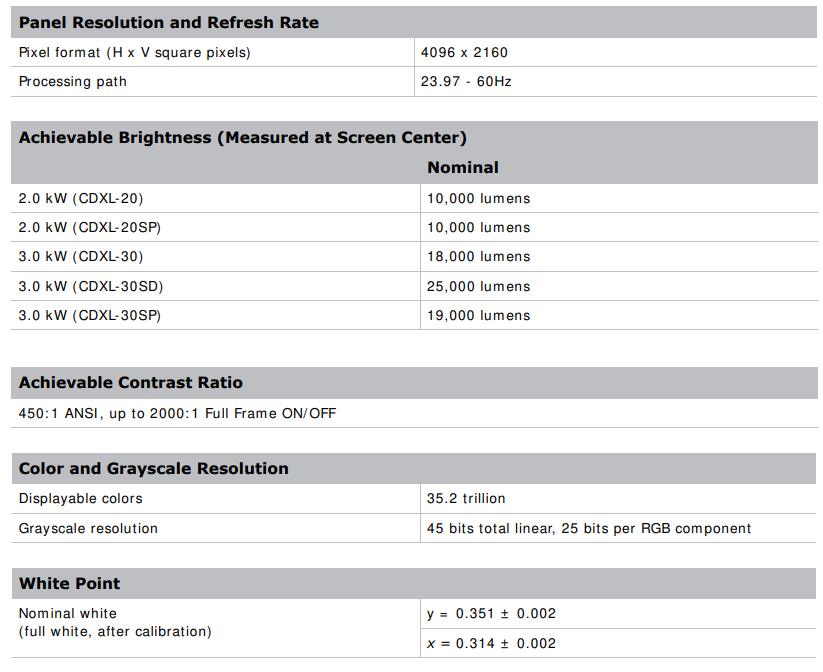
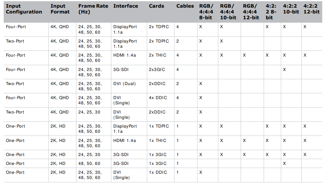
Optional Input cards
Control Signal Compatibility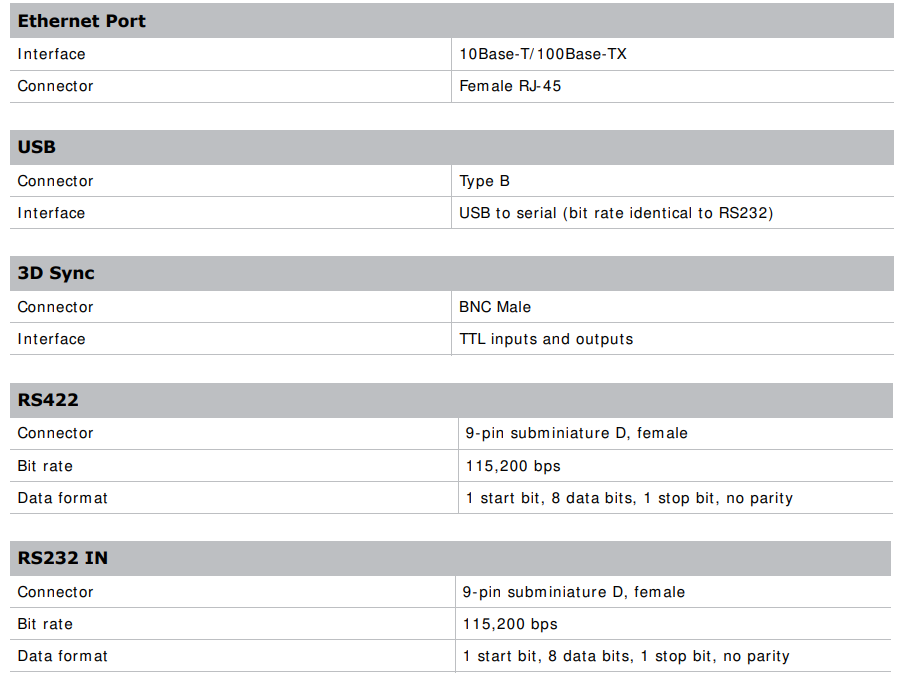
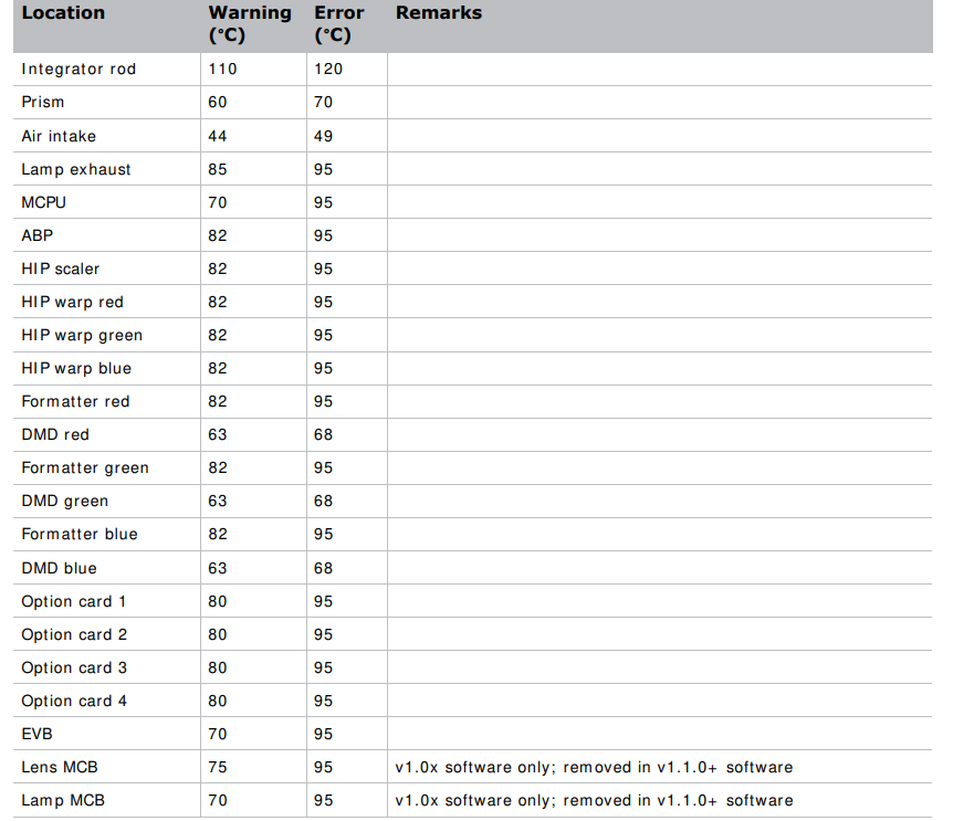
Temperature Sensor Thresholds
The project shuts down within one minute of an error threshold being reached.
 Power Requirements
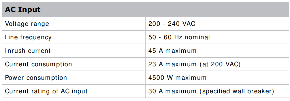 Lamp
Lamp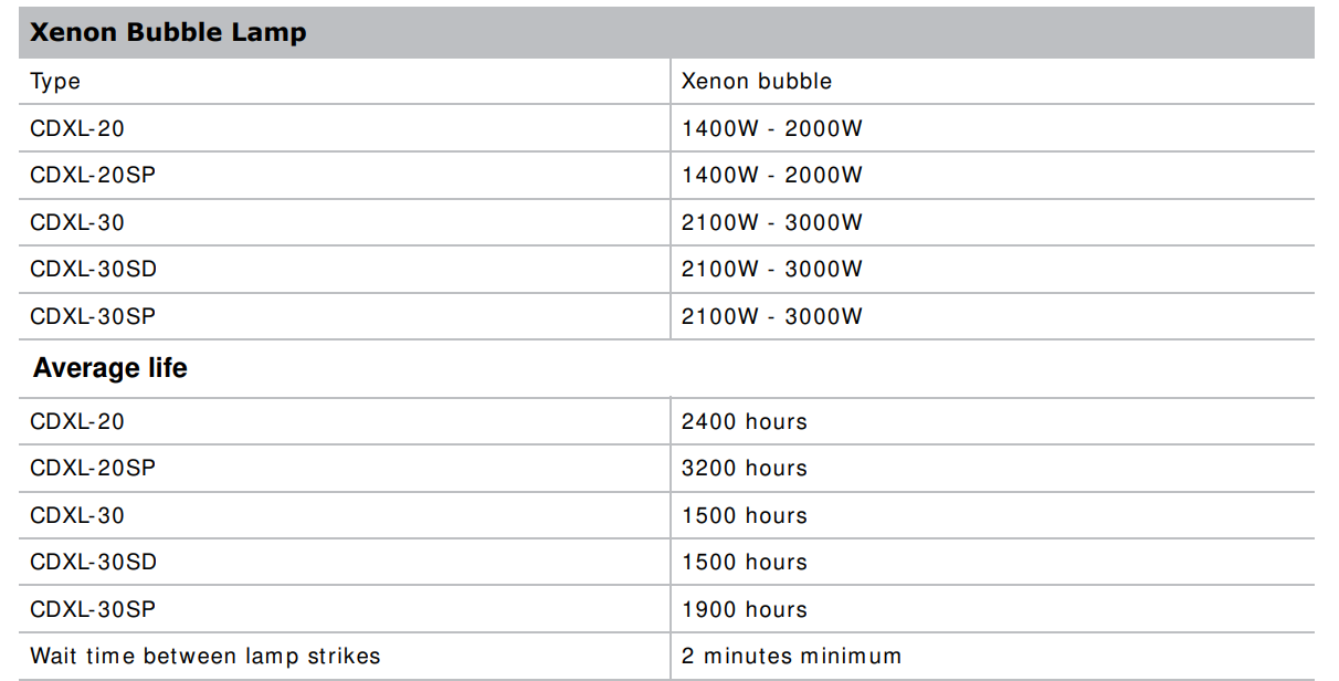
Physical Specifications

Customer Service
If you encounter a problem with your Christie projector, contact your dealer. To assist with the servicing of your projector, please refer to the information in the tables below and keep this information in your records.
 Website: www.christiedigital.com
- Ph: +61 (0) 7 3624 4888