
Clarke CIG1640 XX-Large Garage Assembly
Introduction
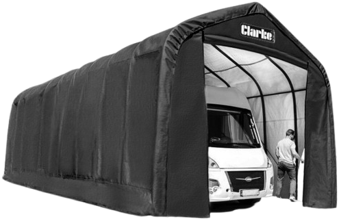
Thank you for purchasing this CLARKE XX Large Garage/Workshop. Before attempting to use this product, please read this manual thoroughly and follow the instructions carefully. In doing so, you will ensure the safety of yourself and that of others around you, and you can look forward to your purchase giving you long and satisfactory service.
Specifications
- Cover 305g Polyethylene, UV protected
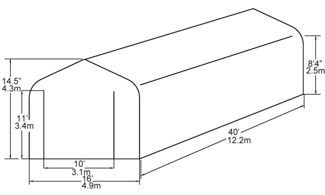
- Assembled dimensions 40 ft long x 16 ft wide x 14.5 ft high (12 m x 4.9 m x 4.3 m)
- Framee Round steel tubing, powder-coated
- Securing hardware: Easy hook anchors
- Weight 400.39 kgs
Safety Instructions
- DO NOT use this product in environments for which it is not intended (i, extreme cold, high winds, extreme heat, heavy rainfall,o r heavy snow, etc).
- DO NOT use open flames or cooking or heating devices inside or in proximity to the garage, including all types of stoves, gas heaters, gas lanterns, torches, fly killers, etc.
- The fabric will burn if left in continuous contact with a naked flame.
- DO NOT store flammable liquids (petrol, kerosene, propane, etc. in the garage or operate gas-powered vehicles/equipment in or around the garage.
- ALWAYS follow the following instructions for mounting the garage.
- Due to the height of this garage, an aerial platform or cherry picker will be useful and safer than using ladders.
- Ensure that any such platforms or ladders are operated on level ground.
- We advise that 6 people may be required to safely erect the frame and install the cover owing to the size and weight.
- Select a calm day to install the cover due to the high windage of the cover both during fitting and before it is totally secured in position.
Positioning & Installation
Siting & Positioning
Choose your garage location carefully. Check for overhead power lines, tree branches, etc. DO NOT install near roofs or other structures that may shed snow, icee or excessive run-off onto your garage. Erect your garage on level ground over a firm, level area.
Choose a dry location where dampness rising from groundwater in the environment will not undermine the protection offered by the garage. This will help to create a dry storage environment by insulating the garage storage space from ground moisture. Proper anchoring and keeping the cover tight and free of snow and debris are the responsibility of the user.
Assembly Layout
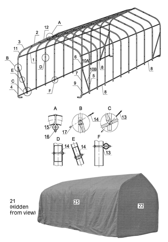
Have an overview of all parts before attempting construction, and make sure all components are supplied.
Assembly
- Place all parts in a clear area and arrange them on the ground. Check for completeness and for any transport damage.
- Remove all packaging materials and place them back in the box. Do not dispose of the packaging materials until assembly is complete.
Prepration
- Select the location for the garage.
- Make sure that at least six people are available to assemble this product.
- The foundation should be a concrete slab, concrete footings, pressure-treated timbers, or railway sleepers.
- The foundation area must extend at least 6 inches larger than the size of the garage.
- Bring the following tools (not supplied) to the assembly site:
- Screwdrivers
- Adjustable wrench or socket set
- Ladder(s)/cherry picker lift or platform
Assembling the Frame
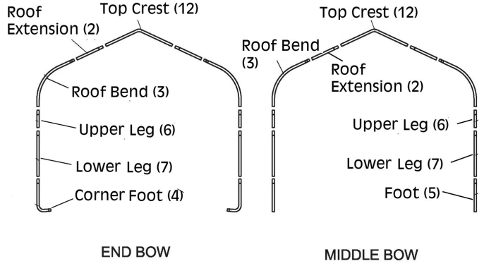
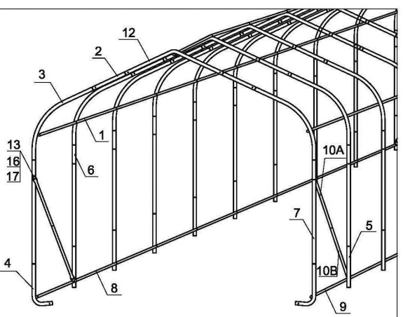
Assemble the End Bows and the Middle Bows as shown in Figure 1. Parts are attached using a 3″ bolt (14) and nut (16) at each junction – see End and Middle Bows below.
End Bows
Starting with two Corner Feet (4) (left side and right side) for each end, work your way up bolting connections together. Connect the Lower and Upper Legs (7,6), Roof Bend (3), and Roof Extension (2). Complete the End Bows (qty. 2) by connecting the left and right sides with the Top Crest (12). See Figure 1.
Middle Bows
The middle bows have the same procedure as above, except the lowest pieces are the feet (5). See Figure 1.
Connecting Bows
- At what will be the front of the garage, attach (10a+b) to the End Bow (center). Use bolts (13), washers (17), and nuts (16). Repeat on the opposite side. Do not completely tighten at this time because minor frame adjustments will be done later. Insert the tapered end of each (10b) into the end of each (10a), secure with nut (16) and bolt (14).
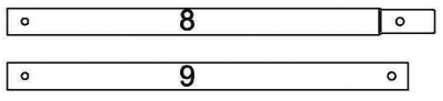
- At the base of that same End Bow, attach (8) to the base of (4). Swing the end of (10a+b) over to the connection of (5) and the end of (8). The tapered end of each (8) fits into the next (8). Use bolts (13), washers (17), and nuts (16) for this end of (10a+b) also. Do not completely tighten at this time because minor frame adjustments will be done later. Repeat these steps on the opposite end of the End Bow.
- Bolt all connections with bolts (14) and nuts (16) unless otherwise indicated. All nuts need to be on the inside of the frame
Rear End Bow
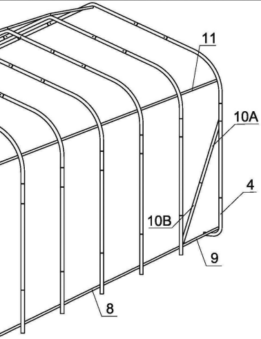
- At the base of the rear End Bow, fit the End Bottom Rail (9) to the Corner Foot (4). Attach Support Braces (10a+b) to the center of the last End Bow. Use bolts (13), washers (17), and nuts (16). Repeat on the other side of the End Bow. Do not completely tighten at this time because minor frame adjustments will be done later.
- At the base of the first Bow in from the end, attach End Bottom Rail (9) to the base of Foot (5). Swing the end of the Support Braces (10a+b) over to the connection of Foot (5) and the end of the Bottom Rail (8). The tapered end of Bottom Rail (8) fits into End Bottom Rail (9). Use bolts (13), washers (17), and nuts (16). Do not completely tighten at this time because minor frame adjustments will be done later. Repeat these steps on the opposite end of the End Bow. Continue assembling (8) between all of the Middle Bows until the final Middle Bow using the nuts and bolts (14) and (16). See Figure 4.
Top Rails
- Start at one side of the rear End Bow along the curvature of the Roof Bend (3). The End Top Rail (11) attaches to Roof Bend (3) on the inside of this curve. Insert Top Rail (1) inside End Top Rail (11) and attach to the Middle Bow. Continue attaching the Top Rails (1) tothe Middlee Bows and each other until you reach the end. Repeat these steps on the other side. Do not tighten bolts at this time. The bolts at the end will need to be removed when installing the cover fabric (door) and cover fabric (back). See Figure 5.
- When this portion of the frame is assembled and free-standing, move the assembled frame to your desired location using several people.

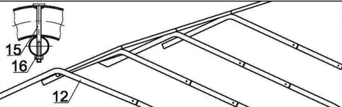
- The Top Crests (12) are at the top of the assembled Bows. To anchor that portion of the roof to the Bows, attach the Top End Rail (11) underneath the Top Crest (12) on the End Bow using a Coach Bolt (15) and a nut (16). Fit the Top Rail (1) into the Top End Rail (11) and connect to the top of the Middle Bow with Coachbolt (15) and nut (16). Continue connecting to the top until the last Middle Bow.

Squaring the Frame
- When the garage frame is assembled and in its final location, use the rope (19) to measure the distance between opposite corners, see Figure 7. Mark the rope and check the distance of the other two corners; the distance should be the same. If not, adjust the frame until it is.

Anchoring Instructions
- From the inside of the garage, place the anchors with Steel Cable (18) on all four corners. Place the remainder of the anchors on the inside of the Bows at intervals.
- If you are installing on asphalt, drill a deep 1” diameter hole to accept the anchor through the asphalt.
- If installing in dirt, drive the anchor into the soil using a hammer and the drive rod provided. The more you hammer, the more the anchor goes into the soil, compacting the soil around it. Remove the drive rod once you have established the maximum depth of the anchor.
- Pull upwards on the cable, rotating the anchor into a locked position. The anchor cuts into the undisturbed soil.
- After placing all the anchors, wrap the Wire Cable from each Anchor around the Bottom Rails and securely attach it to itself using clamps (25) (not shown).

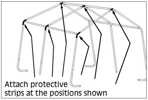
Protective Strips
In order to protect the fabric cover at points of wear, some adhesive tape is provided. This should be adhered to the frame at the positions shown after peeling off the adhesive backing strip.
- Cut the backing strip into suitable lengths of approximately 9” (25cm) and attach at the positions shown on every shoulder and on every apex.
Door Panel Fitting
- Before installing the cover (23), install the Door Panel (21) and Back Panel (22).
- (The Door Panel (21) has two zippers in it).
- .) the doorway of the frame, remove the bolts (14) and nuts (16) from the three Top Rails (1), top and sides.
- Place the door panel (21) over the arch of the front End Bow and wrap the material around the arch while bringing the slits to the inside of the frame. Place the Top Rail at the Top Crest (12) into the slit.
- Once the Top Rails (1) are in the slits on the sides and top, put the bolts (14) and nuts (16) back into all the locations that they were removed from, and tighten them down.
- Notice the white rope hanging out of the bottom of the Door Panel (21) on both sides. With two people, wrap the rope under the Corner Feet (4). Both of you are to pull up at the same time to tighten the door. When the door is snug, tie off the rope to the corner feet (4).
- Place the Back Panel (22) over the arch of the back End Bow and wrap the material around the arch while bringing the slits to the inside of the frame. Place the End Top Rail (11) at the Top Crest (12) into the slit.
- Once the End Top Rails (11) are in the slits on the sides and top, put the bolts (14) and nuts (16) back into all the places that they were removed and tighten them down.
- Attach the side of the Cover Back Panel (22) to the frame by using the 6 x Ball Tie Downs (24).

Cover Installation
- Position the Main Cover (23) face side up, being aware of the length and height of the frame in reference to the size of the cover.
- Use at least six people to help position the Cover (23) over the frame. It is suggested to have a person on a ladder at each end of the frame to assist with lifting.
- Centre the cover (23) over the frame. The internal rope should be in the front and rear (outside). The punched holes should be positioned on the inside of the garage. Centre the cover on all four sides.
- Loosen the four turnbuckles (20). Tie the ropes loosely to the turnbuckles (20). Check to be sure the cover is still centered and has the same amount of overlap on the front and the back. See Figure 13.
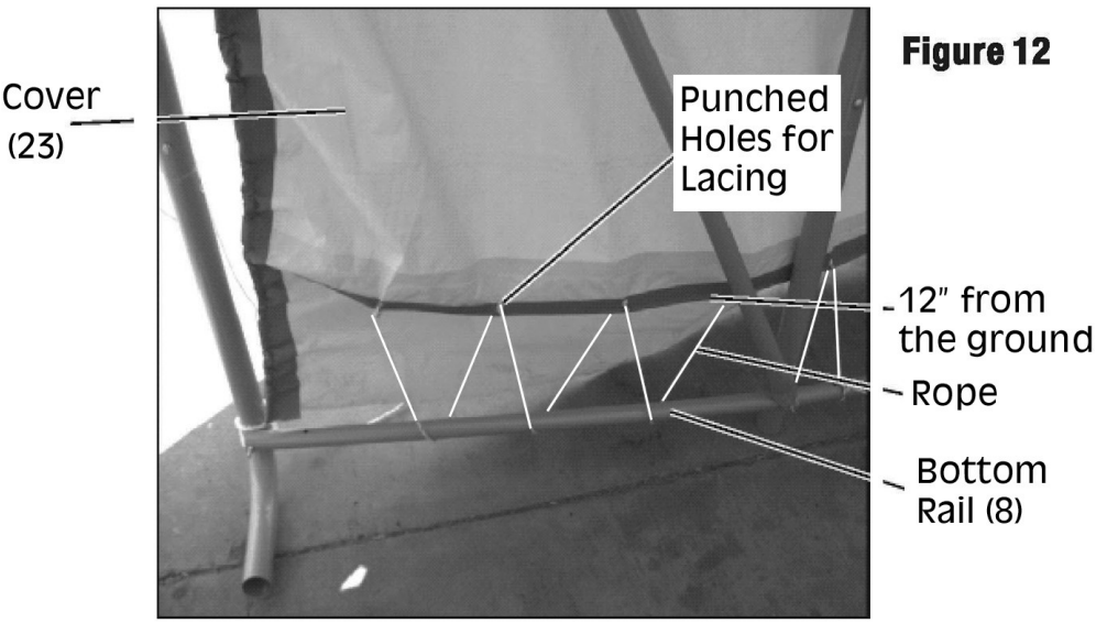
- The area where the rope comes out of the cover (23) should be about 12″ from the ground. See Figure 12.
- Pull the rope tighter, using a few knots to secure it to the turnbuckle (20). Twist the turnbuckle (20) to tighten the rope.
- Check monthly & tighten if needed. See Figure 13.
- When the cover (23) is aligned, fasten it to the frame using the rope (19).
- Start by lacing the end of the rope through the first punched hole in the cover. Pass the rope under the Bottom Rails (8), and continue down the garage, creating a laced effect.
- When laced to the end, that will be the End Bottom Rail (9,) tie off at the end. Work your way ba,ck tightening the lacing by pulling the rope down, creating a snug fit.
- When you get to the other end, tie off and trim off any extra rope.


Care & Maintainance
This garage is NOT designed to support heavy snow. Snow or ice accumulation may cause your garage to collapse. To avoid overload, brush snow and ice off trooftoptop Clarke CIG1640 XX-Large Garage Assembly with a broom or mop to prevent collapse with the resultant damage to property or personal injury. NEVER clear the roof of snow or debris from inside the garage. DO NOT use hard-edged tools or instruments, such as rakes or shove,ls to remove snow. These can cause punctures to the cover.
DO NOT use bleach, alkaline, or harsh detergents for cleaning. Doing so will damage the material. Soap and warm water are recommended. To reduce the risk of burning and avoid damage, DO NOT cook, smoke, ref,uel or use any open flame devices in or around the garage.
Storage
NEVER run the engine of any vehicle or machine inside a Clarke CIG1640 XX-Large Garage Assembly closed garage. Ensure that there is adequate ventilation for engines or for any work with paints, ,cleaners etc. by opening the door panel and keeping it raised. Take steps to avoid the buildup of condensation inside the garage. Cool, damp winter days and moisture from the breath and body heat of personnel may cause condensation on the inside of the top cover of the garage.
A supply of fresh air through the doorway will at least partly remove this issue. Condensation will be much less of an issue during the summer months. If storing a vehicle in your garage over the wint,er months we recommend the use of a secondary lightweight cover over your vehicle.
Component Parts

Guarantee
This product is guaranteed against faulty manufacture for a period of 12 months from the date of purchase. Please keep your receipt, which will be required as proof of Clarke CIG1640 XX-Large Garage Assembly purchase. This guarantee is invalid if the product is found to have been abused or tampered with in any way, or not used for the purpose for which it was intended. Faulty Clarke CIG1640 XX-Large Garage Assembly goods should be returned to their place of purchase; no product can be returned to us without prior permission. This guarantee does not affect your statutory rights.
Environmental Recycling
One of the most damaging sources of environmental pollution is oil products. Never throw away used oil with domestic refuse or flush it down a sink or drain. Collect any Clarke CIG1640 XX-Large Garage Assembly oil in a leak-proof container and take it to your local waste disposal site.
Customer Service
- Tel: 0208 988 7400
- Website: parts@clarkeinternational.com
- Visit: service@clarkeinternational.com
FAQs
What are the dimensions of the Clarke CIG1640 XX-Large Garage?
With dimensions of roughly 16 feet by 40 feet, the CIG1640 provides plenty of room for storing automobiles, tools, machines, or outdoor gear.
How long does assembly take?
With two to three people, assembly typically takes six to ten hours, depending on site preparation, weather, and experience.
Can the garage be installed on uneven ground?
It’s advisable to install the garage on a flat, level surface (concrete, gravel, or compacted soil) for stability and good alignment.
Can the cover be replaced if damaged?
Indeed, authorised distributors or Clarke Parts & Service offer replacement coverings and individual parts.
How do I anchor the garage to the ground?
Make use of the optional concrete fixings or the supplied ground anchors. Anchors of the auger type are advised for soft soils. To avoid wind damage, always make sure the anchoring is secure.