
Hayward C2030 Top Manifold Cartridge Filters
Safety Instructions
- Do not operate the water circulation system if a system component is assembled improperly, damaged,
missing, or not a genuine Hayward component. - Before performing maintenance on the water circulation system, verify all system and pump controls
are in the OFF position, and the filter manual air relief valve is in the OPEN position. - Use ONLY Hayward clamp system components: DEX2421JKIT clamp assembly, DEX2421J2 nut/bolt
assembly, and a DEX2422Z2 metal reinforced seal. - Before starting the system pump, ensure the filter manual air relief valve body is in the LOCK position in the filter upper body.
- Before starting the system pump, verify that all system valves are set in a position to allow water from the filter to return to the pool.
- Before starting the system pump, the manual air relief valve must be in the OPEN position.
- When starting the pump, do not stand over or near the filter.
- Return to filter to close the manual air relief valve only when a steady stream of water (Not air or air and water mix) is discharged from the manual air relief valve.
- Do not change the filter control valve position while the system pump is running.
General Information
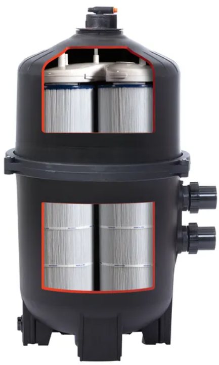
Your Hayward SwimClearTM cartridge filter combines superior water filtration with ease of operation and totally corrosion-resistant construction. With an inflation ratio of p to ngs9,0009000 gallons (34,000 liters) per hour, they are designed for continuous or intermittent operatisuitable on, suitable for installation above or below the pool water liand compatible with both fresh and saltwater swimming pools or spas. SwimClear™ filters utilize multiple reusable, reinforced polyester filter cartridge elements to provide a high degree of water clarity and long filter cycles with minimum care.
| A | REQUIRED CLEARANCE | |||||
| “B” SIDE | “C” ABOVE | |||||
| IN | CM | IN | CM | IN | CM | |
| C2030 | 32.5 | 83 | 18 | 46 | 15 | 38 |
| C3030 | 34.5 | 88 | 18 | 46 | 16 | 41 |
| C4030 | 40.5 | 103 | 18 | 46 | 18 | 46 |
| C5030 | 46.5 | 118 | 18 | 46 | 22 | 56 |
| C7030 | 52.5 | 133 | 18 | 46 | 28 | 71 |
Cartridge Filter
| MODEL | EFFECTIVE FILTRATION RATE | DESIGN FLOW RATE Residential Commercial | ||
| FT2 | M2 | GPM | LPM | |
| C2030 | 225 | 20.9 | 84 | 318 |
| C3030 | 325 | 30.2 | 122 | 462 |
| C4030 | 425 | 39.5 | 150 | 568 |
| C5030 | 525 | 48.8 | 150 | 568 |
| C7030 | 680 | 63.2 | 150 | 568 |
Installtion
This product should be installed and serviced only by a qualified pool professional.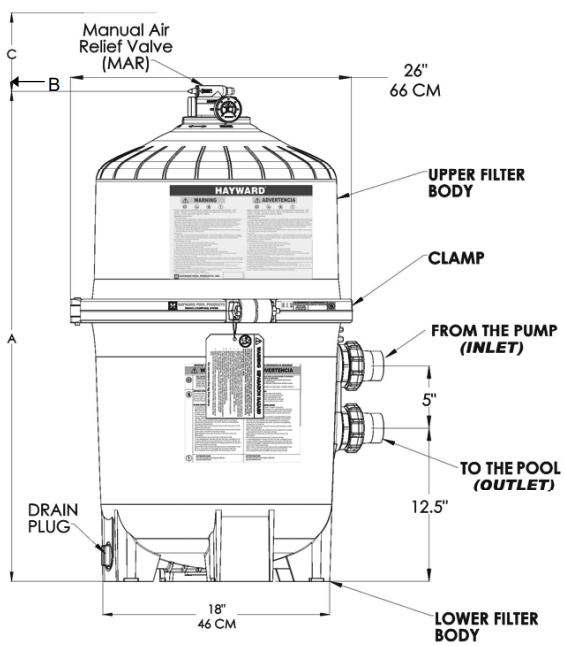
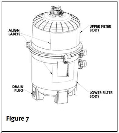
- Position the filter body such that all operations and safety labels are visible.
- Position the filter so that filter will drain by gravity.
- If practical, place the pump and filter in the shade to shield them from continuous, direct heat from the sun.
- Connect the pool suction plumbing between the skimmer, pool suction outlet (from the pool), and the pump.
- Connect the pump discharge (pump OUTLET) to the top port of the filter (filter INLET).
- Connect the bottom filter port (filter OUTLET) to the pool return plumbing lines.
- Do not locate pump controls over or near the filter.
- Verify water discharge from the manual air relief valve(MAR) is directed away from electrical devices.
Filter System
Before Starting the Pump
- Use ONLY Hayward clamp system components: DEX2421JKIT clamp system, DEX2421J2 nut/bolt assembly, DEX2422Z2 metal reinforced seal. Non-Hayward clamp components may fail in use, causing explosive component separation.
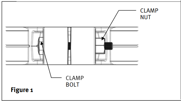
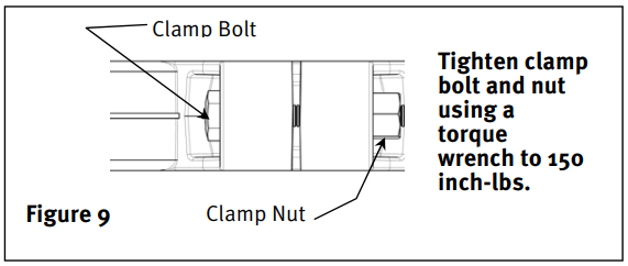
- Verify that the upper and lower filter bodies are properly secured with the filter body clamp. Never rely on hand-tightening the clamp nut to the clamp bolt. Using a ¾” socket on a torque wrench, torque the clamp nut to the clamp bolt to 150 inch-lbs.

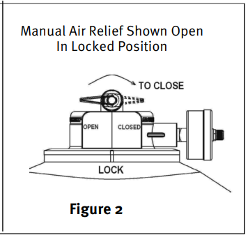
- Verify that the filter manual air relief body is in the LOCK position, and no filter components are missing, damaged, or not genuine Hayward components. (See Fig. 2)
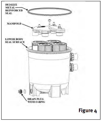
- Close the filter drain. The filter plug requires an O-ring seal. (See.g 4)
- Open all system valves to allow water from the pool to the filtration system and from the filter to return to the pool.
- Place the manual air relief valve ithe n the OPEN position.
Starting Pump
- When starting the system pump, do not stop the filter. If water leakage at the tilter tank clamp, immediately turn off all system circulation pumps and all electrical power. Do not return to the filter until all water leakage has stopped. Reassemble the clamp system per the instructions on page 7 in this owner’s manual to stop op leak.
- Return to filter to CLOSE manual air relief valve only when a steady stream of water (not a mixture, air and water) is discharged from the manual air relief valve.
Operation
Filtration starts as soon as the flow is steady through the filter. As the filter removes dirt from the pool water, the accumulated dirt causes a resistance to flow. As a result, the gauge pressure will rise and the flow will decrease. When the pressure rises between 7 and 10 psi (.49 – .69 bar) above the starting pressure, or when the flow decreases below the desired rate, clean or replace the filter cartridge elements. Once your filter is running and there is a pressure reading, line up the green arrow with the current reading. (See Fig. 3).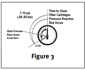 When the pressure rises to or above the red or second arrow, it is time to clean or replace your filter cartridge elements.
Maintaining Your Filter
- Turn off all system circulation pumps and all electric power on the equipment pad.
- Set all system valves in a position to prevent water flow to the filter.
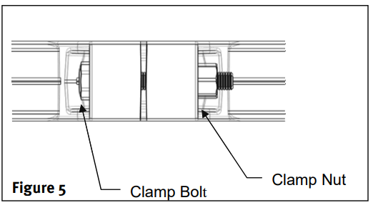
- The manual air relief valve must be placed in the OPEN position. (Fig 6)
- Remove the filter drain plug (Fig. 4) and drain water from the filter.
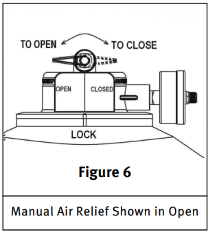
- Using 3/4” wrenches or hex sockets, loosen and remove the clamp nut and the clamp bolt. (Fig 5)
- Holding both ends of the filter clamp, carefully spread the clamp ends. Remove the clamp by liftitng t over the upper filter body. Do not drop the clamp during removal, because the clamp could be damaged. Do not strike the clamp with metal tools, as they can damage the clamp.
- Lift off the upper filter body. Do not use the pressure gauge to lift the upper filter body.
Removing
- Remove the top Manifold, which is exposed when the upper filter body is removed. (Fig 4)
- Remove the filter cartridge elements by using a slight rocking motion and lifting.
- Clean filter cartridge elements.
Cleaning
The Cartridge filter element can be cleaned by washing inside and outside with a garden hose. After housing the g cartridge, for best results, carefully brush the pleated surface to remove fine particles. Do not pressure wash, as it can damage the filter element. You may find some debris on the cartridge pleats, which may not have been removed with hosing.
Re-Assembly Instructions
- Flush and drain any dirt or debris from the bottom of the lower filter body.
- Flush any dirt or debris from the upper filter body and from around the manual air relief area.
- Carefully replace the cartridges over the hubs on the bottom seal plate.
- Place the top manifold securely on top of the cartridges, aligning the return pipe with the port in the manifold.
- Remove the filter tank seal.
- With a clean cloth, wipe the lower filter body seal surface and clean the seal of all dirt and debris. (Fig 4) Do not use a solvent.
- With a clean cloth, wipe the upper filter body seal surface.
- Place the metal reinforced seal on the lower filter body.
- Place the upper filter body on the metal reinforced seal and the lower filter body in a position that allows all operation and safety labels to be clearly visible, and the upper filter body to be centered on the lower filter body. Press down firmly and evenly on the upper filter body to seat the seal.
- Replace the filter clamp around the upper and lower filter bodies. Hold the clamp ends to position the clamp on the filter bodies with the clamp ends adjacent to the safety and operation labels on the filter bodies.
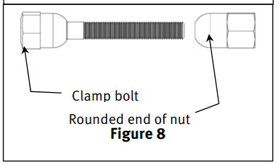
- Insert the clamp bolt through the clamp ends and thread the clamp nut onto the clamp bolt with the rounded end of the nut towards the ends of the clamp.
- Never rely on hand tightening of the lamp nut to clamp the bolt. Using a 3/4” socket on a torque wrench, torque the clamp nut to the clamp bolt to 150 inch-lbs.
- Follow the operation Instructions for “Starting the Pump and Filter System.”
Removing the Valve
- Turn off all system circulation pumps and all electric power on the equipment pad.
- Set all system valves in a position to prevent water from flowing to the filter.
- The manual air relief valve must be placed in the OPEN position.
- Wait until all water leakage has stopped.
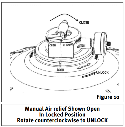
- Grasp the MAR body at the flats, turn the MAR counterclockwise until the indicator on the MAR flange is aligned with the “UNLOCK” position on the upper filter body.
- Pull straight up to remove the MAR. A slight rocking motion may help.
This product should be installed and serviced only by a Hayward C2030 Top Manifold Cartridge Filters qualified pool professional.
Re-Installing
- Check the o-ring seals, replace as needed.
- With a clean cloth, wipe the upper filter body and the o-ring groove. Remove all dirt and debris.
- Align the notch in the MAR Flange with the notch on top of the upper filter body.
- Press the MAR straight down into the upper filter body.
- Turn the MAR clockwise until the indicator is aligned Hayward C2030 Top Manifold Cartridge Filters with the “LOCK” position on the upper filter body.
- Verify the MAR discharge points are away from all electrical connections.
Winterizing
This product should be installed and serviced only by a Hayward C2030 Top Manifold Cartridge Filters Top Manifold Cartridge Filtersqualified pool professional. In areas where subfreezing temperatures can be expected, the filter should be drained to protect the filter from damage.
- The filter should be disassembled, and the filter cartridge elements cleaned or replaced.
- Follow directions under FILTER DISASSEMBLY INSTRUCTIONS
- Then follow REMOVING CARTRIDGES per instructions
- Reassemble per FILTER RE-ASSEMBLY INSTRUCTIONS.
- Be sure to leave the drain plug unattached during the winter season to avoid cracking the filter body
Service & Repairs
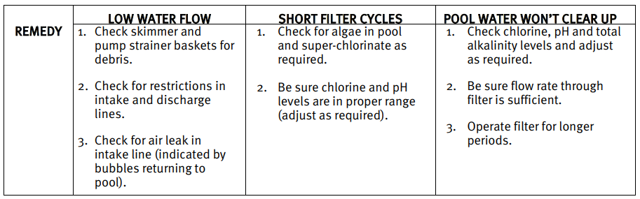
| SUGGESTED POOL CHEMISTRY LEVELS | |
| pH | 7.2 to 7.8 |
| TOTAL ALKALINITY | 80 to 120 ppm |
| CALCIUM HARDNESS | 200 to 400 ppm |
| COMBINED CHLORINE | .2 ppm Maximum |
| CHLORINE (STABILIZED) | 1.0 to 3.0 ppm |
| CHLORINE STABILIZER (Cyanuric Acid) | 60 to 80 ppm |
Problem Solving
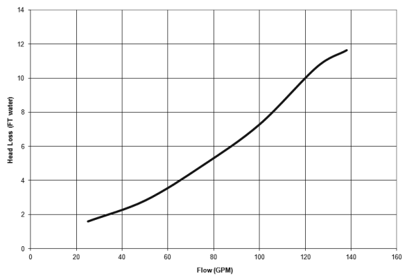
Head Loss Top Manifold
Parts
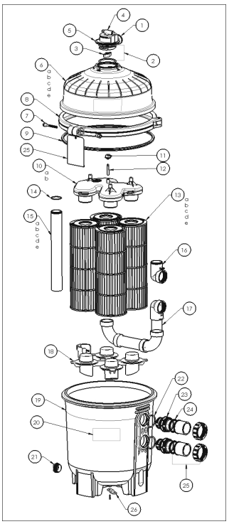
| Item | Part No. | Description |
| 1 | ECX2712B1 | Pressure Gauge |
| 2 | DEX2420Z8A | O-Ring Kit (Set of 2) |
| 3 | CCX1000N | Air Relief Valve Nut |
| 4 | CCX1000V | Manual Air Relief w/O-Ring |
| 5 | DEX2420MAR2 | Manual Air Relief Assembly |
| 6a | DEX2420BTC | Upper Filter Body C2030 |
| 6b | DEX3620BTC | Upper Filter Body C3030 |
| 6c | DEX4820BTC | Upper Filter Body C4030 |
| 6d | DEX6020BTC | Upper Filter Body C5030 |
| 6e | DEX7220BTC | Upper Filter Body C7030 |
| 7 | DEX2421J2 | Clamp Bolt & Nut |
| 8 | DEX2421JKIT | Clamp System including: Clamp, Clamp Nut, and Bolt, Hang tag, Metal Reinforced Seal, and Labels |
| 9 | DEX2422Z2 | Metal Reinforced Seal |
| 10a | CX3030C | Top Manifold for C2030, C3030 and C4030 |
| 10b | CX5030C | Top Manifold for C5030, and C7030 |
| 11 | CX3000J1 | Air Relief Filter |
| 12 | CX2030Z3 | Air Relief Tube |
| 13a | CX481XRE | Cartridge Element C2030 1 of 4 Required |
| CX481XREPAK4 | Cartridge 4 pack C2030 | |
| 13b | CX580XRE | Cartridge Element C3030 1 of 4 Required |
| CX580XREPAK4 | Cartridge 4 Pack C3030 | |
| 13c | CX880XRE | Cartridge Element C4030 1 of 4 Required |
| CX880XREPAK4 | Cartridge 4 Pack C4030 | |
| 13d | CX1280XRE | Cartridge Element C5030 1 of 4 Required |
| CX1280XREPAK4 | Cartridge 4 Pack C5030 | |
| 13e | CX591XRE | Cartridge Element C7030 1 of 8 Required |
| CX591XREPAK4 | Cartridge 4 Pack C7030 1 of 2 Required | |
| CX7020M | Mid plate Connector C7000 series only | |
| 14 | DEX2400Z5 | O-Ring |
| 15a | CX3031F6 | Outlet Pipe C2030 |
| 15b | CX3031F7 | Outlet Pipe C3030 |
| 15c | CX3031F8 | Outlet Pipe C4030 |
| 15d | CX3031F9 | Outlet Pipe C5030 |
| 15e | CX3031F10 | Outlet Pipe C7030 |
| 16 | CX3030F | Inlet Elbow |
| 17 | CX3030H | Assy, SwimClear Piping |
| 18 | CX3030D | Bottom Seal Plate |
| 19 | DEX2420ATC | Lower Filter Body |
Warranty
Any warranty claim should be accompanied by proof Hayward C2030 Top Manifold Cartridge Filters of purchase, indicating the date of purchase. We would therefore advise you to keep your invoice.
In order to make a claim under the warranty and in order to request repair or replacement of an article, please ask your dealer. Parts damaged by wear and tear: gasket and cell plate coating.
Customer Service
- Ph: 1-800-657-2287
- Website: www.haywardcommercialpool.com
FAQs
What is the purpose of the SB27150 90 Degree Bezel Kit?
When installing Dometic ventilation equipment at a 90-degree angle, the SB27150 bezel kit is made to offer a neat, safe, and expert finish, enhancing both airflow and visual appeal.
Which Dometic models is this bezel kit compatible with?
Consult the product handbook to confirm compatibility with your particular model.
How do I properly align the bezel during installation?
Before fastening screws, ensure accurate alignment using an angle guide or carpenter’s square.
Is the bezel kit waterproof or weather-resistant?
When installed properly, the SB27150 bezel assembly offers a sealed fit and is suited for outdoor use. For better protection, more waterproof sealant should be applied around the edges.
Can I install this bezel kit myself, or should I hire a professional?
Self-installation is feasible if you are familiar with basic do-it-yourself projects and can follow directions. If in doubt, seek advice from a qualified installer, particularly when it comes to electrical or ventilation connections.
Where can I find the full installation manual?
The product box contains all of the installation instructions. Alternatively, you can obtain the PDF handbook from the official Dometic website.
Can I purchase replacement parts for the bezel kit?
Yes, authorised Dometic dealers and their online site sell replacement screws and mounting accessories.