
Hayward Sheer 500 LED Lighting Water Feature

Introduction
The Hayward Sheer 500 is a waterfall water feature designed to incorporate color LED light(s) to enhance your backyard pool or spa experience with stunning lighting effects and soothing sounds of falling water. The Sheer 500 must be installed as specified by these instructions. Please follow ALL of the instructions enclosed with this unit. It is recommended to keep the unit in its original packaging until the site is prepared for installation.
Safety Instructions
- All electrical wiring MUST be in conformance with applicable local codes, regulations, and the National Electrical Code (NEC).
- To reduce the risk of electric shock, do NOT use an extension cord to connect the unit to electric supply.
- Provide a properly located electrical receptacle.
- Before working on any electrical equipment, turn off the power supply to the equipment.
- Risk of Electric Shock. Opening the light can cause shock, burns, and severe injury.
- Light has user-serviceable parts inside. Do not open the light.
- Permanently installed pools and spas are those constructed in or partially in the ground, and all others capable of holding water in a depth greater than 42 in (1.07 m).
- Storable pools and spas are those constructed on or above the ground and capable of holding water to a maximum of 42 in (1.07 m).
- Electrical shock hazard. Damage to wiring can cause severe injury or death.
- To reduce the risk of electric shock, replace damaged wiring immediately.
- Locate conduit to prevent abuse from lawn mowers, hedge trimmers, and other equipment.
What’s Included
Refer to the table below for a list of all items included with the Hayward Sheer 500.
| INCLUDED | ||
| Item # | Part Description | Qty |
| 1 | Waterfall Assembly | 1 |
| 2 | LED Light Installation Tool | 1 |
| 3 | Extractor Tool | 1 |
| 4 | Lid, Collar & Ext. Collar Set (Tan/Grey) | 1 |
| SOLD SEPARATELY | ||
| Item # | Part Description | Qty |
| 1 | LFCUS11100 LED Light Assembly 100′ | 1 |
| 2 | LFCUS11150 LED Light Assembly 150′ | 1 |
| 3 | Black Lid & Collar Set | 1 |
| 4 | White Lid & Collar Set | 1 |
| 5 | Dark Grey Lid & Collar Set | 1 |
| 6 | Grey Lid & Collar Set | 1 |
| 7 | Rock Trap | 1 |
Installation
Preparation
Installation of the waterfall requires the use of.
- Pump
- Cartridge filter (Do NOT use sand or DE filter)
- Flow control valve
- Low-voltage transformer and (optional) single-gang junction box
- LED Light control system (wall switch or automation control)
- PVC Pipe and 1 in. electrical conduit (refer to table below)
| Waterfall Length | Supply Pipe Size |
| Less than 18 in. | 11/2 in. |
| 18 in. – 4 ft | 2 in. |
| Greater than 4 ft | 3 in. |
Mechanical
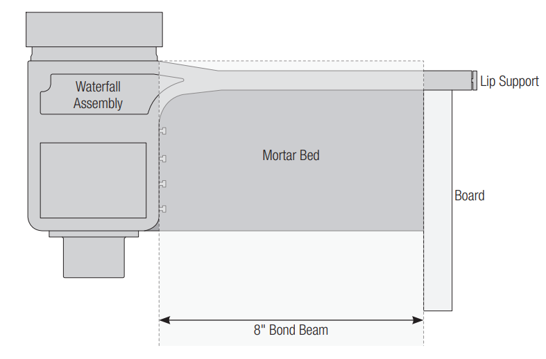
Refer to the diagram below for waterfall dimensions before roughing in plumbing and electrical lines.
Note: Refer to page 14 for waterfall length dimensions and the number of lights.
- Step 1: Rough-in plumbing and electrical lines. See the overview diagram on pages 5-6.
- Step 2: Cut a notch in the bond beam and attach a board as shown below. Make sure the board is level, as it will be used for setting the level of the waterfall.

- Step 3: Fill the notch with mortar and set the waterfall in the mortar as shown below. Make sure that the lip support is in place to prevent debris from getting into the waterfall. Note that the edge of the waterfall lip should clear the finished tile line by 3/4″. The lip should be level on the board and fully supported by the mortar.
- Step 4: Wait for the mortar to fully cure and then remove the board.
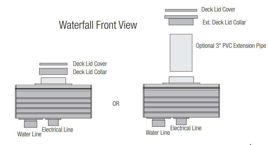
- Step 5: Glue the ext. deck lid collar onto the waterfall unit with PVC glue. If the waterfall is installed in a raised wall, a 3″ PVC pipe can be used to extend the distance between the top of the waterfall unit and the deck surface, allowing access to the LED light.
- Step 6: Glue the water line(s) and electrical line(s) to the waterfall.
- Step 7: Install the coping and tile finish. Note that it may be necessary to add filler on top to level out the top of the waterfall lip with the top of the bond beam.
- Step 8: Once installation is complete, the waterfall lip support can be removed.

Plumbing
Refer to the diagram below for a basic installation overview. If plumbing multiple waterfalls in-line, use a looped plumbing configuration as shown on the next page.
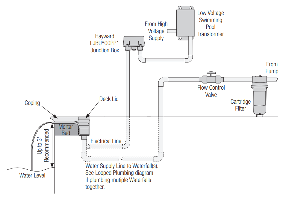
Refer to page 2 when determining the pipe size for the water supply line. 2″ plumbing is required when using the optional rock trap (not pictured above). To prevent damage from debris, the waterfall requires a cartridge filter to be plumbed in the water supply line. DointoOT use a sand or DE filter. It is recommended to plumb a flow control valve and a water supply line in order to control the flow of water to the waterfall and achieve the desired water effect. If using a variable speed pump, then a flow control valve may not be needed.
Looped Plumbing
When plumbing multiple waterfall systems together, a looped plumbing method, shown below, should be used. This will ensure that pressure on all waterfalls is equalized and they will all have the same water effect.
Electrical Wiring
Refer to the wiring overview diagram below and the following pages for wiring steps.
The waterfall’s LED Light (sold separately) requires the use of a low-voltage swimming pool transformer (not included). When considering the number of transformers required, note that one light is 25W, and the load on a transformer should not exceed 80% of the maximum wattage.
| Number of Lights | Type of Transformer |
| 1-2 | 70W |
| 3-9 | 300W |
| 10+ | Multiple Transformers |
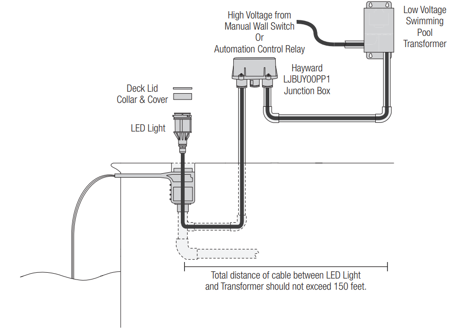
Running the Cable
With the waterfall unit now installed, it is time to run the wiring cable from the LED light to the junction box or low-voltage transformer. Note that the maximum cable length between the waterfall and the low-voltage transformer should not exceed 150 feet.
Cable runs that are 100 feet or less should use 14-gauge wire, and more than 100 feet should use 12 gauge wire. Feed the 12-gauge electrical line from the waterfall to the junction box or transformer. At the junction box or transformer, cut the extra cord, leaving enough for wiring.
If using an optional junction box, run the cable from the junction box to the low-voltage transformer. Cut the extra cord at both the junction box and the transformer, leaving enough for wiring. Verify that all power is off and then run the cable from the power source – either a manual wall switch or an automation control relay – to the low voltage transformer. Cut the extra cord at both ends, leaving enough for wiring.
Junction Box Wiring (optional)
- A junction box is useful if multiple waterfall LED Lights will be wired together. To make connections easier, it is recommended to use Wago 221 Series lever nuts (pictured below), but standard electrical wire nuts can also be used.

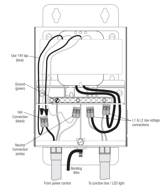
Low Voltage Transformer Wiring
- Refer to the wiring diagram below for Hayward 300W transformers. For other listed swimming pool transformers, refer to the instructions included with the transformer. Be sure to follow all NEC and local codes when wiring.
Power Control Wiring
- When wiring to a wall switch or automation control, follow the directions in the manual provided
with that product. When wiring to a Hayward Omni control relay or an Omni Smart Relay, refer to the graphics below. Be sure to follow all NEC and local codes when wiring.

Set the LED Light in the Waterfall
- With wiring complete, the LED light is ready to be set in the niche. Lubricate the O-rings on the light with the supplied lubricant, then use the light installation tool (shown on the right) to gently press the light into the waterfall unit until the ribs are aligned. Then, twist the light 90 degrees clockwise until it locks in place.

Seal with Deck Lid Cover
- Install the deck lid cover on the top of the collar with a ribbon of silicone adhesive.
Operation
When operating the waterfall, it is recommended to keep the water flow at 15 gpm per foot, but the
gpm can vary as the ideal water effect i,s up to the user’s personal preference. See graphic below.
Manual Control
When the light has been off for over 60 seconds and is first turned on, it will come on in white for 15 seconds, then go to the last fixed color or color show that was running.
- Show-Voodoo Lounge
- Fixed-Deep Blue Sea
- Fixed-Royal Blue
- Fixed-Afternoon Skies
- Fixed-Aqua Green
- Fixed-Emerald
- Fixed-Cloud White
- Fixed-Warm Red
- Fixed-Flamingo
- Fixed-Vivid Violet
- Fixed-Sangria
- Show-Twilight
- Show-Tranquility
- Show-Gemstone
- Show-USA
- Show-Mardi Gras
- Show-Cool Cabaret
If you have multiple lights running together and they become out of sync, you can resync the lights by following the steps below:
- Turn the lights on.
- Turn off the light for between 11-15 seconds.
- Turn the lights on.
Omni Automation Control
When the configuration is complete, turn on the water feature from the Omni controller. To activate the light from the Omni control, simply navigate to the light menu and press the on/off. When the light has been off for over 60 seconds, and is first turned on, it will come on in white for 15 seconds, then go to the last fixed color or color show that was running.
When in Omni Direct mode, the light can display 17 different programs, 20 fixed colors, and 7 color-changing shows.
- Show-Voodoo Lounge
- Fixed-Deep Blue Sea
- Fixed-Royal Blue
- Fixed-Afternoon Skies
- Fixed-Aqua Green
- Fixed-Emerald
- Fixed-Cloud White
- Fixed-Warm Red
- Fixed-Flamingo
- Fixed-Vivid Violet
- Fixed-Sangria
- Show-Twilight
- Show-Tranquility
- Show-Gemstone
- Show-USA
- Show-Mardi Gras
- Show-Cool Cabaret
- Fixed-Yellow
- Fixed-Orange
- Fixed-Gold
- Fixed-Mint
- Fixed-Teal
- Fixed-Burnt Orange
- Fixed-Pure White
- Fixed-Crisp White
- Fixed-Warm White
- Fixed-Bright Yellow
Changing Light Modes
Follow the procedure below to manually change the light mode:
- Turn the light on and wait 15 seconds for the show/color to launch.
- Turn off light for between 11-15 seconds, then turn it on for 2 seconds.
- Turn off light for between 11-15 seconds, then turn it on for 2 seconds.
- Turn off light for between 11-15 seconds, then turn it on for 2 seconds.
- The light should now be blinking white and a color corresponding to the current light mode.
To change modes, toggle the light off then back on. The light should now be blinking white and a different color. Refer to the chart below for light mode colors.Blink Sequence Light Mode White / Red UCL White / Purple Omni Direct - Once the light is blinking in the sequence Hayward Sheer 500 LED Lighting Water Feature corresponding to the desired light mode, turn off the light for 1 minute. The light should now be in the desired mode.
When connected to an Omni control, the light mode can also be changed from Service Mode by
Following the steps below:
- With the light(s) off, enter Service Mode by pressing the icon on the bottom left and selecting “Service Mode.”
- Find and press the “Light Mode” button.
- Select the light(s) that require a mode change. Note that the name of the button will match the name that was given to the light(s) during configuration.
- Set the lights to the desired mode from the following screen. The options are UCL Switching Mode and Omni Direct Mode. The process will take a couple of minutes to complete.
- Once the process is complete, you may exit Service Mode and resume operation.
Maintenance
Winterization
Follow the steps below for winterizing the waterfall. Note that in areas where a deep freeze can occur, the waterfall should not be allowed to fill with water, as ice can damage the waterfall when it expands.
- Completely drain water from the water supply line and the waterfall.
- Remove the deck lid and unlock the LED light. Lay it loosely in the waterfall.
- Replace the deck lid and reseal.
LED Light Replacement
Follow the steps below to replace the LED Light assembly in an existing installation.
- Remove power to the waterfall system.
- Completely drain water from the Watefall system.
- Disconnect light wires from the transformer/junction box.
- Remove the deck lid and use the light installation tool to unlock the light from the waterfall.
- Remove the light and pull the cable through the waterfall unit.
- Install the new light by following the Electrical Hayward Sheer 500 LED Lighting Water Feature Wiring steps starting on page 7.
- Restore power to the light and turn it on to verify operation.
Replacement Parts
| Part No. | Description |
| GLXWFSORGKIT | Sheer W/Led Light Top & Bottom O-Rings (3 Each) Kit |
| GLXWFSKTTOOL | Sheer W/Led Light Light Engine Inst. Tool And Ext. Tool Kit |
| GLXWFSTANLID | Sheer W/Led Light Deck Lid & Collar Kit (Tan) |
| GLXWFSWHTELID | Sheer W/Led Light Deck Lid & Collar Kit (White) |
| GLXWFSGRYLID | Sheer W/Led Light Deck Lid & Collar Kit (Gray) |
| GLXWFSDKGRYLID | Sheer W/Led Light Deck Lid & Collar Kit (Dark Gray) |
| GLXWFSBLKLID | Sheer W/Led Light Deck Lid & Collar Kit (Black) |

Limited Warranty (effective 03/01/12)
Hayward warrants its Pro Logic, OnCommand, and E-Command pool automation products as well as its AquaRite, AquaRite Pro, Aqua Plus, and SwimPure chlorination products to be free of defects in materials and workmanship, under normal use and service, for a period of three (3) years. Hayward also warrants its Aqua Trol chlorination products to be free of defects in materials and workmanship, under normal use and service for a period of one (1) year. These warranties are applicable from the initial date of purchase on private residential swimming pools in the US and
Canada. Installations of the product for use on commercial pools in the US and Canada are covered for a period of one (1) year for defects in materials and workmanship. Hayward warrants all accessories and replacement parts for the above-identified pool automation and chlorination products for a period of one (1) year. Accessories also include remotes, actuators, base stations, temperature sensors, flow switches, and chemistry probes. Each of these warranties is not transferable and applies only to the original owner.
Hayward shall not be responsible for cartage, removal, repair, or installation labor, or any other such costs incurred in obtaining warranty replacements or repair. Proof of purchase is required for warranty service. If written proof of purchase is not provided, the manufacturing date code will be the sole determinant of the date of installation of the product. To obtain warranty service or repair, please contact the place of purchase or the nearest Hayward authorized warranty service center. For more information on authorized service centers, please contact the Hayward Technical Service Support Center (61 Whitecap Road, North Kingstown, RI, 02852).
Exclusions
- Material supplied or workmanship performed by others in the process of installation.
- Damage resulting from improper installation, including installation on pools larger than the product rating.
- Problems resulting from failure to install, operate, or maintain the product(s) in accordance with the
recommendations contained in the manual (s). - Problems resulting from failure to maintain pool water chemistry in accordance with the recommendations in the manual, problems resulting from tampering, accident, abuse, negligence, unauthorized repairs or alterations, fire, flood, lightning, freezing, external water, degradation of natural stone used in or immediately adjacent to a pool or spa, war, or acts of God.
- Use of a non-genuine Hayward replacement salt chlorination cell on any Hayward automation or chlorination product will void the warranty for that product.
The express limited warranty above constitutes the entire warranty of Hayward Pool Products with respect to its products and is in lieu of all other warranties expressed or implied, including warranties of merchantability or fitness for a particular purpose. In no event shall Hayward Pool products be responsible for any consequential, special, or incidental damages of any nature.
Some states do not allow a limitation on how long an implied warranty lasts, or the exclusion of incidental or consequential damages, so the above limitation may not apply to you. This warranty gives you specific legal rights, and you may also have other rights, which vary from state to state.
Customer Service
- Ph: 1-800-657-2287
- Website: www.haywardcommercialpool.com
FAQs
What is the Hayward Sheer 500 LED Water Feature?
With built-in LED lighting for added visual appeal, this ornamental water feature is intended to produce a breathtaking, sheer waterfall appearance.
What are the key components included in the Sheer 500 kit?
The sheer waterfall blade, mounting brackets, LED lighting assembly, and installation tools are all included in the kit.
What water flow rate is recommended for optimal performance?
For a smooth, level water sheet, a flow rate of roughly 500 gallons per hour (GPH) is advised.
Can the LED lights change colors?
Indeed, the Sheer 500 has multicoloured LED illumination that is controllable by appropriate controllers or lighting systems.
How do I install the water feature?
Attach the water supply line, wire the LED lights in accordance with the directions in the handbook, and firmly mount the sheer blade to a level surface using the brackets that come with it.
What maintenance is required?
To maintain smooth flow, periodically clean the water blade to get rid of mineral deposits, inspect the LED connections, and make sure the water supply is clear of debris.