
Makita M8103 Hammer Drill 13mm 230v

Safety Instructions
- When using the Makita TD004G Cordless Impact Driver, always be sure you have a firm footing before starting work.
- Ensure no one is below you when operating the Makita TD004G Cordless Impact Driver in high locations.
- Hold the tool firmly at all times and wear proper ear protectors when using the Makita TD004G Cordless Impact Driver.
- Do not touch the bit or the workpiece immediately after operation — they may be extremely hot and could burn your skin.
- Keep your hands away from all rotating parts of the Makita TD004G Cordless Impact Driver.
- Use auxiliary handles if supplied with the tool; loss of control can cause personal injury.
- Do not disassemble or tamper with the battery cartridge of the Makita TD004G Cordless Impact Driver, as it may result in fire, excessive heat, or explosion.
- If the operating time of the Makita TD004G Cordless Impact Driver becomes excessively shorter, stop operation immediately to prevent overheating, possible burns, or explosion.
- Do not short the battery cartridge or touch the terminals with any conductive material.
- Avoid storing the battery cartridge of the Makita TD004G Cordless Impact Driver with metal objects such as nails, coins, or keys.
- Do not expose the battery cartridge to water or rain — a short circuit can cause overheating, burns, or damage to the Makita TD004G Cordless Impact Driver.
Applicable Battery Cartridge and Charger
| Battery cartridge | BL4020* / BL4025* / BL4040* / BL4040F* / BL4050F / BL4080F Recommended battery |
| Charger | DC40RA / DC40RB / DC40RC / DC40WA / BCC01 / BCC02 |
Intended use
The tool is intended for screw driving in wood, metal, and plastic.
Noise
The typical A-weighted noise level determined according to EN62841-2-2:
- Sound pressure level (LpA): 100 dB (A)
- Sound power level (LWA) 108 dB (A)
- Uncertainty (K) : 3 dB (A)
Vibration
The vibration total value (tri-axial vector sum) is determined according to EN62841-2-2:
- Work mode: impact tightening of fasteners to the maximum capacity of the tool
- Vibration emission (ah) 23.5 m/s2
- Uncertainty (K):1.5 m/s2
Functional Description
To install the battery cartridge, align the tongue on the battery cartridge with the groove in the housing and slip it into place. Insert it all the way until it locks in place with a little click. If you can see the red indicator as shown in the figure, it is not locked completely. To remove the battery cartridge, slide it from the tool while pressing the button on the front of the cartridge. ► Fig.1: 1. Red indicator 2. Button 3. Battery cartridge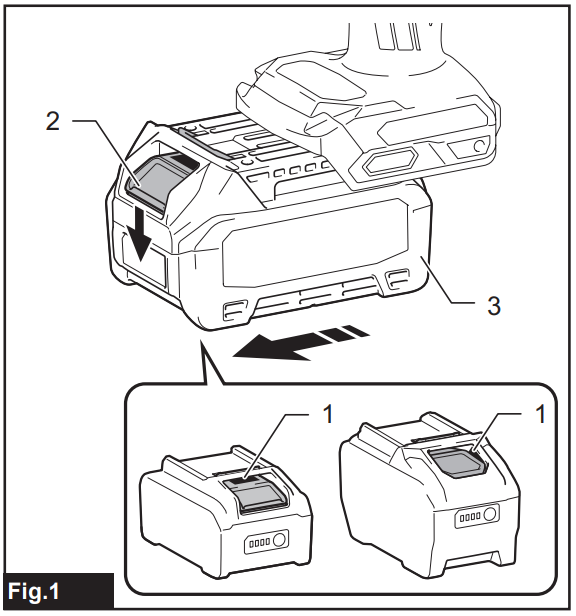
Indicating the remaining battery capacity
Press the check button on the battery cartridge to indicate the remaining battery capacity. The indicator lamps light up for a few seconds. ► Fig.2: 1. Indicator lamps 2. Check button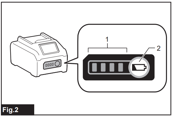
Tool/battery Protection System
The tool is equipped with a tool/battery protection system. This system automatically cuts off power to the
motor to extend the tool and battery life. The tool will automatically stop during operation if the tool or battery is placed under one of the following conditions:
Overload Protection
When the battery is operated in a manner that causes it to draw an abnormally high current, the tool automatically stops without any indication. In this situation, turn the tool off and stop the application that caused the tool to become overloaded. Then turn the tool on to restart.
Overdischarge Protection
When the battery capacity is not enough, the tool stops automatically. In this case, remove the battery from the tool and charge the battery.
Protections against other The protection system is also designed for other causes that could damage the tool and allows the tool to stop automatically. Take all the following steps to clear the causes when the tool has been brought to a temporary halt or stops in operation.
- Make sure that all switch(es) is/are in the off position, and then turn the tool on again to restart.
- Charge the battery(ies) or replace it/them with h recharged battery(ies).
- Let the tool and battery(ies) cool down.
If no improvement can be found by restoring the protection system, then contact your local Makita Service Center.
Switch Action
To start the tool, simply pull the switch trigger. The speed is increased by increasing pressure on the switch trigger. Release the switch trigger to stop. ► Fig.3: 1. Switch trigger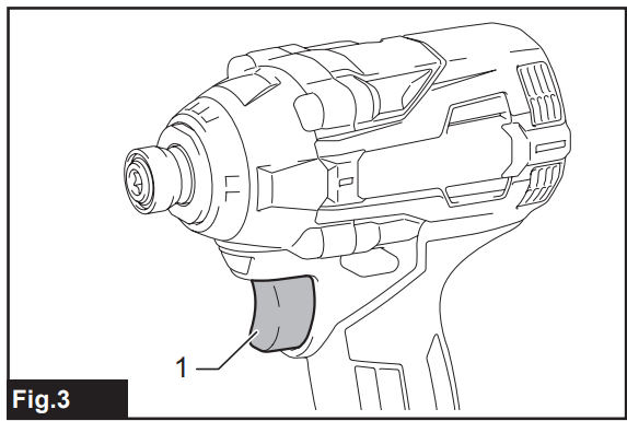
Reversing Switch Action
This tool has a reversing switch to change the direction of rotation. Depress the reversing switch lever from the A side for clockwise rotation or from the B side for counterclockwise rotation. When the reversing switch lever is in the neutral position, the switch trigger cannot be pulled. ► Fig.4: 1. Reversing switch lever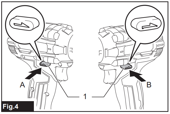
Electric Brake
This tool is equipped with an electric brake. If the tool consistently fails to quickly stop after the switch trigger is released, have the tool serviced at a Makita service center.
Lighting up the Front Lamp
Fig.5: 1. Front lamp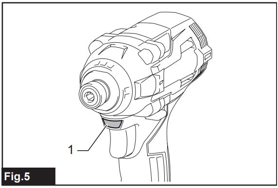
Pull the switch trigger to turn on the front lamp. To turn off, release the switch trigger. The front lamp goes out approximately 10 seconds after releasing the switch trigger. To disable the front lamp, turn off the lamp status. To turn off the lamp status, first pull and release the switch trigger. Within 10 seconds after releasing the switch trigger, press and hold the button for a few seconds. When the lamp status is off, the front lamp will not turn on even if the trigger is pulled. To turn on the lamp status again, press and hold the button for a few seconds. ► Fig.6: 1. Button 2. Switch panel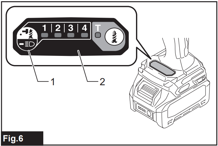
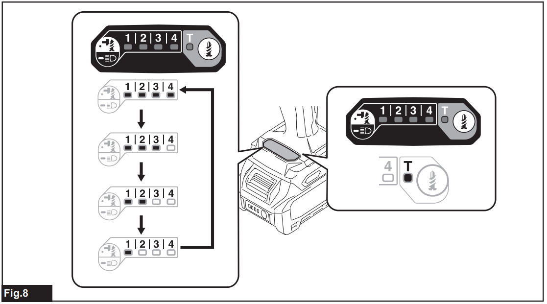
Changing the Impact Force
You can change the impact force in five steps: 4 (max), 3 (hard), 2 (medium), 1 (soft), and T mode.
This allows a tightening suitable for the work. “T” is a special mode for fastening self-drilling screws. This mode helps to prevent the screws from over-tightening. It also accomplishes quick operation and a good finish at the same time. The tool drives a screw with high-speed rotation and stops soon after the tool starts to impact. The level of impact force changes every time you press the button or button. You can change the impact force within approximately one minute after releasing the switch trigger.
Changing the Application Mode
What’s the application mode?
The application mode is the variation of the driving rotation and impact, which are already preset in the tool. By choosing a suitable application mode depending on the work, you can accomplish quicker work and/or a more beautiful finish.
This tool features the following application modes:
Impact force
- 4 (Max)
- 3 (Hard)
- 2 (Medium)
- 1 (Soft)
- T mode
The application mode can be changed by the button or button. ► Fig.7: 1. Button 2. Button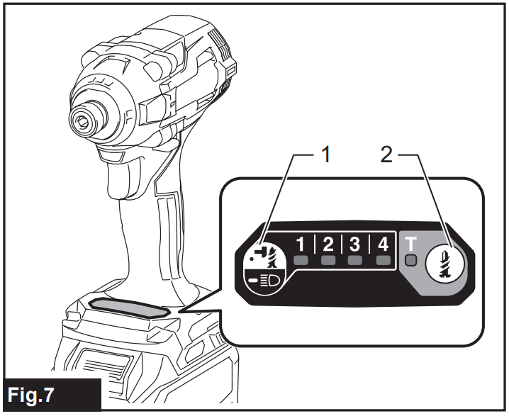
| Application mode (Impact force grade displayed on panel) | Maximum blows | Purpose | Example of application |
| 4 (Max) | 3,900 min-1 (/min) | Tightening with the maximum force and speed. | Driving screwsintoo the underwork materials, tightening long screws or bolts. |
| 3 (Hard) | 3,600 min-1 (/min) | Tightening with less force and speed than Max mode (easier to control than Max mode). | Driving screws into underworked materials, tightening bolts. |
| 2 (Medium) | 3,100 min-1 (/min) | Tightening when a good finish is needed. | Driving screws into finishing boards o oards. |
| 1 (Soft) | 1,900 min-1 (/min) | Tightening with less force to avoid screw thread breakage. | Tightening sash screws or small screws such as M6. |
| T mode * | (The tool stops rotating soon after impact starts.) | Driving self-drilling screws into a thin metal plate with a good finish. | Tightening self-drilling screws. |
The lamp is on. When the tool rotates counterclockwise, the impact per minute is the same as in 4 (max) mode, 3,900 min-1 (/ min).
Assembly
Installing or removing a driver bit/socket bit
Use only the driver bit/socket bit that has the inserting portions shown in the figure. Do not use any other driver bit/ socket bit.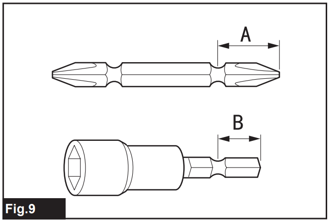
For a tool with a shallow driver bit hole
| A=12mm B=9mm | Use only these types of driver bits. Follow procedure 1. (Note) Bit-piece is not necessary. |
For a tool with a deep driver bit hole
| A=17mm B=14mm | To install these types of driver bits, follow procedure 1. |
| A=12mm B=9mm | To install these types of driver bits, follow procedure 2. (Note) Bit-piece is necessary for installing the bit. |
Procedure 1
For a tool with a one-touch type sleeve, to install the driver bit, insert the driver bit into the sleeve as far as it will go.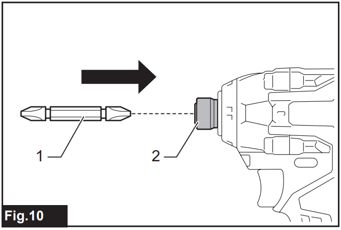
Procedure 2
In addition to Procedure 1, insert the bit-piece into the sleeve with its pointed end facing in.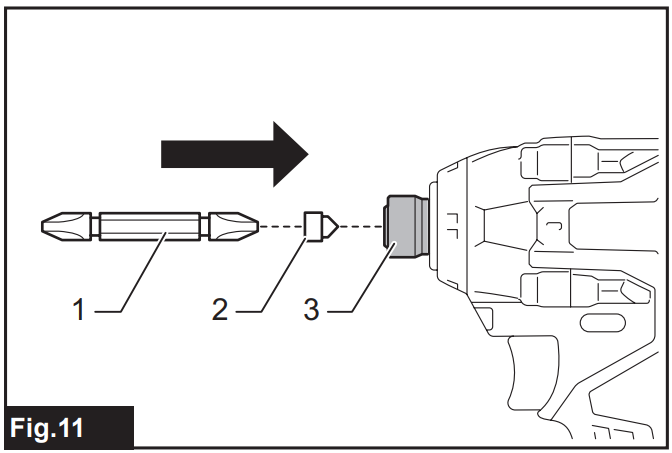
To remove the driver bit, pull the sleeve in the direction of the arrow and pull the driver bit out.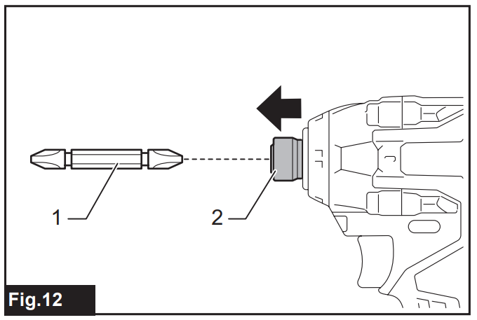
Installing hook
The hook is convenient for temporarily hanging the tool. This can be installed on either side of the tool. To install the hook, insert it into a groove in the tool housing on either side and then secure it with a screw. To remove, loosen the screw and then take it out.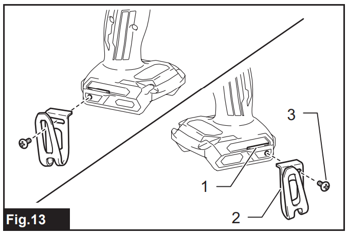
Using Hole
Use the hanging hole at the bottom rear of the tool to hang the tool on a wall using a hanging cord or similar strings.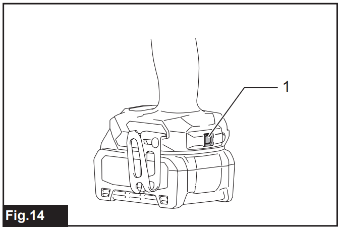
Operation
The proper fastening torque may differ depending upon the kind or size of the screw/bolt, the material of the workpiece to be fastened, etc.
The relation between fastening torque and fastening time for a standard bolt (when the impact force is 4)
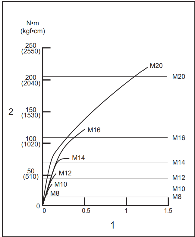
1. Fastening time (seconds) 2. Fastening torque: The relation between fastening torque and fastening time for a high tensile bolt (when the impact force is 4)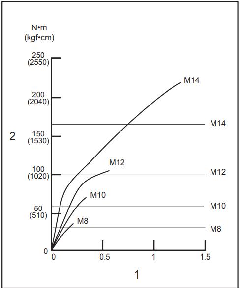
The fastening torque is affected by a wide variety of factors, including the following. After fastening, always check the torque with a torque wrench.
- When the battery cartridge is discharged almost completely, the voltage will drop, and the fastening torque will be reduced.
- Driver bit or socket bit. Failure to use the correct size driver bit or socket bit will cause a reduction in the fastening torque.
Bolt
- Even though the torque coefficient and the class of bolt are the same, the proper fastening torque will differ according to the diameter of the bolt.
- Even though the diameters of bolts are the same, the proper fastening torque will differ according to the torque coefficient, the class of bolt, and the bolt length.
- The manner of holding the tool or the material of the driving position to be fastened will affect the torque.
- Operating the tool at low speed will cause a reduction in the fastening torque.
Specifications
| Model: | TD004G | |
| Fastening capacities | Machine screw | M4 – M8 |
| Standard bolt | M5 – M20 | |
| High tensile bolt | M5 – M14 | |
| No load speed (RPM) | 4 (Max impact mode) | 0 – 3,900 min-1 |
| 3 (Hard impact mode) | 0 – 3,000 min-1 | |
| 2 (Medium impact mode) | 0 – 2,100 min-1 | |
| 1 (Soft impact mode) | 0 – 1,200 min-1 | |
| T mode | 0 – 2,400 min-1 | |
| Impacts per minute | 4 (Max impact mode) | 0 – 3,900 min-1 |
| 3 (Hard impact mode) | 0 – 3,600 min-1 | |
| 2 (Medium impact mode) | 0 – 3,100 min-1 | |
| 1 (Soft impact mode) | 0 – 1,900 min-1 | |
| T mode | – | |
| Rated voltage | D.C. 36 V – 40 V max | |
| Overall length | 136 mm | |
| Net weight | 1.8 – 3.1 kg |
Optional Accessories
If you need any assistance for more details regarding these accessories, ask your local Makita Service.
Center.
- Driver bits
- Socket bits
- Bit-piece
- Hook
- Tool hanger
- Plastic carrying case
- Makita genuine battery and charger
Customer Service
- Website: https://www.makitauk.com/
- Ph: 1-800-462-5482
FAQs
Q: What is the Makita M8103 Hammer Drill used for?
The Makita M8103 is a corded hammer drill that may be used to drill into concrete, masonry, metal, and wood. It delivers more impact force for hard materials while retaining accuracy for lighter tasks by combining rotary and hammering action.
Q: What is the drill’s power rating?
With a 710W motor and 230V AC power, this model provides powerful torque and fast performance for both residential and commercial use.
Q: How do I switch between drilling and hammering modes?
Utilise the mode selector lever located on the tool’s side or top. To avoid damaging the gear, always make sure the drill is turned off before changing modes.
Q: Is this a variable-speed drill?
Indeed. With the M8103’s variable speed trigger, you may adjust the drilling speed according to bit size and material hardness for increased accuracy.
Q: Does it have a reverse function?
Indeed, the forward/reverse lever makes it simple to back out drill bits or remove screws. This is particularly helpful for screw-driving or threading applications.
Q: Can it be used as a screwdriver?
The M8103 is mostly a drill, albeit it can drive screws. A specialised screwdriver or impact driver is advised for regular screw driving in order to improve torque control.
Q: What kind of chuck does it have?
During heavy-duty drilling, the M8103’s 13 mm keyed chuck ensures a firm hold on drill bits and better torque transfer.
Q: How do I use the depth gauge?
Adjust the depth gauge rod to the appropriate drilling depth by inserting it into the side handle. For precise work, this aids in achieving a constant hole depth.