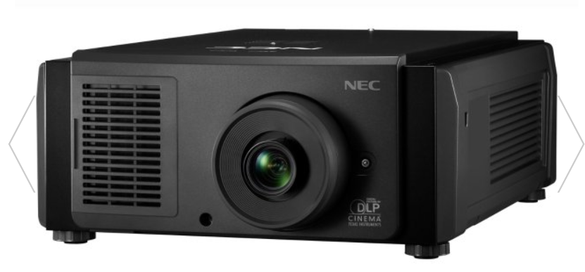
NEC NC1503L DLP Cinema Projector
Important Information
Precautions: Please read this manual carefully before using your NP-NC1503L and keep the manual handy for future reference. The NP-NC1503L is called the “projector”, and the IMB (integrated media server) is called the “media block” or “IMB” in this manual.
- DLP (Digital Light Processing), DLP Cinema, and DLP Cinema logo are trademarks of Texas Instruments.
- Microsoft and Windows are either registered trademarks or trademarks of Microsoft Corporation in the United States and/or other countries.
- Oracle and Java are registered trademarks of Oracle and/or its affiliates.
- Linux is a registered trademark of Linus Torvalds in the United States and/or other countries.
- Other product names and logos mentioned in the user’s manual may be the trademarks or registered trademarks of their respective holders.
- The display screens and illustrations shown in this manual may differ slightly from the actual ones.
- GPL/LGPL Software Licenses
- The product includes software licensed under the GNU
- General Public License (GPL), GNU Lesser General Public License (LGPL), and others.
- For more information on each software, see “readme.pdf” inside the “about GPL&LGPL” folder on the website.
Laser Safety Caution
This product is classified as Class 1 of IEC 60825-1, Third edition 2014. This product is classified as RG3 of IEC/EN 62471-5 First edition 2015.
- This product complies with performance standards for laser products under 21 CFR Part 1040, except with respect to those characteristics authorized by Variance Number 2015-V-3435, effective on April 7, 2016. Obey the laws and regulations of your country in relation to the installation and management of the device.
- Outline of laser emitted from the built-in light module: Wavelength: Red 635-647 nm, Blue 449-471 nm, Maximum power: Red 43 W, Blue 636 W
- No direct exposure to the beam shall be permitted, RG3 IEC/EN 62471-5:2015. Operators shall control access to the beam within the hazard distance or install the product at a height that will prevent spectators’ eyes from being in the hazard distance.
- Do not look into the lens while the projector is on. Serious damage to your eyes could result.
- Do not look at the operating light source. Eye injury may result.
- Not for household use. (for USA)
- This projector must be installed high enough to provide clearance for people who may walk beneath the beam path or hazard distance. (for USA)
- Direct exposure of human eyes to the beam is prohibited.
- The following graphic symbol,, indicating that looking into the projector is prohibited, is displayed on the projector cabinet.
- Do not allow yourself to look into the projector beam at any distance from the projector. An adult should supervise the children to prevent exposure risks.
- Check that there is no one looking at the lens when using the remote control for starting the projector.
- Do not look at the projected light using optical devices (binoculars, telescopes, magnifying glasses, reflectors, etc). Doing so could result in vision impairment.
- When performing the lens shift adjustment, make sure that you are behind or beside the projector. Doing so from the front of the projector may cause intense light to enter your eyes, resulting in damage to them.
- [WARNING: MOUNT ABOVE THE HEADS OF CHILDREN.] The use of a ceiling mount is recommended with this product to place it above the eyes of children.
- This projector, which is an RG3 product, is for business use and must be installed in a location where safety is assured. For this reason, installation of the projector and mounting and removal of the lens unit must be performed by professional service personnel. To do the work, be sure to consult your dealer. NEVER install the projector by end users. Doing so may cause visual impairment and other injuries.
- Keep any items, such as a magnifying glass, out of the light path of the projector. The light being projected from the lens is extensive; any kind of abnormal objects that can redirect light coming out of the lens can cause unpredictable outcomes, such as fire or injury to the eyes.
- When turning on the projector, ensure that nobody is facing towards the lens in the path of the light emitted from the laser.
What’s in the Box
Features
- DLP Cinema® projector Complies with the strict projection standards defined by the Digital Cinema Initiatives (DCI) industry group in the United States using leading imaging technology. It also supports 3D projection and high frame rates (HFR).
- Employs a long-life laser light source. The projector employs a newly developed laser light source offering excellent reliability and redundancy. Since the laser light source has a long life, this delivers low-cost operation by removing the need for maintenance, such as replacing and adjusting the light module over extended periods of time. Furthermore, it reduces the risk of the light source suddenly shutting off and leaving a black screen.
- Delivers reduced installation space and increased freedom through a more compact and lightweight body The use of a 0.69″ DLP cinema chip together with integration of the light module into the projector main unit both delivers a reduced installation area as well as improving the degree of freedom of installation, such as removing the need to connect to external ventilation ducting and supporting both pedestal-mounted and ceiling-suspended installation. A wide variety of optional lenses (sold separately) is also available for the projector in order to support a wide variety of installation methods (a lens is not mounted when the projector is shipped from the factory).
- Equipped with easy-to-use functions
- Lens memory function and light memory function that can be operated with one touch.
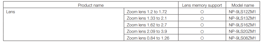
The projector is equipped with a lens memory function that can save the zoom position and shift position of the lens and a light memory function that can save the brightness setting separately for each input signal. This makes it possible to project using preconfigured settings simply by selecting the signal when projecting multiple different input signals, each with a different screen size and brightness settings (Refer to “6-9. Related products list” (page 78) for details on the lenses that support the lens memory function). - Built-in automatic adjustment function that makes the brightness and color of the light source uniform. Degradation of brightness and variations in color that occur as the light source is used for longer periods of time are kept to a minimum (the period over which variations in brightness can be limited varies depending on the brightness setting).
- Frequently used titles can be registered in preset buttons. The projector has been equipped with 8 preset buttons that make it easy to selecta registered title (input signal). To this projector, 100 titles at most can be registered (input signal registration). Among the registered titles, any 16 titles can be assigned to the preset buttons.
- You can operate and configure the projector via a network from a PC You can operate and configure the projector via a network from a PC by using the separately supplied software Digital Cinema Communicator (DCC) V2.
- Lens memory function and light memory function that can be operated with one touch.
Advanced Dust Protection
A dust control shield is arranged between each DMD chip of R, G, and B, and the spectroscopic/condenser prism. It prevents dust and dirt in the air, and oily particles in smoke associated with event halls from coming into contact with the face of the DMD and causing operating problems.
- Reduced running costs thanks to the use of metal filters. The filters are made of metal, so they can be used repeatedly and do not have to be replaced when performing periodic cleaning. This not only reduces running costs, but also contributes to preserving the environment since spent filters are not discarded.
What’s in the Box
Projector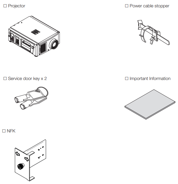
Names of the Projector Parts
Front of the projector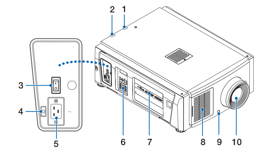
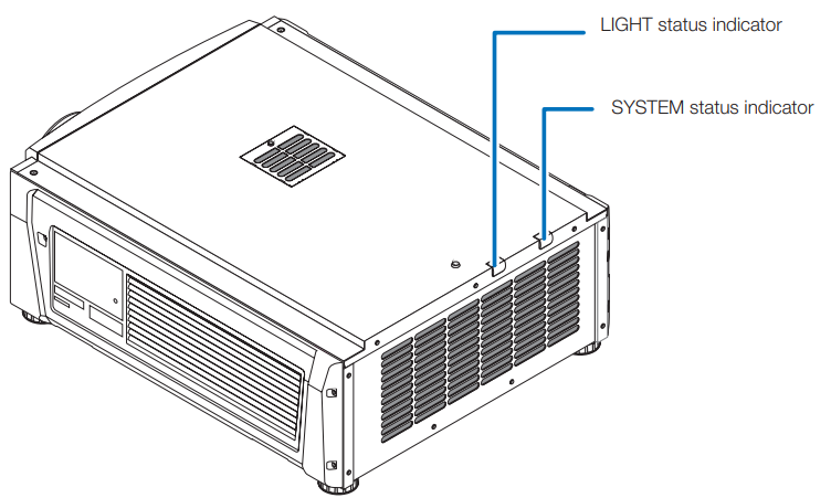
- LIGHT status indicator: Displays the status of the light source. The indicators turn on when the light source is on and turn off when the light source is off (See page 61).
- SYSTEM status indicator: These indicate the status of the projector. When the projector is operating normally, these lights/blink in green or orange. When an error occurs, they light/blink in red. When an error occurs, check the contents of the display on the LCD screen. (See page 61)
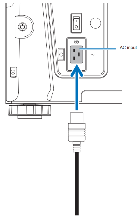
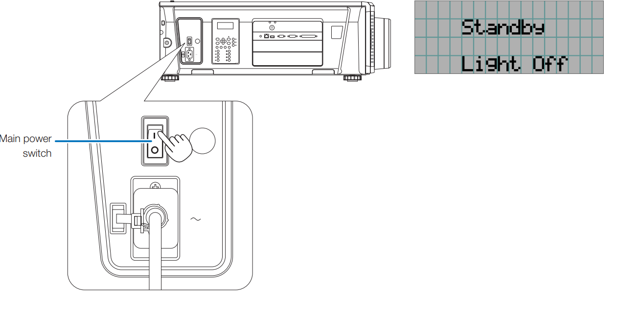
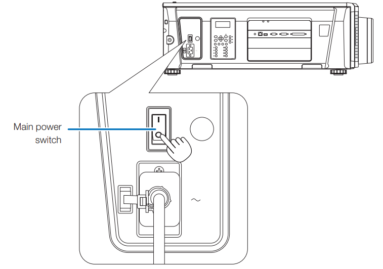
- Main power switch. While AC power is being supplied, set the main power switch to the ON position (1), then your projector will enter a standby state.
- The power cable stopper prevents the power plug from falling out of the projector.
- AC input connects to the AC power cable. The AC power cable is not an accessory. Consult with your dealer/distributor about the AC power cable.
- On the control panel, power to your projector is turned on or off, titles are selected, and various adjustments are made to the projected screen. (See page 19)
- Connection terminals.. Various image signal cables are to be connected here. (See page 18) You can expand signal input terminals by installing the optional board. Contact your dealer/distributor for more information on separately sold optional products.
- Air inlet: The air inlet for cooling inside the projector. Do not cover. An air filter is attached over the air inlet to prevent dust.
- Remote interlock connector (inside front of projector). This port is for safely using the laser in this device. It is used to externally control the laser illumination in the projector. Consult with your dealer/distributor about using this.
- Lens (optional) Images are projected from the lens. Request your dealer/distributor to install or replace the lens.
Rear of the projector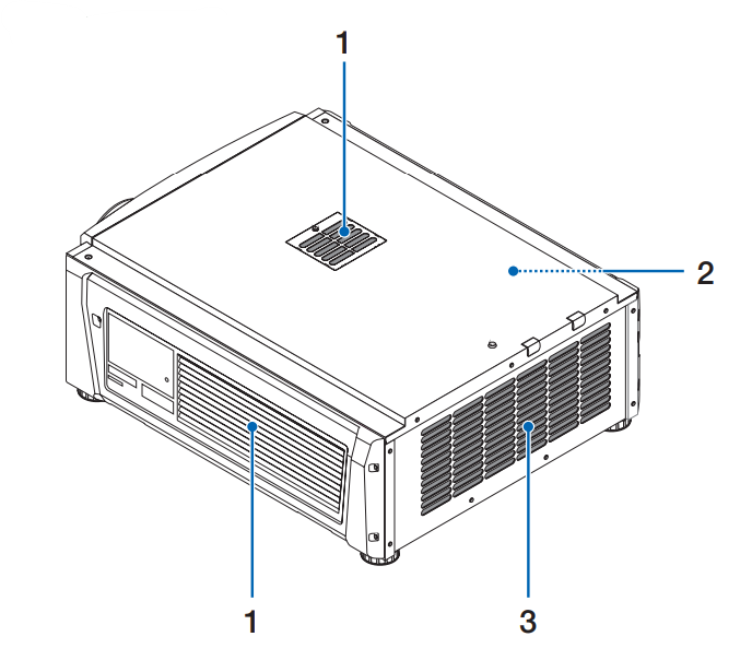
- Air inlet: The air inlet for cooling inside the projector. Do not cover. Air filters are attached over the air inlet to prevent dust.
- Buzzer (inside rear of projector) The buzzer rings when the power is turned on or an error has occurred.
- Air outlet: The air outlet to exhaust heat inside the projector. Do not cover.
Bottom of the projector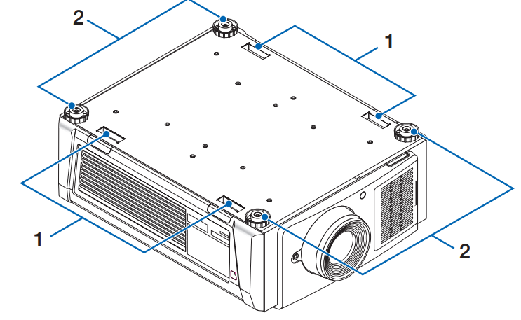
- Handle (4 locations): Handles for moving the projector.
- Level adjusters (in 4 positions). In the ordinary installation, you can adjust the projector inclination at 4 positions.
Connection terminals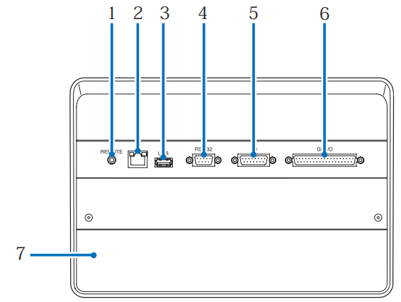
- Service terminal (REMOTE) (Stereo mini). This terminal is used for service purposes only.
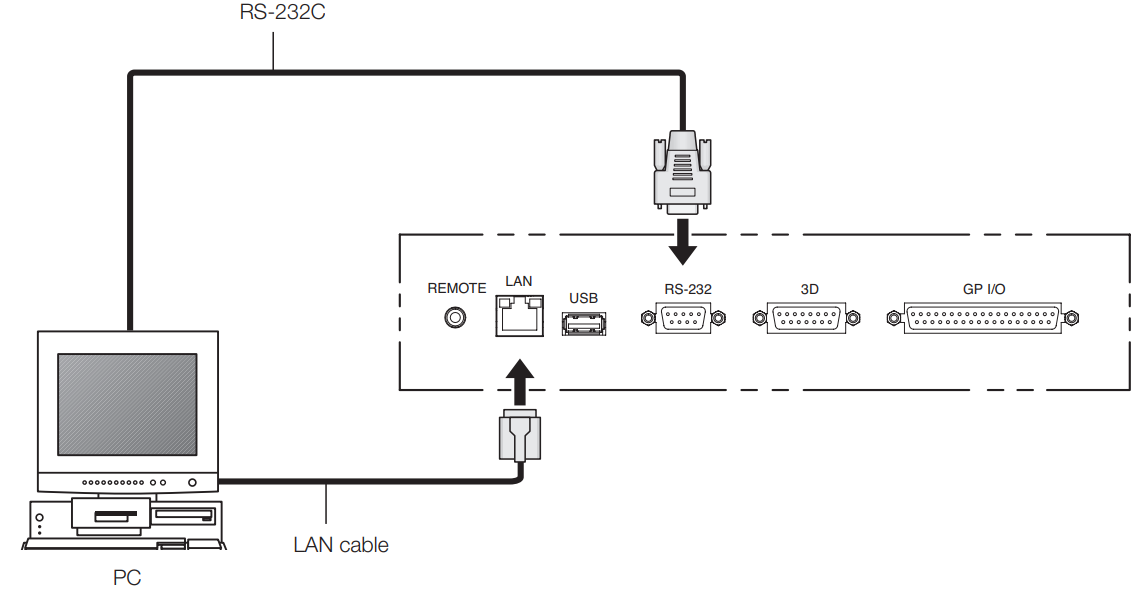
- Ethernet port (LAN) (RJ-45) The port for interfacing with an image signal server or controlling the projector from a PC via a network. Connect the projector and the PC with a commercially available Ethernet cable (10/100Base-T).
- USB port (USB) (type A) The port for the projector maintenance.
- PC control terminal (RS-232) (D-sub 9P) The terminal for operating the projector from a PC via an RS-232C or for service personnel to set data for the projector. Connect the projector and the PC with a commercially available RS-232C straight cable.
- 3D terminal (3D) (D-sub 15P) The terminal for connecting a 3D image system to the projector. (See page 77)
- External control terminal (GP I/O) (D-sub 37P) The terminal for externally controlling the projector or connecting a 3D image system to the projector. (See page 72)
- The slot is used for an image media block (IMB). Contact your dealer/distributor for an installation of IMB. Refer to the IMB instruction manual for details on IMB.
Control panel
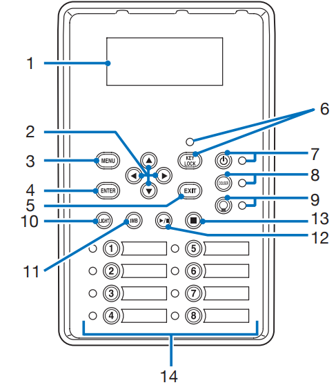
- The LCD screen displays menus and settings for the projector operations.
- (UP/DOWN/LEFT/RIGHT) Press these buttons to select a menu item while a menu is displayed.
- MENU button Press this button to display the menu for various settings and adjustments. (See page 43)
- ENTER button Press this button to select the menu item.
- EXIT button Press this button to return to the previous menu item.
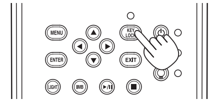
- KEY LOCK button: Press this button to lock (KEY LOCK) the buttons on the control panel. Buttons on the control panel do not function while KEY LOCK is on. Pressing the KEY LOCK button for one second or longer while KEY LOCK is off locks the buttons. Pressing the KEY LOCK button for one second or longer while KEY LOCK is on unlocks the buttons. (See page 35)
- button (POWER button) Press this button for more than three seconds to turn on or off (standby) the projector. (See page 60) In order to start up the projector, turn on the main power switch for the projector to set the projector in the standby state. (See page 28)
- DOUSER button Press this button to open and close the douser. (See page 60)
- button (LIGHT ON/OFF button) Press this button for five seconds or longer to turn on or off the light source while the projector is on. (See page 36)
- LIGHT button: Press this button to display the light source adjustment menu. (See page 34)
- IMB button (planned to be supported in a future update). This button is operable when the media block is installed in the projector. Press this button to display the operation menu of the media block.
- Play/pause button (planned to be supported in a future update). This button is operable when the media block is installed in the projector. Press this button to play or pause the image contents.
- Stop button (planned to be supported in a future update). This button is operable when the media block is installed in the projector. Press this button to stop playing the image contents.
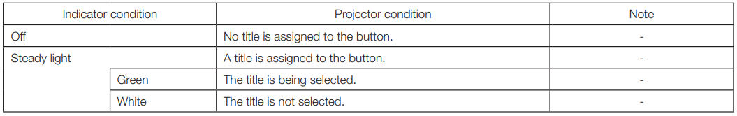
- Preset buttons: Press the preset button to select a title (input signal) assigned to each button. Up to 100 titles (input signals) can be registered to this projector, and any 16 titles from them can be assigned to the preset button. Please request your ealer to register and change the titles of the buttons as required. The preset button indicators show their assigned title or selection status. (See page 59)
Installation and Connection
Steps for setting up and connecting
Use the following steps for setting up your projector:
- Step 1 Setup the screen and projector. (Contact your dealer to carry out the setup.)
- Step 2: Connect the power cable to the projector. (See page 22)
- Step 33: 3 Connect cables to the image input terminals. (See page 26) Connect cables to the various control terminals. (See page 26)
Connecting the Power Cable
The power cable is not included with the projector. Use a power cable that meets the standards and power supply voltage of the country where you are using the projector. Ask your dealer for the power cable to select and purchase.
- Connect the AC power supply cable. Connect the AC power supply cable to the projecto.r
- Connect the power plug to the electrical outlet. This completes the connection of the AC power supply cable.
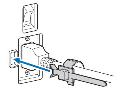
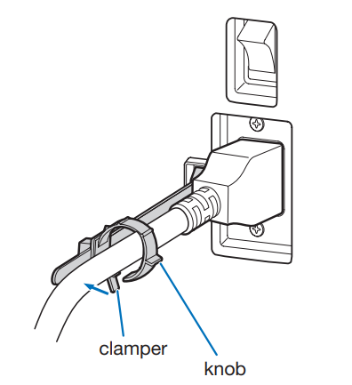
Attaching the power cable stopper
- Insert the end of the band of the power cable stopper into the slot next to the AC IN on the terminal panel.
- Use the power cable stopper to clamp the power cable. Push the clamp to lock it.
- Slide the clamp to the hilt of the power cable.

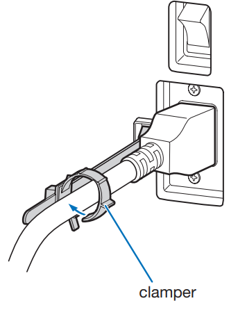
This completes the attachment of the power cable stopper.
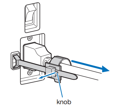
- Push the clamp of the power cable stopper to unclasp it. knob
- Push the power cable clamp to open it wide enough to pull out the power cable.
Connecting the image input terminals
Refer to the instruction manual of the IMB for details on connecting the video input ports with external equipment.
Connecting the various control terminals
For control, your projector comes with such ports as the PC control terminal and the Ethernet port (RJ-45).
- PC control terminal (RS-232) ——— Use this terminal when controlling the projector in a serial connection from a PC.
- LAN port (LAN)————————- Use this port when controlling the projector in a LAN connection from a PC.
Projection of Images (Basic Operation)
Steps of projecting images
- Step 1: Turn on the power to the projector. (See page 28)
- Step 2: 2: Select the title of the input signal. (See page 30)
- Step 3:Adjust the position and size of the projected screen. (See page 31)
- Step 4: Turn off the power to the projector. (See page 37)
Preparation:
- Connect the power cable to the projector (see page 22).
- Supply AC power to the projector.
- Remove the lens cap.
- Turn on the main power switch on the side of the projector. A buzzer will ring on the projector. The POWER button indicator will blink green, and the SYSTEM status indicator will light orange (standby state). The key lock becomes automatically on if no control panel operation takes place in the standby state for 30 seconds by default. Buttons on the control panel do not function while KEY LOCK is on. (See page 35)
- If KEY LOCK is on, press the KEY LOCK button for one second or longer. The key lock turns off. The KEY LOCK button indicator turns off, and buttons on the control panel become operable. (See page 35)
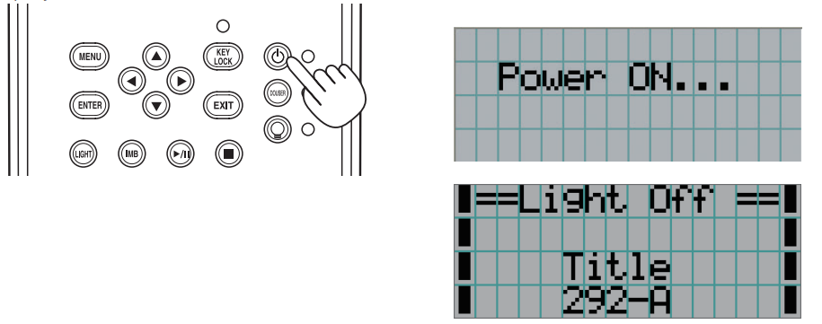
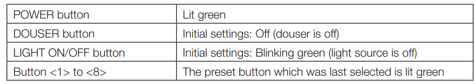
- Press the POWER button on the control panel of your projector for three seconds or longer. Your projector is turned on. When the startup of the projector completes, the status of the POWER button, DOUSER button, LIGHT ON/OFF button, and preset button (button <1> to <8>) changes as follows
- Press the LIGHT ON/OFF button on the control panel for three seconds or longer. The light source is turned on, and the screen glows light about 15 seconds later. The LIGHT ON/OFF button indicator blinks in cycles of 2 (and changes to a steady green light 90 seconds later). The douser is closed until the screen glows light (the DOUSER button indicator lights green). When the douser is open, the DOUSER button indicator turns off.
Selecting the title of the input signal
- Turn on the power to the image devices connected to the projector.
- Press the MENU button.
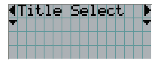
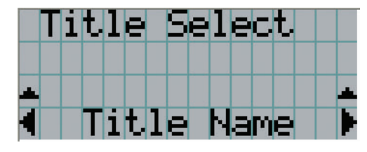
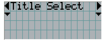
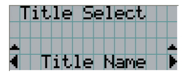
- Press the LEFT/RIGHT button to display “Title Select” on the LCD screen. At each press of the LEFT/RIGHT buttons, the display will cycle as “Title Select” ←→ “Configuration” ←→ “(Title Setup)” ←→ “Information.
- Press the DOWN button. The title of the input signal is displayed.
- When you have made a wrong selection, press the UP button. A return will be made to the previous menu.
- When you have made a wrong selection, press the UP button. A return will be made to the previous menu.
- Press the LEFT/RIGHT buttons to display “Title of Signal to be Projected” on the LCD screen.
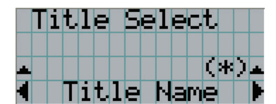
- Press the ENTER button. The title of the signal to be projected is selected.
- The (*) mark on the LCD indicates that this is the currently selected item.
- The (*) mark on the LCD indicates that this is the currently selected item.
Adjusting the position and the size of the projected screen
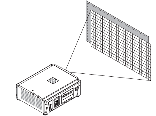
Displaying the test pattern
- Press the MENU button, or select a test pattern from preset buttons (button <1> to <8>). If you register the test patterns to the preset buttons (<1> to <8> buttons), select the test pattern according to “3-3. Selecting the title of input signal (See page 30)”.
- Press the LEFT/RIGHT button to display “Title Select” on the LCD screen.
- Press the DOWN button. The title of the input signal is displayed.
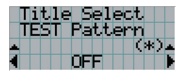
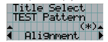
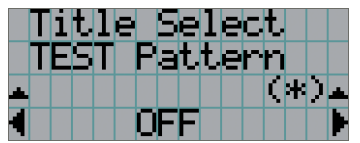
- Press the LEFT/RIGHT button to display “TEST Pattern” on the LCD screen.
- Press the DOWN button. The LCD screen enters the mode where you can select a test pattern.
- Press the LEFT/RIGHT button. This switches the test pattern name displayed on the LCD screen.
- Display on the LCD the name of the test pattern to be projected, then press the ENTER
button. The test pattern is displayed. To cancel the test pattern display, select the title of the signal to project or select the “OFF” test pattern. 3-4-2. Adjusting the position of the projected screen (Lens shift)
CAUTION
Perform the adjustment from behind or from the side of the projector. If adjustments are performed from the front, your eyes could be exposed to strong light and get injured.
- Press the MENU button.
- Press the LEFT/RIGHT button to display “Configuration” on the LCD screen.
- Press the DOWN button.
- Press the LEFT/RIGHT button to display “Lens Control” on the LCD screen.
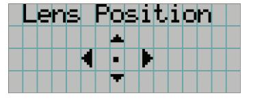
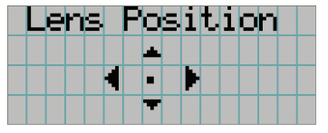
- Press the DOWN button. The screen (“Lens Position”) to adjust the position of the projected screen is displayed.
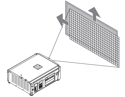
- Press the UP/DOWN/LEFT/RIGHT button. The position of the projected screen moves in the selected direction.
- Press the EXIT button when the adjustment is complete. The display will return to a menu one level above (where “Lens Control” is displayed).
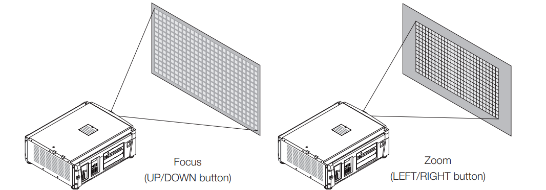
3-4-3. Adjustment of the size (zoom) and focus of the projected screen
- Press the MENU button.
- Press the LEFT/RIGHT button to display “Configuration” on the LCD screen.
- Press the DOWN button.
- Press the LEFT/RIGHT button to display “Lens Control” on the LCD screen.
- Press the DOWN button. The screen (“Lens Position”) to adjust the position of the projected screen is displayed.
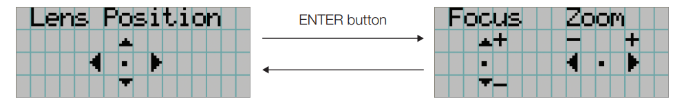
- Press the ENTER button. The screen to adjust the size and focus of the projected screen is displayed. Press the ENTER button to switch the display between “Lens Position” and “Focus Zoom” adjustments.
- Adjust the size and focus of the projected screen. Press the UP/DOWN button to adjust the focus. Press the LEFT/RIGHT button to adjust the size.
- Press the EXIT button when the adjustment is complete. The display will return to a menu one level above (where “Lens Control” is displayed).
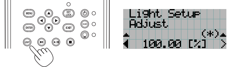
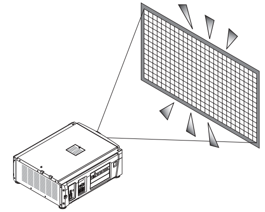
3-4-4. Adjusting the brightness of the projected screen (Light output)
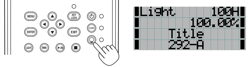
- Press the LIGHT button. The screen to adjust the light output is displayed.
- Press the LEFT/RIGHT button to adjust the light output. The specified adjustment value is applied.
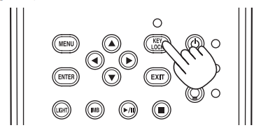
Preventing misoperations
Buttons on the control panel can be locked (KEY LOCK) to prevent misoperations. Buttons on the control panel do not function while KEY LOCK is on. The key lock must be off to operate these buttons.
KEY LOCK setting
- Press the KEY LOCK button on the control panel for one second or longer. The key lock becomes on. The KEY LOCK button indicator lights orange. When you press a button on the control panel of the projector while KEY LOCK is on, “Panel is Locked(KEY LOCK)” is displayed, and the button will not function. (See page 3
Turning the Y LOCK off
- Press the KEY LOCK button for one second or longer while KEY LOCK is on. The key lock turns off. The KEY LOCK button indicator turns off.
Turning on/off the light with the projector turned on
Turning off the light
- Press the LIGHT ON/OFF button on the control panel for three seconds or longer.
Turning on the light
- Press the LIGHT ON/OFF button on the control panel for three seconds or longer.
Turning your projector off
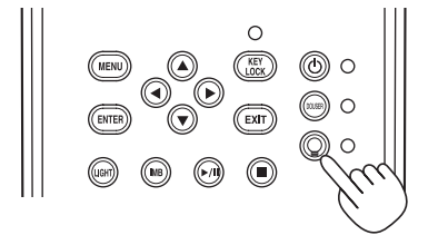
- Press the POWER button on the projector control panel for three seconds or longer. The light is turned off, the POWER button indicator blinks green, and the STATUS indicator blinks orange (cooling state). The fan will continue to rotate while cooling, and the amount of time remaining for cooling is displayed on the LCD screen. The cooling-off time is 90 seconds. When the cooling is finished, the POWER button indicator turns off and the status indicator lights orange (standby state). The key lock becomes automatically on if no control panel operation takes place in the standby state for 30 seconds by default. Buttons on the control panel do not function while KEY LOCK is on. (See page 35)
- Wait till the projector enters standby state before turning off the main power switch of the projector. The POWER button indicator is turned off, and the main power is turned off.f
Using Menus
Basic operation with adjustment menus. To adjust the projector, display the menu on the LCD screen of the projector control panel.
Screen display
The menu display screen is composed of a menu display field (the upper two lines) and a setting item display field (the bottom two lines).
The meanings of symbols in the menu display screen are outlined below. 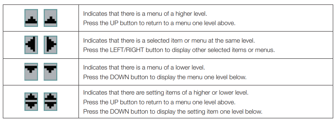 When not displaying menus, the following screen is normally displayed.
When in standby
When the projector is in a standby state (the main power switch is off), the following is displayed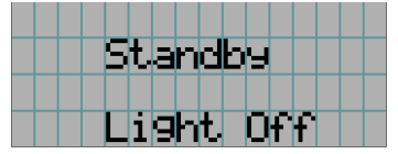
When power is turned on
When the power is turned on, the following is displayed.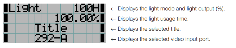
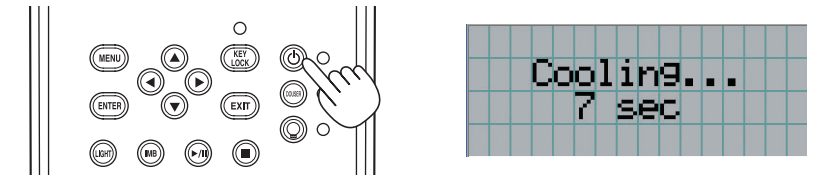
When the power is turned off
When you press the POWER button on the control panel of the projector for 3 or more seconds, the projector starts cooling. When cooling finishes, the projector enters the standby mode. The amount of time remaining for cooling is displayed as shown below during cooling.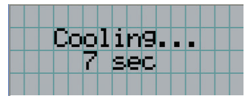
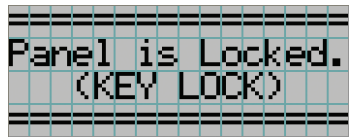
When a button is pressed while the key lock function is on
If a button on the control panel is pressed while the key lock function is on, the following is displayed, and the button will not function.
Operating menus
Preparation: Turn your projector on. (See page 28)
- Press the MENU button on the control panel of your projector. The menu is displayedonn the LCD screen.
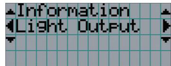
- Press the LEFT/RIGHT buttons to display “Information.” At each press of the LEFT/RIGHT buttons, the display will cycle as “Title Select” ←→ “Configuration” ←→ “(Title Setup)” ←→ “Information.”
- Press the DOWN button. The submenu “Light Output” of “Information” is displayed. The menu item can be selected by pressing the ENTER button instead of the DOWN button. To return to the previous state, press the UP button or the EXIT button.
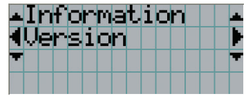
- Press the LEFT/RIGHT button to select the submenu “Version.” At each press of the LEFT/RIGHT button, the display will cycle as “Light” ←→ “Lens Type” ←→ “Preset Button” ←→ “Usage” ←→ “Error Code” ←→ “Version” ←→ “IP Address” ←→ “Setup Date” ←→ “Option Status.”
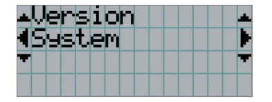
- Press the DOWN button. The submenu “System” is another rank lower than “Version” and is displayed.
- Press the DOWN button.
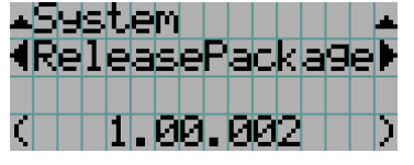
The submenu “BIOS” is another rank lower than “Model” is displayed. - Press the LEFT/RIGHT button to select the submenu “Release Package.”
At each press of the LEFT/RIGHT button, the display will cycle as “Model” ←→ “Serial No.” ←→ “Release Package” ←→ “Kernel” ←→ “U-Boot” ←→ “System Files” ←→ “Cinema Firmware” ←→ “Cinema Data” ←→ “ICP Firmware” ←→ “ICP ConfigFile” ←→ “FMT FPGA” ←→ “Secure Processor” ←→ “Slave BIOS” ←→ “Slave Firmware” ←→ “Opt MCUFirmware” ←→ “LD Interface” ←→ “LD Driver1” ←→ “LD Driver2” ←→ “LD Driver3” ←→ “LD Driver4” ←→ “LD Driver5” ←→ “LD Driver6” ←→ “Lens Firmware” and each version information is displayed. - Press the UP button several times. At each press of the UP button, the display will return to a menu one level above.


How to enter alphanumeric characters
Alphanumeric characters are entered for items, such as the log file of the specified period, which is written to USB memory. (See page 64) Characters can be entered by pressing the numeric buttons on the control panel of this projector.
Characters can be entered by pressing each button as shown in the following table.
- To delete a character during entry, press the DOWN button.
[Example of Entry]
To enter “XGA, for example, use the following procedure:
- Press the “8” button three times. V → W → X
- Press the RIGHT button.
- Press the “3” button. XG
- Press the RIGHT button.
- Press the “1” button. XGA
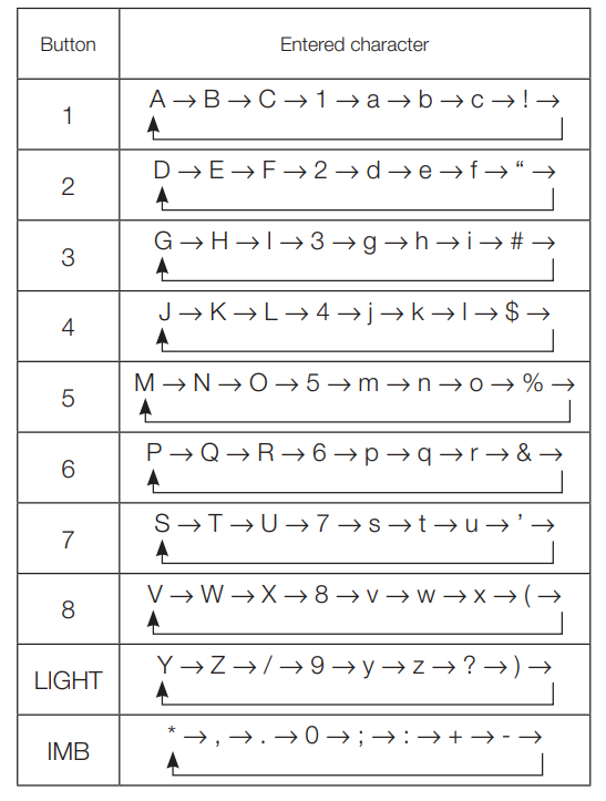
Table of adjustment menus
Menus in parentheses are menus for our service personnel. Normally, these menus cannot be used. 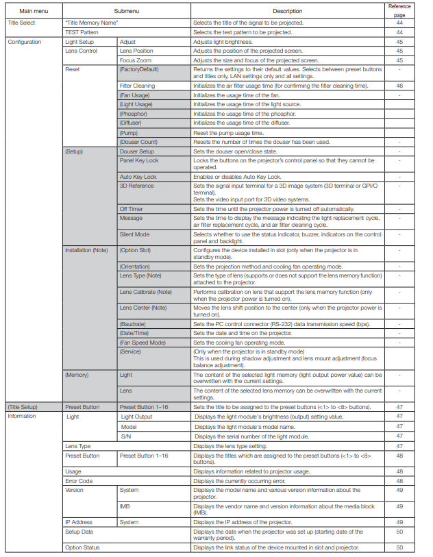
Title Select
Title select (Title Memory) Selects the title of the signal to be projected. You can register up to 100 titles. You can also assign registered titles to the preset buttons (<1> to <8> buttons) on the projector’s control panel and call them up directly using those buttons. Request your dealer/distributor for details on registering and changing titles.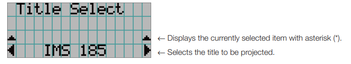
Test Pattern
Selects the test pattern to be projected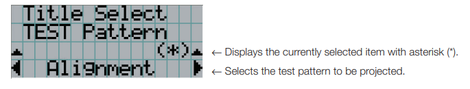
Configuration
Light Setup
Adjust
Adjusts the light output (brightness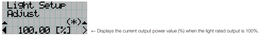
Lens Control
Adjust the position, size, and focus of the projected screen. Press the ENTER button to switch the display between “Lens Position” and “Focus Zoom” adjustments. Press the XIT button to return to a menu one level above.
Lens Position
Adjusts the position of the projected screen. The projected screen moves in the selected direction as you press the UP/DOWN/LEFT/RIGHT button.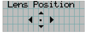
Focus Zoom
Adjusts the size (Zoom) and focus (Focus) of the projected screen. Press the UP/DOWN button to adjust the focus. Press the LEFT/RIGHT button to adjust the size of the projected screen.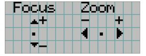
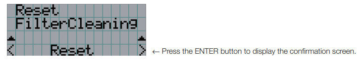
Reset
Filter Cleaning
Resets the air filter usage time (for confirming the filter cleaning time).
- Press the ENTER button, then the confirmation screen will appear.
- Select “Yes” in the confirmation screen, and then press the ENTER button to reset the filter usage time.
Title Setup
Sets the title to be assigned to the preset buttons (<1> to <8> buttons) (up to 16 titles). Request your dealer/distributor to perform the settings.
Information
Displays the hours of light use, the versioninformation,n, and error codes.
Light
Displays the light source information.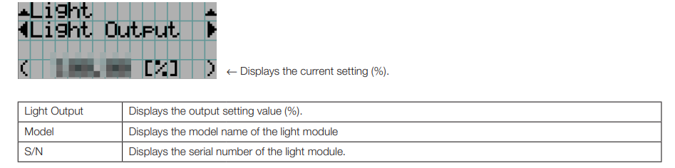
Lens Type
Displays the current lens type setting. The lens type setting is configured from “Lens Type” in the “Configuration” – “Installation” menu (page 45).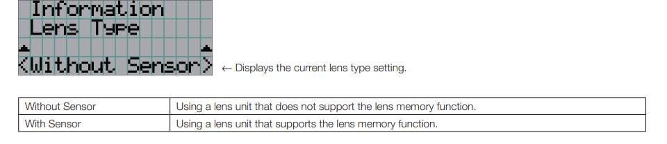
Preset Button
Sets the title to be assigned to the preset buttons (<1> to <8> buttons) on the projector’s control panel.
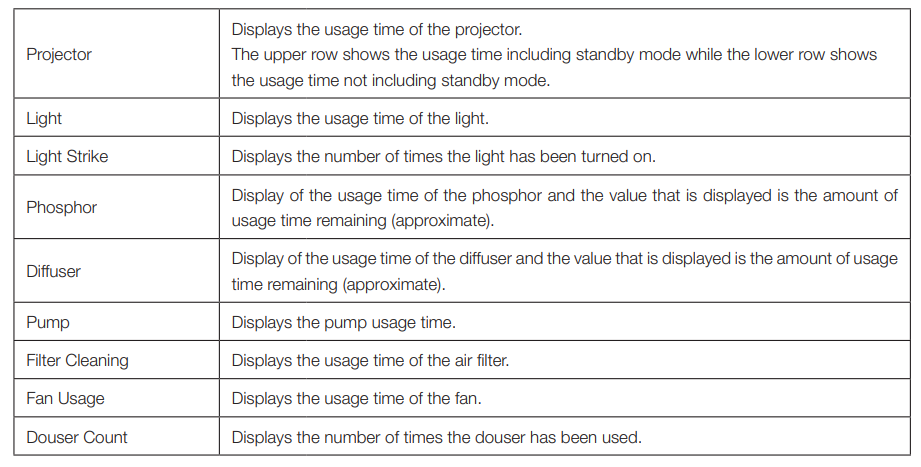
Usage
Displays information related to the projector usage, such as the usage time of the projector, light, air filters, and fan, and information about the light replacement cycle.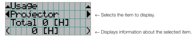
Error Code
Displays the error code when an error occurs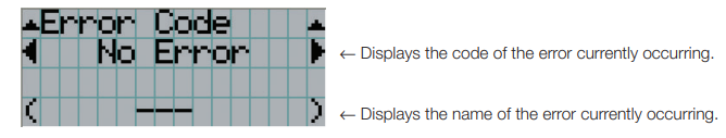
Version
Displays version information about the projector, optional boards, and IMB.
System
Displays the version information of the projector.
- Model
- Slave BIOS
- Serial No.
- Slave Firmware
- Release Package
- OpMCU Firmware
- Kernel
- LD Interface
- U-Boot
- LD Driver1
- System Files
- LD Driver2
- Cinema Firmware
- LD Driver3
- Cinema Data
- LD Driver4
- ICP Firmware
- D Driver5
- ICP ConfigFile
- LD Driver6
- FMT FPGA
- Lens Firmware
- Secure Processor
IMB
Displays the vendor name and version information about the media block (IMB). When the projector is in standby mode, the vendor name is blank,k and the version information displays “—”.
IP Address
Displays the IP address set in the projector
Setup Date
Displays the date when the projector was set up (starting date of the warranty period).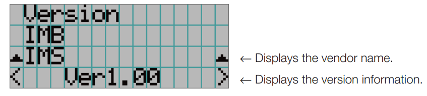
Option Status
Displays the link status of the device mounted in the slot on the projector. The device name is displayed in ( ) when the projector is in standby or when connection to the device cannot be confirmed.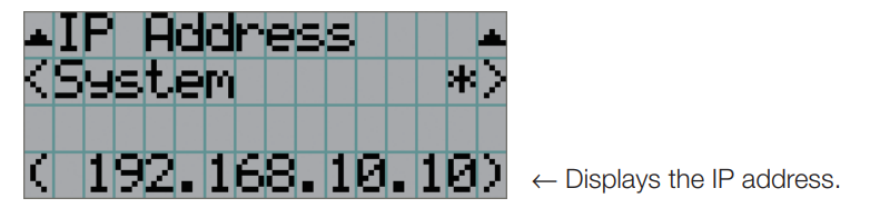
Maintenance of Your Projector
Cleaning the Cabinet
- Wipe with a dry, soft cloth without a nap. When the cabinet is excessively dirty, wipe with a well-wrung cloth after being dampened with a neutral detergent diluted with water, and then finish up with a dry cloth. When you use a chemical dust cloth, follow the instructions in the manual attached to it.
- Do not use a solvent, such as thinner or benzene. The coating may deteriorate or peel off.
- When removing dust from the ventilation opening, suck it off using an adapter with a brush on a vacuum cleaner. Never allow the cleaner without an adapter to come into direct contact or use a nozzleadapter in cleaning.
- Clean the ventilation opening at regular intervals. Dust, if allowed to accumulate there, may cause heating inside, which leads to functional trouble. The interval, which can vary with the location of your projector, is about 100 hours.
- Do not damage the cabinet by scratching it or allowing hard objects to hit it. This can scratch the projector.
- Consult your dealer/distributor about cleaning the inside of the projector.
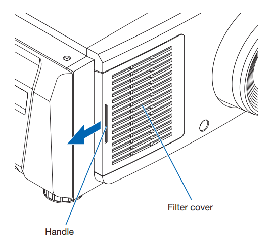
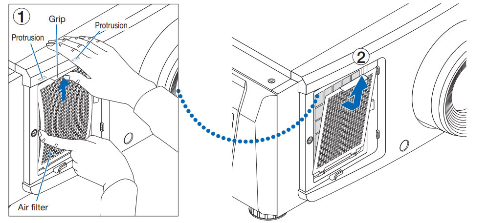
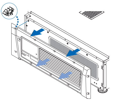
Cleaning the Air Filter (Front)
- Remove the filter cover. Place your finger on the handle, and slide the cover to the left to remove it.
- The filter cover cannot be removed, even if you pull it towards you
- The filter cover cannot be removed, even if you pull it towards you
- Remove the air filter.
- Push up the tip of the air filter grip strongly to bow the air filter slightly. Place your finger around the center of the air filter and pull it toward you until the top of the air filter is unhooked from the protrusions. Note: Be very careful not to bend the air filters when removing them.
- Pinch the top of the air filter and lift it upward to remove it.
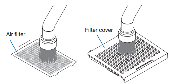
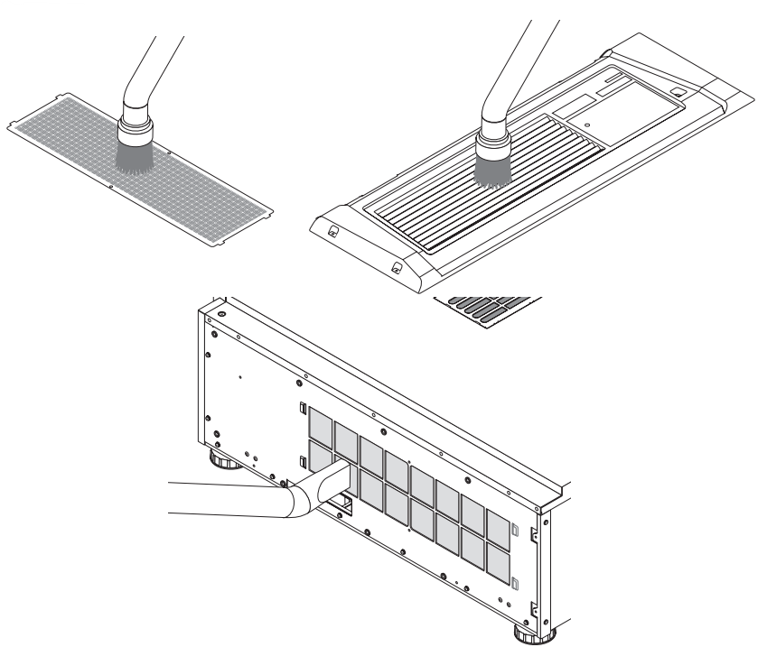
- Use a vacuum cleaner to remove the dust. Use a vacuum cleaner to suck up the dust from both sides of the air filter and the filter cover.
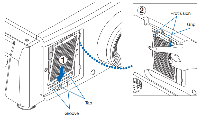
- Attach the air filter to the main unit.
- Insert the tabs of the air filter into the grooves on the main unit.
- Bow the center of the air filter by using your fingers and pinch the grip to insert the top of the air filter into the protrusions.
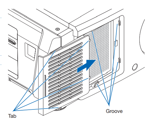
- Attach the filter cover to the main unit. There are tabs at the top and bottom, om and 2 locations on the right end of the filter cover. There are grooves at the top and bottom, to2 locations on the right end of the main unit. Slide the filter cover to the right and push it in while keeping the filter cover in close contact with the main unit. Each tab will go into the groove.
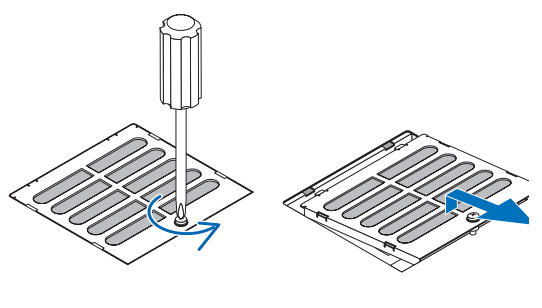
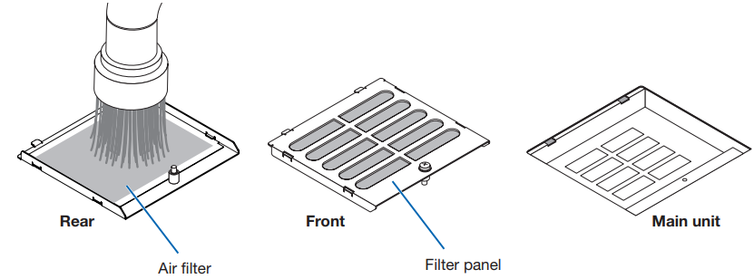
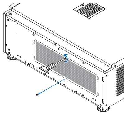
Cleaning the Air Filter (Top)
- Remove the filter panel. Turn the screw counterclockwise until it is loose, then turn up the filter panel slightly to remove it.
- The screw cannot be removed.
- The screw cannot be removed.
- Use a vacuum cleaner to remove the dust. Use a vacuum cleaner to suck up the dust on the front and rear of the filter panel (air filter) and the main unit. Caution: Do not remove the air filter. It may get bent and broken, thus becoming unusable.
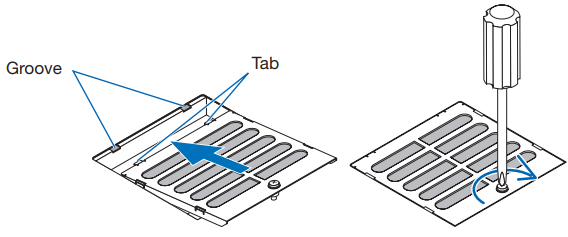
- Attach the filter panel to the main unit.
- Insert the tabs of the filter panel into the grooves on the main unit.
- Turn the screw clockwise to tighten it.
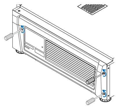
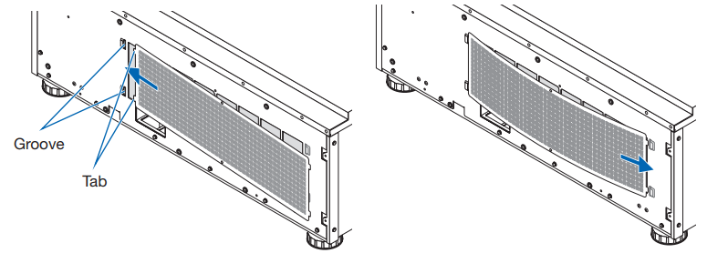
Cleaning the Air Filter (Side)
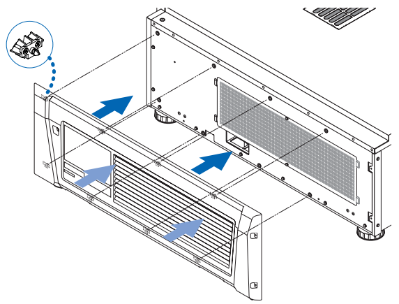
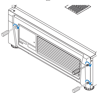
- Remove the side cover.
- Turn the screws at the 3 locations counterclockwise until they are loose.
- The screws cannot be removed.
- The screws cannot be removed.
- Pull the side cover towards you to remove it from the main unit.
- The side cover is fixed to the main unit with 8 tabs. Pull the side cover towards you to remove it. Remove in sequence, starting from the end.
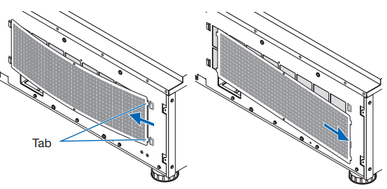
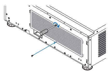
- Remove the air filter
- Turn the screws at the 2 locations counterclockwise to remove them.
- Bend the air filter slightly to detach the 2 tabs from the grooves on the main unit before removing the air filter. Caution: If you bend the metal filter too much with a strong force, it may bend and break, thus becoming unusable. Be very careful and bend it just a little.
- Use a vacuum cleaner to remove the dust. Use a vacuum cleaner to suck up the dust from both sides of the air filter and the front and back of the side cover. Air filters are also provided on the projector. They cannot be removed. Use a vacuum cleaner with a nozzle attachment to clean dust from the air filters.
- . Attach the air filter to the main unit.
- Insert the 2 tabs on the air filter into the 2 grooves on the main unit, bend the air filter slightly, and insert the tabs on the opposite side into the grooves on the main unit.
- Turn the 2 screws clockwise to secure the air filter to the main unit.
- Insert the 2 tabs on the air filter into the 2 grooves on the main unit, bend the air filter slightly, and insert the tabs on the opposite side into the grooves on the main unit.
- Turn the screws at the 2 locations counterclockwise to remove them.
- Attach the side cover
- Align the 8 tab positions on the main unit with the side cover and push them in sequentially, starting from the end.
- Turn the screws at the 3 locations clockwise to secure them. After completing cleaning the filters at three locations, select Configuration → Reset from the adjustments menu to reset Filter Cleaning. (see page 46)
- Align the 8 tab positions on the main unit with the side cover and push them in sequentially, starting from the end.
- The side cover is fixed to the main unit with 8 tabs. Pull the side cover towards you to remove it. Remove in sequence, starting from the end.
Troubleshooting
Before asking fora repair, please check your connection, settings, and operation. If the trouble cannot be corrected, please contact your dealer/distributor for instructions or repair.
Problems and where to check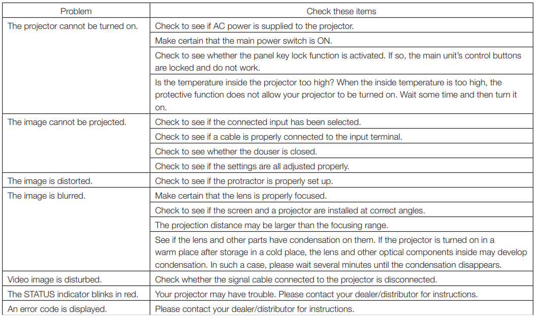
Indicator display list
See the descriptions below when the buttons on the control panel or the STATUS indicator on the rear of the projectare is lit or blinking. The projector also has a warning function that uses a buzzer.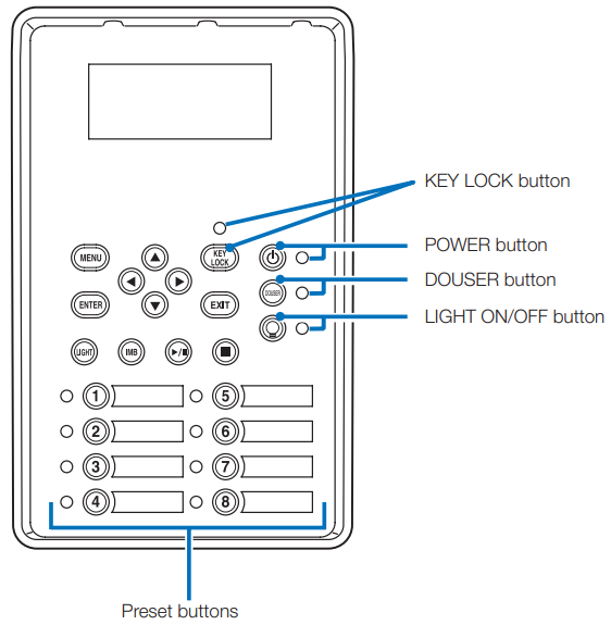
Preset buttons
POWER button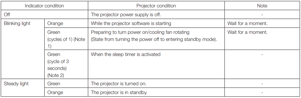
DOUSER button
LIGHT ON/OFF button
STATUS indicator
SYSTEM status indicator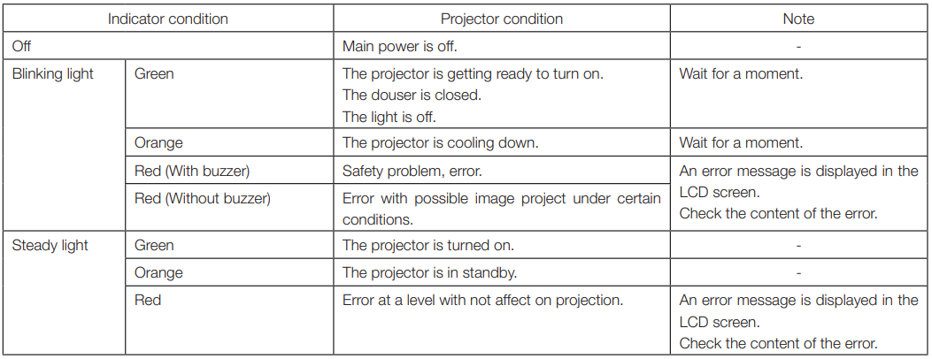
LIGHT status indicator
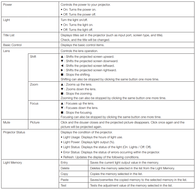
Operation using an HTTP browser
Overview
The use of HTTP server functions will allow control of the projector from a web browser. This device uses “JavaScript” and “Coo,kies” and the browser should be set to accept these functions. The setting method will vary depending on the version of the browser. Please refer to the help files and the other information provided in your software.
Preparation before use
Make network connections, set up the projector, and confirm that it is complete before engaging in browser operations. Operations with a browser that uses a proxy server may not be possible, depending on the type of proxy server and the method of setting it. Although the type of proxy server will be a factor, it is possible that items that have actually been set will not be displayed, depending on the effectiveness of the cache, and the contents set from a browser may not be reflected in operation. It is recommended that a proxy server not be used unless it is unavoidable.
Handling of the address for operation via a browser
Regarding the actual address that is entered for the address or entered to the URL column when operation of the projector is via a browser, the host name can be used as it is with the host name corresponding to the IP address of the projector has been registered in the domain name server by a network administrator, or the host name corresponding to the IP address of the projector has been set in the “HOSTS” file of the computer being used. When the host name of the projector has been set to “pj.nec.co.jp”, http://pj.nec.co.jp/index.html is specified for the address or the entry column of the URL to access HTTP server functions.
Structure of the HTTP server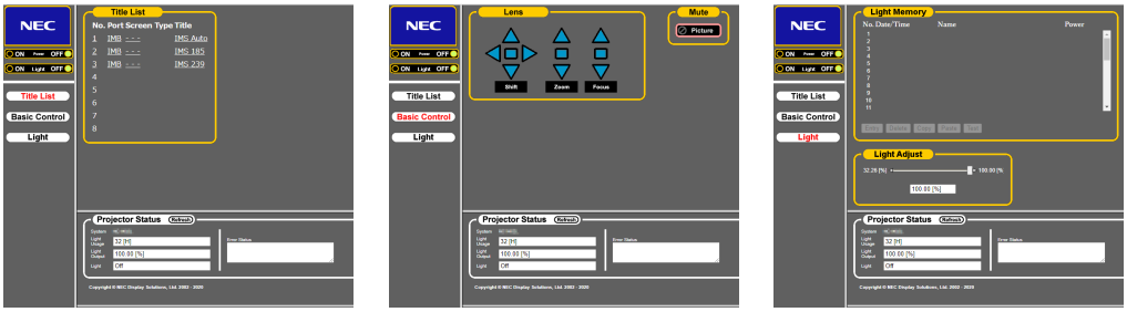
Writing of the log file (Save Information)
Log files saved on the main unit can be written to a USB memory connected to the USB port of the main unit. To perform the writing of the log file, use the following procedure.
- Connect the USB memory to the USB port of the main unit. Wait until the USB memory is recognized, and it enters the condition in which it can be used (5 or more seconds). For details, refer to the instruction guide of the USB memory.
- Simultaneously press the UP button and ENTER button.
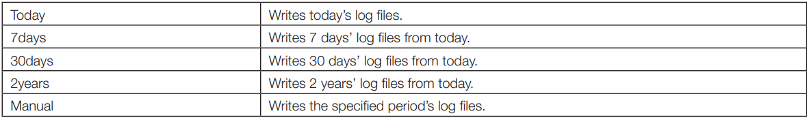
- Press the LEFT/RIGHT button, and select the log file writing period.
The items that can be selected are as follows. - Press the ENTER button.
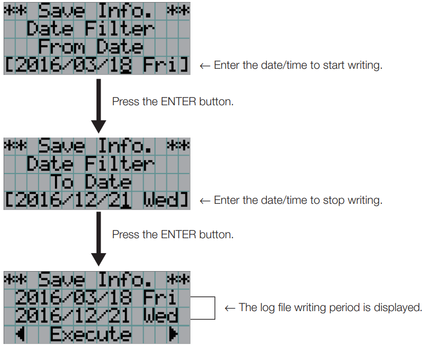
- When “Manual” is selected, specify the log file writing period. For how to enter numerals, refer to “4-1- How to enter alphanumeric characters” (See page 42). If you press the ENTER button, the display advances to the following screen.
- Confirm the log file writing period, press the LEFT/RIGHT button to select “Execute”, and press the ENTER button.
- Press the ENTER button.
- Remove the USB from the USB port of the main unit.
Names of log files
Written log files are saved with the following file names.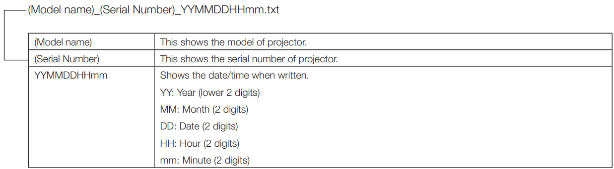
Outline Drawing
Projector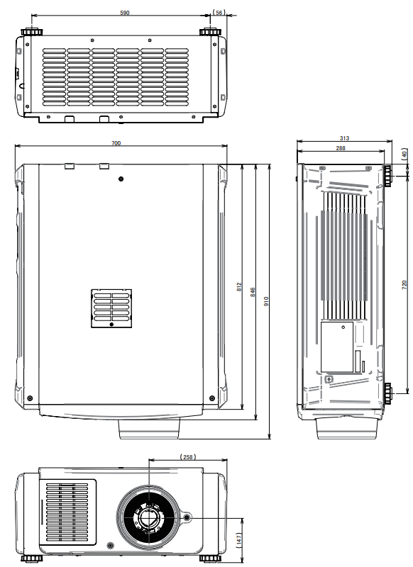
The screws specifications for Ceiling Mount: Screw type M6 S crew hole dimension on the projector: M6 with a maximum depth of 20mm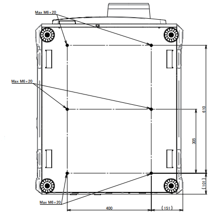
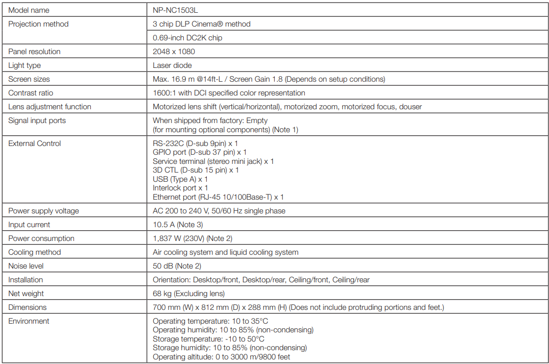
Specifications
Power Cable
Power Cable Electrical Specification
The projector is equipped with an IEC 60320 C20 Inlet to connect an AC power supply cable. Ensure that the AC power cables that connect the connectors built into the projector to the AC power maintain the current capacities as shown below.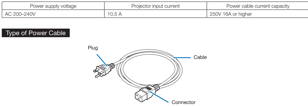
Use plugs, cables, and connectors that are suitable for the regulations of the country of installation, as shown in the following table.
USA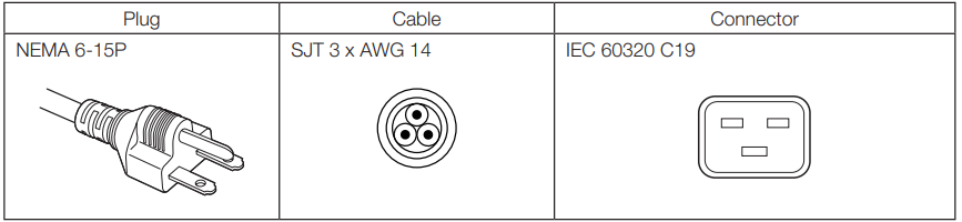
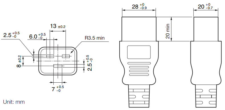
Connector
Dimensions of the connector of the power cable are shown below.
Pin Assignment and Functions of Terminal
PC CONTROL connector
This is an RS-232C interface for controlling the projector from a PC. The projector operates as a DCE (Data Communication Equipment), so use a straight cable when connecting to a PC.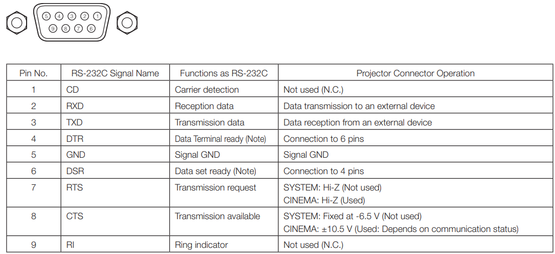
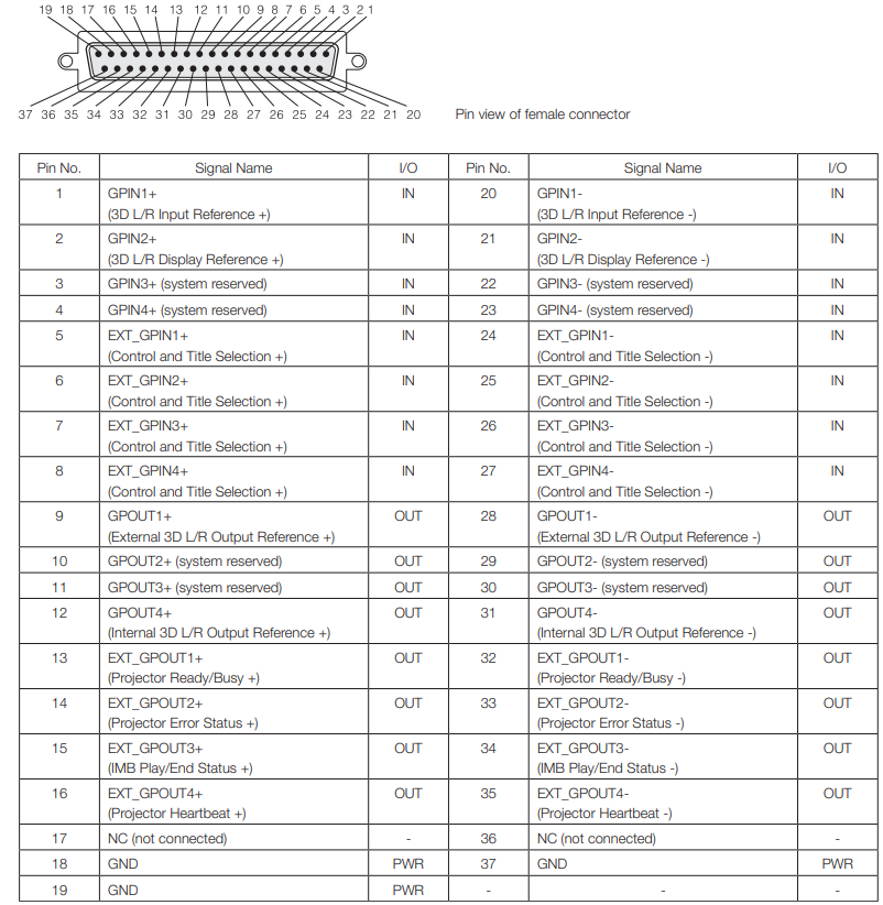
External control connector (GP I/O) (D-sub 37 pin)
It is possible to control the projector with an external device and to control the external device from theprojectorr using an external control connector (GPIO: General Purpose I/O Ports). Each pin is electrically separated from theprojector’ss externalcircuits byy a photo-coupler. 8 p8-portput and 8-port output are available. Please contact your dealer/distributor regarding how to use and to operate them.
Input Connector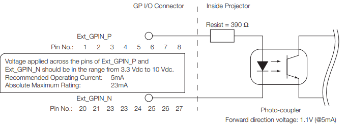
- Using GPIO Control
Momentary “ON” pulse enables you to control the projector. To enable the “ON” pulse, hold it for at least 500 ms. Hold “OFF” for at least 500 ms before “ON”. (See page 74) Here is a function list to control the projector by using the GPIO port.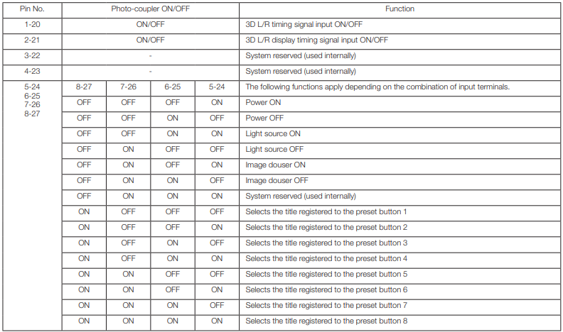
- Timing chart of GPIO control
Example of Select Preset Button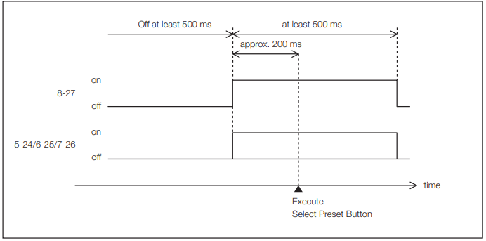
Example for turning the image douser (Douser) on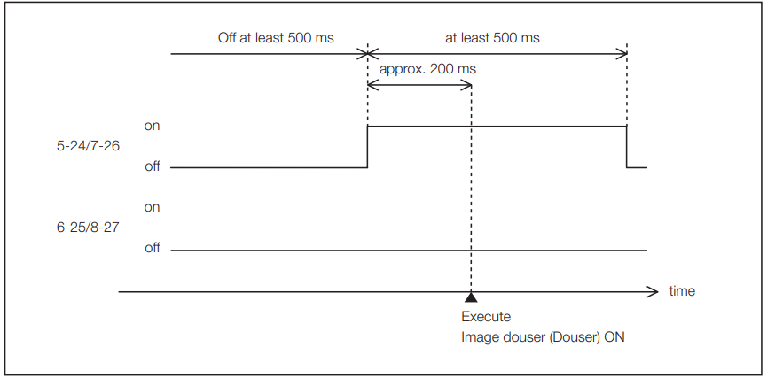 Example of Light source On
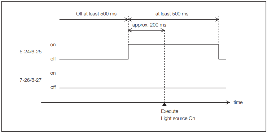
Example for turning the power off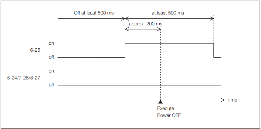
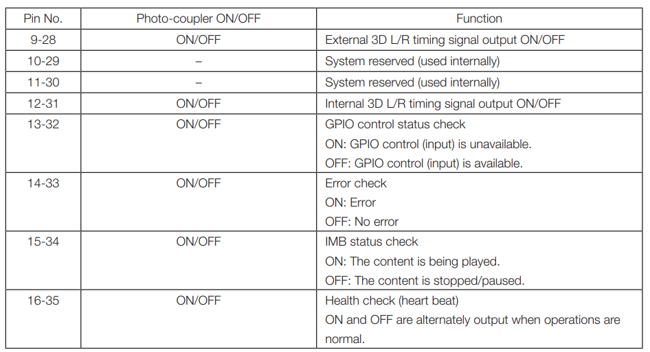
Output Connector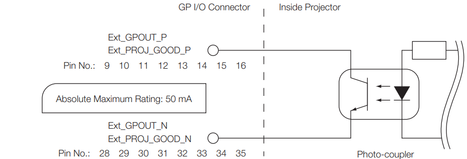
Using GPIO Control
You can use GPIO control for the projector’s health check and error check. Also, you can use the output as the trigger to control external devices. The following functions are assigned to the ppinumbers13-32, 14-33, 15-34, and 16-35 (EXT_GPOUT1 – EXT_GPOUT4) as the default. You can change the assigned functions.
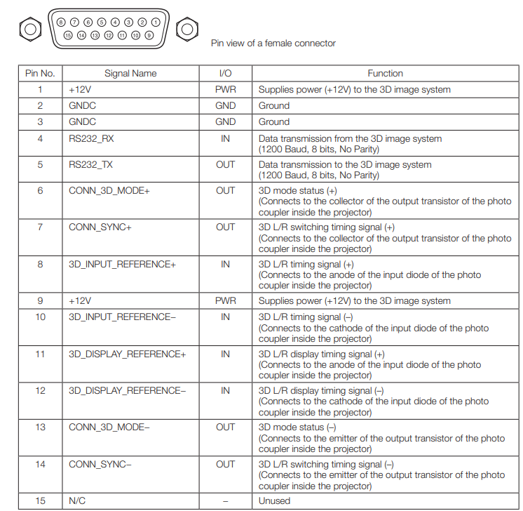
3D connector (D-sub 15 pin)
This is used to connect a 3D image system to the projector.
Related products list