
Pioneer RV050AHRMCO2L Energy Recovery Ventilator

Introduction
This user’s manual includes technical descriptions of operation, installation, and mounting guidelines, as well as technical data for the heat recovery ventilator ERV050AHRMCO2L.
Safety Instructions
- Read the user’s manual carefully before operation and installation of the heat recovery ventilator ERV050AHRMCO2L.
- Failure to follow the safety instructions may result in personal injury or ventilator damage.
- Read the manual carefully and keep it as long as you use the ventilator.
- Don’t allow children to play with the appliance.
- Don’t allow children to clean and maintain the appliance without supervision.
- Exhaust fans may adversely affect the safe operation of appliances burning gas or other fuels (including those in other rooms) by the backflow of combustible gases.
- These gases may cause carbon monoxide poisoning.
- Don’t short-circuit the power supply terminals.
- Take good care of the remote control to prevent children from attempting to swallow batteries and/or cause any related accidents.
- Do not touch the controller or the remote control with wet hands. Do not carry out ventilator maintenance with wet hands.
- Do not allow children to operate the ventilator.
- Do not clean the ventilator with water. Protect all electric parts from water ingress.
- Do not block the air duct when the ventilator is on
- Disconnect the ventilator from the power supply before maintenance.
- Do not damage the power cable while operating the ventilator.
- Do not set any objects on the power cable.
- Keep explosive and inflammable products away from the ventilator.
- Do not open the ventilator while it is operating.
- Do not direct airflow from the ventilator toward any open flames or candles.
Overview
- Ventilation Mode – The ventilator runs in exhaust or supply mode at a set speed. When synchronous operation of two connected ventilators occurs, one runs in the supply mode and the other in exhaust mode.
- Regeneration Mode – The ventilator runs in two cycles of 75 seconds each to provide heat and moisture regeneration.
- Interval 1 – The warm polluted air is extracted from the room and goes through the ceramic regenerator, which gradually absorbs heat and moisture. After 75 seconds, the ventilator switches to air supply mode.
- Interval 2 – The fresh and cold outdoor air goes through the heat regenerator and absorbs the accumulated moisture and heat after 75 seconds, and when the energy regenerator gets cold, the ventilator switches to the exhaust mode.

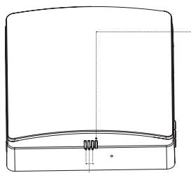
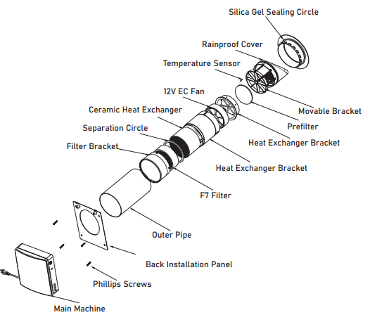
Desing & Operation
- The ventilator consists of a telescopic air duct with adjustable length regulated by the position of the inner air duct inside the outer air duct, the ventilation unit, and the ventilation hood.
- F7 filter+prefilter and the ceramic energy regenerator are located inside the inner duct. The filters are designed to purify supply air and prevent foreign objects from entering the regenerator and the fan.
- The ceramic energy regenerator extracts energy from exhaust air to warm up or cool down the supply air.
- The regenerator is equipped with a pull cord inside to facilitate its withdrawal from the ventilator. The regenerator is installed on an insulated material, which is also used as a sealant.
- The ventilator is able to be installed from the inner side of the wall.
Function Description
Status Light (RGB-LED)
- Blue light is on: Pairing mode is activated, and the linkage communication function is active between the master and slave units.
- Green light is on: IoT function is enabled, Wi-Fi is connected successfully, and the user can control the device from the phone.
- Red light is on: Filter cleaning alarm to remind the user that it is time to clean or replace the filter within the inner duct.
- Purple light is on: Indicates the master role in master-slave online mode, the master IoT networking function is enabled, and the unit can be controlled by the user’s phone.
- Green light flashes slowly: Automatic ventilation function is on and running.
- Blue light flashes slowly: Free-cooling function is on and running.
- Red light flashes three times: Indicates that the filter cleaning is complete and the cleaning time has been reset.
Function Light (RGB-LED)
- The function light indicates the fan speed. There are 3 speeds in total.
- The green light indicates air supply.
- The red light indicates air exhaust.
- The blue shows indicates regeneration mode, which switches on after 75 seconds of cyclic operation between air supply and air exhaust.

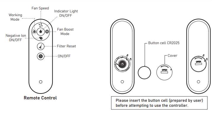
Remote Controller
- Fan Speed: Switches the fan speed of the device. There are 3 speeds in total.
- Working Mode: Switches the working mode of the device (supply mode, exhaust mode, regeneration mode).
- Negative Ion ON/OFF: Negative ion generator power socket work switch (when the negative ion function is turned on, the device supplies air with the power supply. Negative ion generator is purchased separately and added on).
- Indicator Light: Control the indicator light for On and Off.
- Fan Boost Mode: Sets the fan into fan boost mode, where the fan runs at maximum power if there is no other setting. The device runs this mode for 30 minutes before exiting automatically.
- Filter Reset: After replacing the filter of the inner air duct, press and hold the button for 5 seconds, the device’s red light flashes three times, and the filter cleaning time is reset. (Reset time default: 720 hours)
- ON/OFF: Turn ON/OFF the device.
This remote control uses an infrared signal.s
- Before using the remote control, insert the battery into the remote control and close the battery cover tightly.
- After inserting the battery, screw the battery cover clockwise as shown until the cover triangle arrow indicates the locking pattern, which means it is locked (Do not tighten the cover with your bare hands to avoid potential injury).
- To remove the battery, turn the battery cover counterclockwise as shown in the picture until the triangle arrow of the cover indicates the unlocking pattern. Once loose, the battery can be removed.
- Please store the remote control properly to prevent children from attempting to swallow batteries and/or other potential accidents.
Synchronization Function
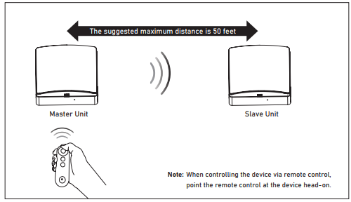
- Without setting a master/slave role, one remote control can control one or more devices.
- After setting the master/slave role, the current use of the remote control can only control the master, and the master forwards the synchronization signal to the slave (the slave does not receive the remote control signal), so that the slave mode is synchronized with the master. (The master can only control one slave alone.)
- In regeneration mode, the operation direction of the slave fan is opposite to that of the master, and the direction of the slave fan in other modes is the same as that of the master.
- The maximum linear unobstructed communication signal distance between master and slave is 50 feet.
- The signal from the master and slave can pass through an up to 7-inch thick brick wall.
Settings
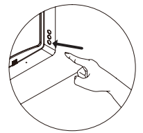
- Connect the device to power. In the OFF state, as shown in the figure, press and hold the fan speed button of the unit for 5 seconds, and the status indicator’s blue light flashes slowly.
- Once done, the device enters master-slave linkage mode and is set to the master role.
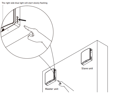
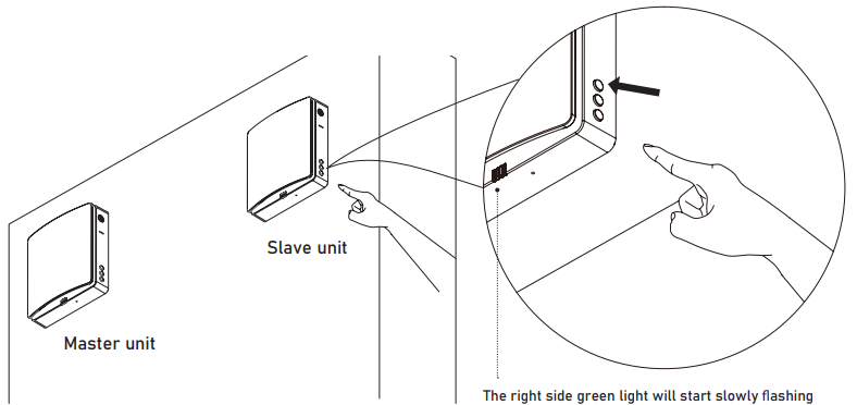
Slave Unit Settings
- Connect the device to power. In the OFF state, as shown in the figure, press and hold the mode button of the device for 5 seconds, and the status indicator green light will start flashing slowly.
- During the master and slave set pairing mode, it must be carried out at the same time within a limited time (within 1 minute). The devices should be as close as possible. The devices will be automatically connected.
- The status light of the paired devices will change to blue light ON to indicate that the master-slave pairing is successful.
- If the master-slave pairing fails, the status lights on the devices will flash for one minute before the lights turn off automatically.
Reset & Cancelation
Connect the device to power. In the OFF state, long-press the fan speed button of the linked device for 5 seconds, and the device status indicator’s blue light will start flashing slowly. At this time, the linked device enters master-slave linkage mode, and the device defaults to the master role. It should be carried out at the same time within a limited time (within 1 minute). Wait for the status indicator lights to come off automatically, whereby the device disconnects from the slave to break off the master-slave pairing automatically. At this stage, the device is reset and restored to the factory state, without any role definition.
Wi-Fi Connection
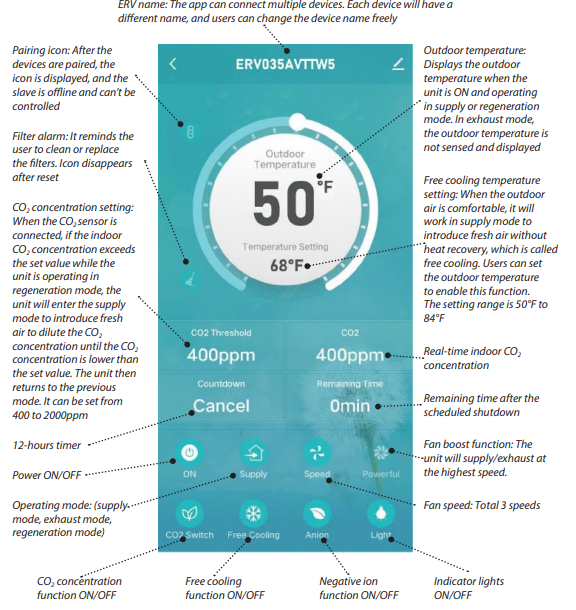
CO2 Version
Installation of the “Pioneer Airlink” smartphone application
- Search for “Pioneer Airlink” in the Google Play Store (for Android users) or the App Store (for iOS users). Note that a 2.4GHz Wi-Fi connection is needed to use the Wi-Fi control feature.

Wireless Control App Setup Process
- Registration and Log-In
- Approve the “User Agreement” and “Privacy Policy” when they appear by tapping “I Agree”.
- Tap the “Sign Up” button, choose your country, and enter your mobile number/e-mail to register, tick “I Agree” on “User Agreement and Privacy Policy”, then tap the “Get Verification Code” button. The phone or e-mail that you’re registering will receive a registration verification code.
- Enter the verification code and select a password. You will then either land on the homepage of the App, or back to the login interface to log into the app, by using the account you just created.
Adding a New Device
- Tap the “+” at the top-right corner of the homepage to enter the device selection page.
- Fast flashing indicates Wi-Fi connection, slow flashing refers to the hotspot network.
IOT NETWORKING OPERATION STEPS
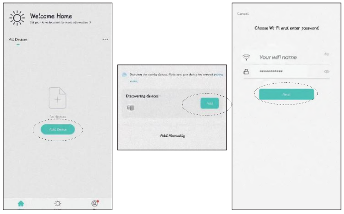
- Open the downloaded Pioneer Airlink app, enter the operation page, click the add device box, and search for devices.
- At this time, the app receives the signal from the device, then proceeds to add the device for network connection.
- Click Add Device to find the Wi-Fi signal of your home router, and make sure the Wi-Fi name on the app is the same as the name of the Wi-Fi connection to your phone, then log in with the Wi-Fi password.
WI-FI RESET AND CANCELLATION

Remove the device
- Click on the remove device option and confirm to successfully disconnect the device from Wi-Fi.
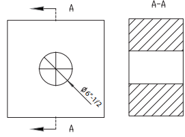
Installation Drawing
Installation
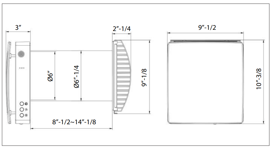
- Drill a 160~170 mm (6”-1/4~6”-3/4) round Pioneer RV050AHRMCO2L Energy Recovery Ventilator hole in the wall.

- Insert the PVC pipe into the hole. Adjust the pipe so it fits flush with both the interior and exterior sides of the wall. Use PU foam to fill the gap between the PVC pipe and the wall, both indoors and outdoors.
- Insert the PVC pipe into the wall. Adjust the pipe to fit snugly against the wall. Use PU foam to fill the gap between the PVC pipe and the wall, both inside and outside the building
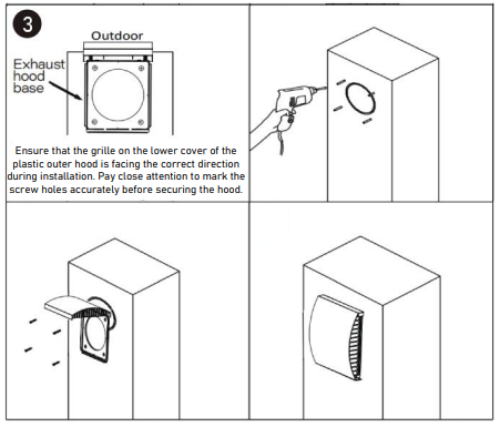
- Open the hood cover and align the bottom Pioneer RV050AHRMCO2L Energy Recovery Ventilator of the hood base with the circular opening of the pipe.
On the outside of the wall, mark the positions for the four screw holes on the base of the exhaust hood. - Drill the holes, then secure the bottom of the plastic hood using appropriate hardware.
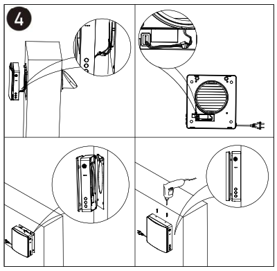
- Install the main unit on the indoor surface wall. Connect the adapter wire from the back of the main unit to the wiring of the fan and temperature sensor exposed in the inner duct, and tidy the wiring.

Use
- The telescopic design of the fans allows for installation in walls ranging from 215 mm (8”-1/2) to 360mm (14”-1/8) thick.
- The transported air must not contain any flammable or explosive mixtures, evaporation of chemicals, coarse dust, soot and oil particles, sticky substances, fibrous materials, pathogens, or any other harmful substances.
Packing List
| Ventilator | 1x |
| Accessories Bag | 1x |
| Remote Controller | 1x |
| User’s Manual | 1x |
| Packaging Box | 1x |
Ventilator Overall Dimensions (in.)
Specifications
- The ventilator is classified as a Class II electric appliance.
- The Ingress Protection (IP) rating is IPX4.
- The ventilator design is subject to continunous improvement, so some models may differ slightly from the models described in this manual.
| Description | Unit | Value |
| Voltage | V | 100-240 |
| Frequency | Hz | 50/60 |
| Input Power | W | 9.7/10.7/11.5 |
| Current | A | 0.14/0.15/0.16 |
| RPM (rated) | – | 1000/1550/1800 |
| RPM (max) | – | 2200 |
| Airflow (L/M/H) in supply/exhaust mode (with F7 filter)* | m3/h | 20/40/50 |
| Airflow (L/M/H) in regeneration mode (with F7 filter)* | m3/h | 10/20/25 |
| Airflow in supply/exhaust mode (with F7 filter)* | CFM | 11.8/23.5/29.4 |
| Airflow in regenerator mode (with F7 filter)* | CFM | 5.9/11.8/15 |
| Max airflow (under fan boost mode) | m3/h | 60 |
| Max airflow (under fan boost mode) | CFM | 35 |
| Sound Pressure Level | dB(A) | 32.7 |
| Heat Recovery Efficiency | % | up to 97 |
| Ingress Protection Rating | – | IPX4 |
| Air Duct Diameter | mm (in.) | 158 (6”-1/4) |
| SEC | – | Class A |
| Mounting Type | – | Wall Mounting |
| Net Weight | kg (lb) | 4.2 (9.25) |
Maintainance

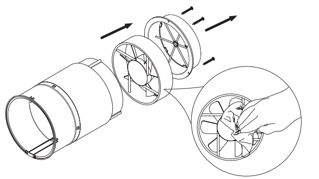
Fan Maintenance (Once Per Year)
- Remove the secured bracket from within Pioneer RV050AHRMCO2L Energy Recovery Ventilator the inner duct and take out the fan.
- Clean the impeller blades. Use a soft brush, a doth, or a vacuum cleaner to clean the impeller.
- Do not use water, abrasive detergents, solvents, or sharp objects.
Storage & Transportation
Store the ventilator inside the manufacturer’s original packing box in a cool, dry place. The storage environment must be free of any aggressive Pioneer RV050AHRMCO2L Energy Recovery Ventilator vapors and chemical mixtures that may cause corrosion, insulation, and sealing deformation.
Use lifting equipment for handling and Pioneer RV050AHRMCO2L Energy Recovery Ventilator storage operations to prevent the ventilator from damage as a consequence of failing or excessive vibration. Fulfill the handling requirements relevant to the applicable freight type.
Take care to avoid any mechanical shocks and sharp ends during handling operations.
Troubleshooting
| Fault | Possible Causes | Troubleshooting |
| The fan does not start up | No power supply | Make sure that the ventilator is properly connected to the power and make any corrections, if necessary. |
| The motor is stuck, or the impellers are clogged. | Turn the ventilator off. Troubleshoot the motor jam and the impeller blockage. Clean the blades. Restart the ventilator. | |
| Low airflow | Low fan speed setting | Set a higher speed |
| The filter, fan, or exchanger is dirty | Clean or replace the filter, and clean the fan and the exchanger. For exchanger and filter maintenance, see page 22. | |
| Noise/vibration | The impeller is dirty | Clean the impeller |
| Loose connection of the ventilator casing or the ventilation hood | Tighten the screws of the ventilator or the outer hood | |
| Master-Slave pairing failed | Master-Slave units set by a different controller | According to the manual, use the same remote controller for the Master-Slave units settings |
| The ventilator is installed where it is surrounded by a lot of metal/ there are many sources of interference | Excessive metal structures and interference sources around will weaken the wireless signal. Remove these sources of signal interference or change the installation location | |
| The distance between the Aster and Slave units is too long/the wall between them is too thick. | Please change the installation location according to the distances shown in the manual.l | |
| Other | Please reset the master-slave setting (press and hold the RESET button for ten seconds), and set it again after a period of power off. | |
Customer Support
- Address: Parker Davis HVAC International 7290 NW 77th Court, Doral, FL 33166 – USA
- Tel: (305) 513-4488
- Fax: (305) 513-4499
- E-mail: info@pdhvac.com
- Website: www.pdhvac.com
- Scan the code below to visit our support page, where you can find more installation materials:

FAQs
Q: What is the purpose of the Pioneer RV050AHRMCO2L ventilator?
Ans: This machine improves interior air quality and lowers heating or cooling expenses by ventilating fresh air while recovering energy from the stale air that is expelled.
Q: How does the energy recovery feature work?
Ans: To minimise energy loss and preserve fresh airflow, the ventilator moves heat and moisture between the incoming and departing air streams.
Q: What spaces is this ventilator suitable for?
Ans: It is made for homes or small businesses that need energy efficiency and regulated ventilation.
Q: What is the air flow capacity of the RV050AHRMCO2L?
Ans: For average room ventilation, this model can handle about 50 cubic feet per minute (CFM).
Q: How do I install the unit?
Ans: A certified HVAC specialist should perform the installation, guaranteeing correct electrical wiring, duct connections, and adherence to regional codes.
Q: Can the unit operate continuously?
Ans: In order to guarantee steady fresh air exchange and interior air quality, it is indeed made to run continuously.