
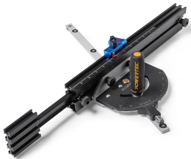
POWERTEC 71766 Miter Gauge Fence System
Safety Instructions
For your own safety, read the machine’s instruction manual before using any accessory. Failure to heed these warnings may result in serious personal injury and damage to the tool and the accessory.
- Before using the Precision Miter Gauge Fence System, read and follow all instructions and safety information provided.
- Always keep your hands clear of the blade, cutter, sanding disc/belt.
- Before making adjustments to the Precision Miter Gauge Fence System, turn off the power, allow the blade, cutter, or sanding disc/belt to come to a complete stop, and unplug the machine.
- Ensure the handle and lock knob are tight before using.
- Before turning on the power after adjustments, ALWAYS verify there is a safe clearance between the blade and fence.
Risk of accidental starting and serious personal injury. Unplug the machine before attaching the Precision Miter Gauge Fence System.
Unpacking Content
- Miter Gauge 1
- Telescoping Fence, 3″ x 1-3/8″ x 20″ with 12″ Movable Scale 1
- 3″ Fence Flip Stop with Pointer 1
- Extra Expansion Discs (Retain for future use) 4
- M4 Screws (for Expansion Discs) 4
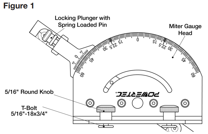
- 5/16″ Round Knobs 2
- T-Bolt 5/16″-18×3/4″ 2
- 3 mm Hex Wrench 1
- 2.5 mm Hex Wrench 1
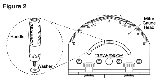
- Handle 1
- Washer for Handle 1
Assembly
Place the washer onto the handle threads and thread the handle onto the guide bar. Tighten the handle.
Setting
- Align both the Miter Gauge Head and Indexer to 0°. Lock the Adjustment Plunger.
- Use a square to verify that the miter bar and miter gauge face are perpendicular.

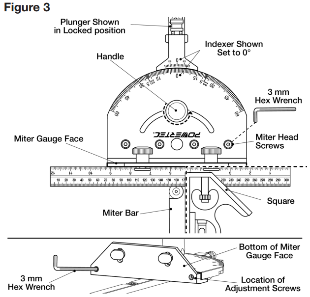
If not square or requires resetting
Use the include. Ded 3 mm hex wrench to loosen the four screws on top of the miter head. Back out the two screws on the bottom of the miter gauge face. Use a square to set the face perpendicular to the miter bar. Re-tighten the four screws on the top of the miter gauge. Run the two scews on the bottom face of the miter, in until they just touch the miter gauge head. Use a square to verify that the perpendicular face has shifted.
Fitting Miter Gauge
See Figures 4, 5. If the tool is equipped with a T-slotted miter slot, use the 3 mm hex wrench (included) to ensure the screw holding the miter bar plate is tight. If the tool is not equipped with a T-slotted miter slot, remove the plate. Save this part.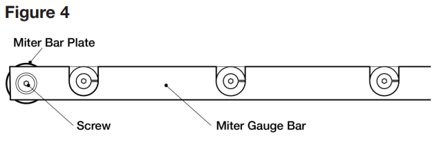
Place the miter bar into the miter slot on the saw table and check for side movement. If the miter gauge guide bar moves freely through the miter slot and has no side-to-side play, no adjustment is needed.
If an adjustment is needed
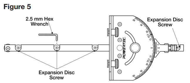
Use the four expansion discs located on the top of the miter bar to adjust any side movement. Use the 2.5 mm hex wrench (included) to tighten the screws until all side motion is removed. Turn the screws clockwise to tighten the fit and counterclockwise to loosen the fit. Ensure the bar slides freely in the miter slot.
To Square the Miter Gauge
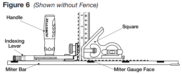
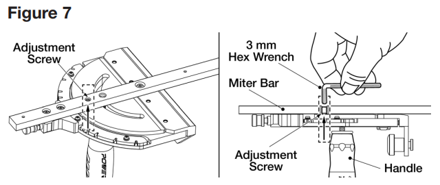
See Figures 6, 7. The miter bar features an adjustment screw that allows the miter gauge face to be set perpendicular to the table.
To Check
- Set the indexing lever to 0° and engage the spring-loaded pin.
- Tighten the handle and place the miter bar into the miter slot.
- Use a square to check the perpendicularity of the face to the table. If square, no adjustment is needed.
If an adjustment is needed
- Remove the miter bar from the miter table slot and flip it over.
- Loosen the handle.
- Locate the adjustment screw on the bottom of the miter bar, and adjust with the 3 mm hex wrench (included).
- Tighten the handle and recheck. Repeat until square.
Install the Fence
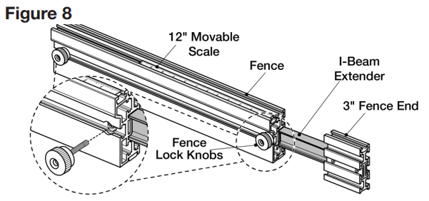
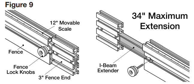
- To expand the Fence and/or switch Fence position, loosen the two Lock Knobs and pull the 3″ Fence End out to the desired length and secure Lock Knobs. The I-Beam Extender with 3″ Fence End allows an additional 17″ extension.
- The I-Beam Extender can be used on either end of the Fence. To change sides, loosen the Lock Knob, remove the 3″ Fence End with I-Beam Extender. Locate the I-beam profile on the other end of the Fence and insert the I-beam into the Fence. Tighten Knobs.
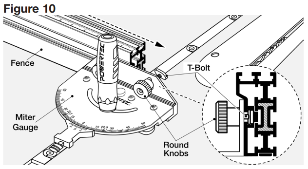
- Remove Fence Lock Knob. Loosen the two 5/16″ Round Knobs on the Miter Gauge and slide the T-bolts into the Fence slot.
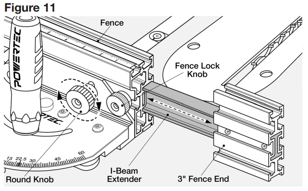
- Insert I-Beam Extender with 3″Fence End. Set to the desired length. Tighten 5/16″ Round Knobs on Miter Gauge. Reinsert Fence Lock Knobs and tighten to secure the I-Beam Extender in position.
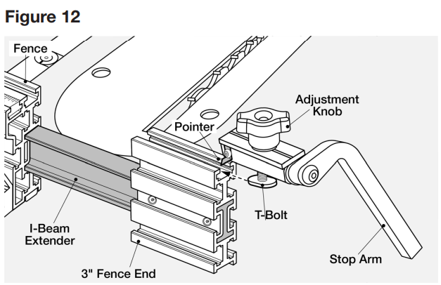
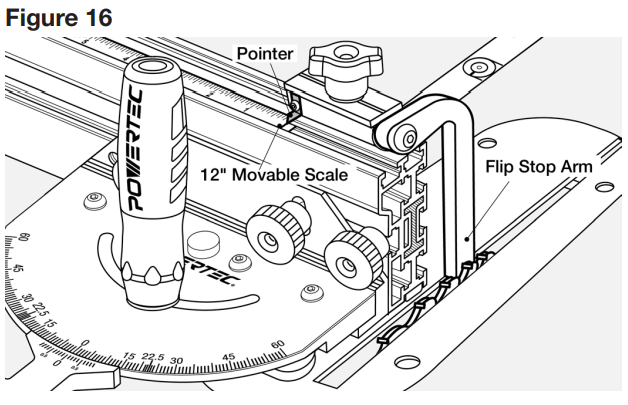
Insert the Flip Stop
- Slide the T-Bolt into the slot on the top of the Fence or 3″ Fence End (shown with 3″ Fence End). Position the arm as needed and tighten the Adjustment Knob.
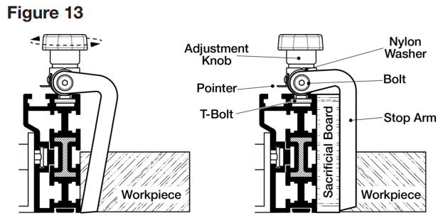
- This Fence Flip Stop is extremely versatile. The Stop Arm can be used with or without a sacrificial board. If using a sacrificial board, the angle of the specially designed arm accommodates the extra 3/4″ width and flips down. No conversion or adjustment is required.
- To reposition the flip arm, use a 5 mm hex wrench (not included) to remove the bolt and move the flip arm assembly to the required side of the body. Make sure the ure nylon washer is between the flip arm and, body and the lace bolt.
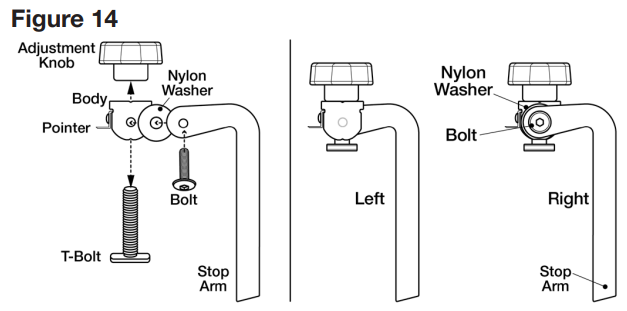
The Fence Flip Stop arm can be positioned to the Left or right of the body. Remove the Adjustment Knob athe nd T- Bolt. Rethe move Bolt, Arm, and Nylon Washethe r of Flip Stop. Reposition and assemble on the opposite side of the ody.
The Fence is equipped with a high-quality 12″ Movable Scale. Calibrate the scale by using the pointer on the flip stop to provide accurate measurements. Use the Pointer to conveniently set the workpiece length.
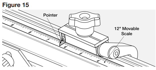
Calibrating the Scale
- Set the Fence a safe distance from the blade.
- Place the right side of the flip stop to left side set toothe th.
- Align the 0 mark of the scale to the pointer.
The Precision Miter Gauge Fence System is now ready to use.
NOTE: This Miter Gauge is designed to work with the included Fence. It can also be used as a conventional miter gauge.
How to Use
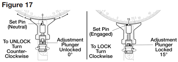
See Figure 17. Loosen the Handle. To unlock the Adjustment Plunger, pull and twist left (counter clockcounter-clockwiselunger is now in neutral position. The Miter Gauge will now move freely side-to-side.
Always keep the Adjustment Pluthe ngethe r in UNLOCKED position when mothe ving set pin to any location. Failure to do so may result in damage to the Miter Gauge.
If the desired angle is a positive stop, pull the Adjustment Plunger and twist right (clockwise). Allow set pin to drop into the notch of the detent positive stop. Release the spring-loaded spring-loaded into place. Tighten the handle. If the desired angle is not a positive stop, maneuver the Miter gauge e the desired angle and tighten the handle.
For Example
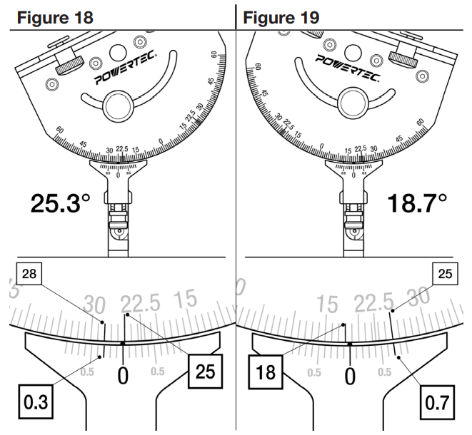
The protractor scale on the Miter Gauge head acts like a Vernier scale, and precise angles can be set.
- Loosen the handle and unlock the POWERTEC 71766 Miter Gauge Fence System adjustment plunger.
- Figure 18 shows the gauge set to 25.3 degrees. Zero is past 25 degrees, mark, and the upper and lower scales line up 3 marks past zero on the lower scale.
- In Figure 19, zero is past18-degreeegree mar18-degree. The upper and lower scales line up 7 marks past zero on the lower scale, for a measurement of 18.7 degrees.
- When the angle is set, tighten the handle.
Customer Service
- Distributed by: Electus Distribution Pty Ltd 46 Eastern Creek Dr, Eastern Creek NSW 2766 Australia
- Ph: 1300 738 555
- Website: www.electusdistribution.com.au
FAQs
Q: What is the POWERTEC 71766 Miter Gauge Fence System?
It is an adjustable fence system and precision mitre gauge intended for use with band saws, table saws, and other woodworking equipment to produce precise crosscuts and angled cuts.
Q: What materials is it compatible with?
Wood, plywood, MDF, soft metals, and other comparable materials can all be used with the technology. Make sure the saw blade you are using is suitable for the material you are cutting.
Q: Can I adjust the fence angle?
Indeed. On either side of the 90° reference, the fence system can be adjusted from 0° to 60°. For exact setting, use the locking knob and angle indication.
Q: How do I secure the workpiece?
To secure your workpiece firmly against the fence and stop it from moving while cutting, use the integrated clamp or hold-down feature.
Q: Can I make repeat cuts with the system?
Indeed. Repeatable cuts at the same length or angle can be made without measuring again, thanks to the adjustable stop block.
Q: Is the miter gauge compatible with all table saws?
The majority of common 3/4-inch or 19mm mitre slots are compatible with the 71766. Before buying, measure the mitre slot on your saw.
Q: Can it handle angled cuts other than 45°?
Indeed. The system can be changed for unique angled cuts and supports a broad range of angles, usually from 0° to 60°.
Q: Can I use the gauge for bevel cuts?
Indeed. The mitre gauge can help with sophisticated woodworking compound cuts when used in conjunction with a tilting saw blade.