


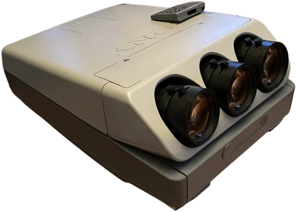
Sony HDIH-1200 HD Projection Head
THIS APPARATUS MUST BE EARTHED
IMPORTANT
The wires in this mains lead are coloured in accordance with the following code:
- Green-and-yellow: Earth
- Blue: Neutral
- Brown: Live
As the colours of the wires in the mains lead of this apparatus may not correspond with the coloured markings identifying the terminals in your plug, proceed as follows: The wire which is coloured green-and-yellow must be connected to the terminal in the plug which is marked by the letter E or by the safety earth symbol + or coloured green or green-and-yellow. The wire, which is coloured blue, must be connected to the terminal that is marked with the letter N or coloured black. The wire, which is coloured brown, must be connected to the terminal that is marked with the letter L or coloured red.
For the Customers in the USA
Warning — This equipment generates, uses, and can radiate radio frequency energy, and if not installed and used in accordance with the instructions manual, may cause interference to radio communications. It has been tested and found to comply with the limits for a Class A computing device pursuant to Subpart J of Part 15 of the FCC Rules, which are designed to provide reasonable protection against such interference when operated in a commercial environment. Operation of this equipment in a residential area is likely to cause interference, in which case the user, at his own expense, will be required to take whatever measures may be required to correct the interference.
Precautions
On safety
- Check that the operating voltage of your unit is identical to the voltage of your local power supply. i If voltage adaptation is required, consult your Sony dealer or qualified personnel.
- Usę the supplied AC power cord (mains lead). Do not use an extension cord.
- Should any liquid or solid object fall into the cabinet, unplug the unit and have it checked by qualified personnel before operating it any further. ¢Unplug the unit from the wall outlet or set the MAIN POWER switch to OFF if it is not to be used for several days. To disconnect the cord, pull it out by the plug. Never pull the cord itself.
On installation
- When the unit is mounted on the ceiling, the Sony projector suspension support PSS-1270 must be used for installation. i
- Allow adequate air circulation to prevent internal heat build-up. Do not place the unit on surfaces (rugs, blankets, etc.) or near materials (curtains, draperies) that may block the ventilation holes. Be aware that room heat rises to the ceiling; check that the temperature near the installation location is not excessive.
- Do not install the unit in a location near heat sources such as radiators or air ducts, or in a place subject to direct sunlight, excessive dust or humidity, mechanical vibration, or shock.
- To avoid moisture condensation, do not install the unit in a location where the temperature may rise rapidly.
- Do not install the screen in a location where wind from an air conditioner may blow upon it directly.
- Use a cover over fluorescent lamps
to avoid lowering the contrast ratio. Cover any windows that face the screen with opaque fabric - lt. It is desirable to install the projector in a room where the floor and walls are not of light-reflecting material.
- To keep the cabinet looking brand-new, periodically clean it with a soft cloth. Stubborn stains may be removed with a cloth lightly dampened with a mild detergent solution. Never use strong solvents, such as thinner or benzine, or abrasive cleansers, since these will damage the cabinet.
- Avoid touching the lens. To remove dust on the lens, use a blower brush or a soft cleaning brush. To remove fingerprints or smudges, clean with a soft cloth lightly moistened with a mild detergent solution.
- Save the original shipping carton and packing material; they will come in handy if you ever have to ship your unit. For maximum protection, repack your unit as it was originally packed at the factory.
Features
The Sony High Definition projector conforms with the HDTV standards BTA S-001 and SMPTE 240M.
Bright Image Light Output 300 Lumen
The 9-inch CRT with impre-cathode, high-performance HACC lens, and newly-developed circuitry provides a bright image.
Stable Black Reproduction by LC System
LC (Liquid Coupling and Cooling) system contributes to improved high contrast and allows stable reproduction of blanks.
Fine detailed Picture Reproduction
The 9-inch magnetic focus CRT minimizes the spot size of an electron beam and reproduces a fine-detailed picture.
High Precision Registration
Analogue registration, corrected waveform, and digital control enable high precision registration with convergence error of less than 0.1%.
Other Features
- illuminated Remote Commander and control panel.
- Easy adjustment of the lens focus can be easily adjusted with the Remote Commander.
Location and Function of Controls
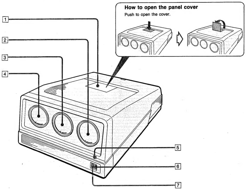
Front
Location and Function of Controls
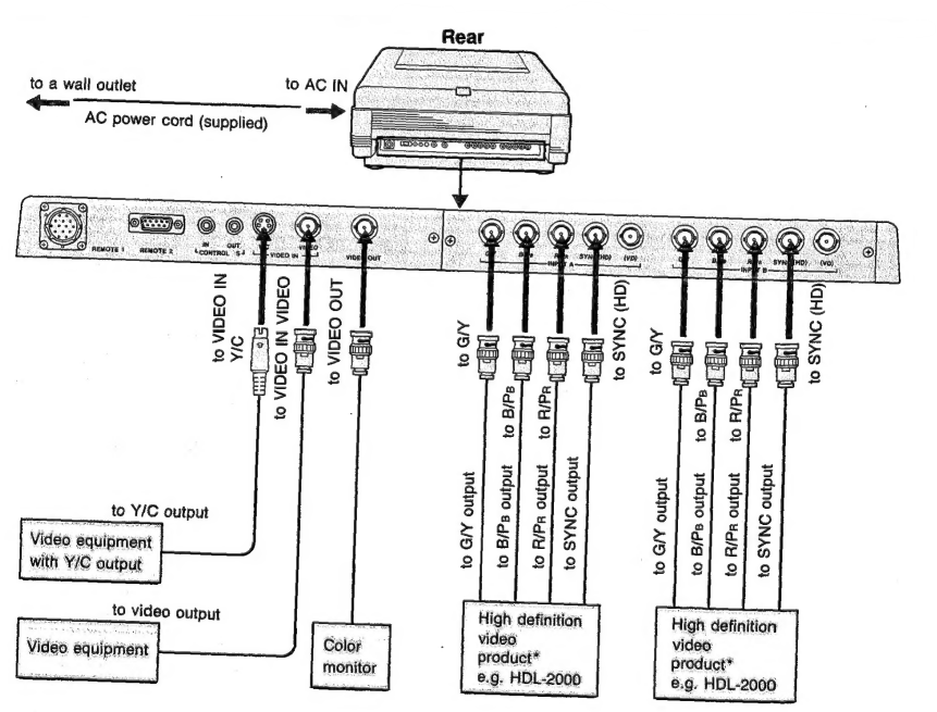
Rear
To open the connector panel cover, see “How to open the connector panel cover” on page 9.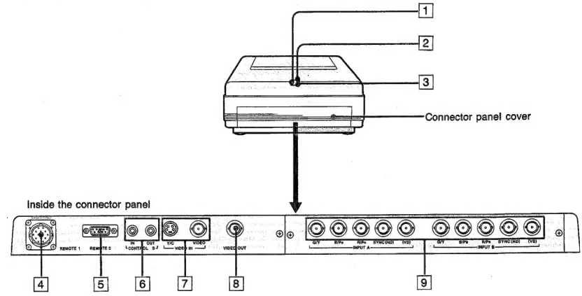
- Rear remote control detector
- STANDBY indicator: When the MAIN POWER is on, the red light indicating standby will be on.
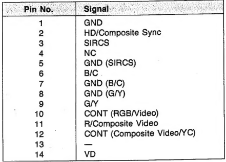
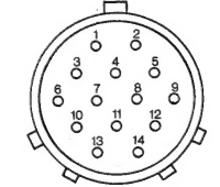
- REMOTE 1 connector (14-pin) For future use.
- REMOTE 2 connector (9-pin) For future use.
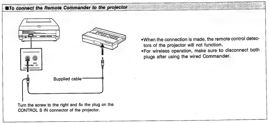
- CONTROL S IN/OUT connectors: Connect to the CONTROL S connectors of other Sony equipment. It is then possible to control! The whole system with a single Remote Commander.
- VIDEO IN connectors Y/C (4-pin): Connect to the Y/C output of a VCR. VIDEO (BNC type): Connect to the video output of video equipment.
- VIDEO OUT connector (BNC type) Loop-through output of the VIDEO connector. Connect to the video input of a VCR or another monitor. Note: The signal input from the Y/C connector is not output from this connector.
- INPUT A/B connectors (BNC type) G/Y, B/PB, R/PR. SYNC (HD), (VD): Connect to the G/Y, B/PB, R/PR, SYNC (HD), (VD) outputs of high definition video products (BTA S-001 or SMPTE 240M standard) such as HDL-2000 videodise player.
- Push to open the cover

- Slide the cover upward as far as it can go.

- Bend the cover until it is detached.

Location and Function of Controls
The same keys are on the control panel of the projector. 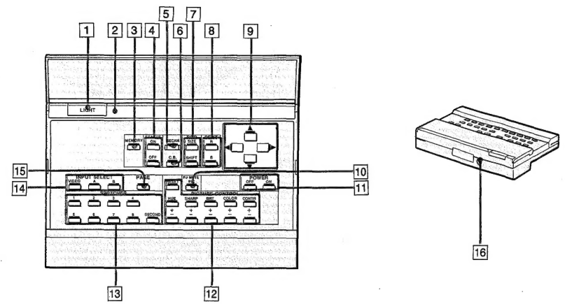
- LIGHT button Press to illuminate the indicators on the Commander. The light will go off in about 10 seconds after any operation.
- MEMORY key: Press to store the adjusted data.
- STATUS ON/OFF k, ey Prthe ess OFF key to cut the on-screen display. Press the ON key to restore the on-screen display.
- SECAM key: Press when the color of a picture from the SECAM color source is incorrect. Press again to switch over to the other standard system sources, NTSC or PAL.
- C.B. (Clear Blue) key: Press to make the blue color clear in the picture input from the INPUT A/B connectors. Press again to restore the normal condition.
- Location and Function of Controls
Location and Function of Controls
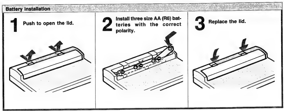
- If the projector does not operate properly, the batteries might be
- Be sure that there are no obstructions between the Commander worn out. Replace all three of them with new batteries. and the unit.
- The life of the batteries depends on the frequency of usage, how often.
- Operable range is limited. You use the LIGHT button. If they wear out quickly, replace them.
Commander
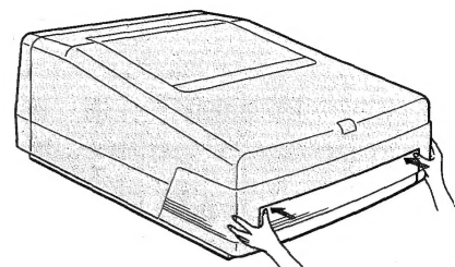
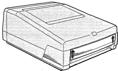
For carrying the projector, attach the supplied handles to the front and rear of the projector.
Insert the joints with the curved portion toward you into the square holes of the projector as far as they can go.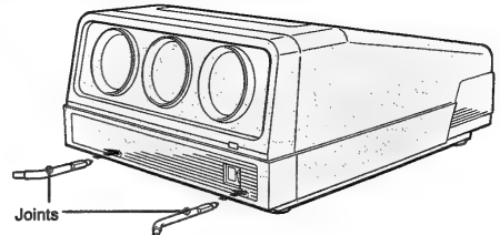
After inserting the joints, turn them upward by 90 degrees. Then, try to pull the joints to confirm that they are fixed and cannot be pulled out.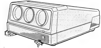
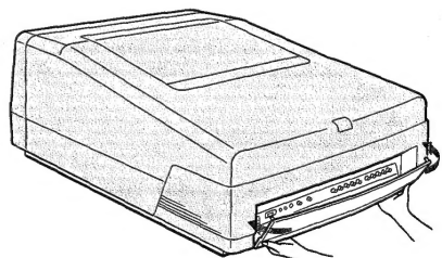
Attach the handle to the joints.
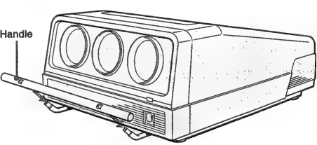
The handle may jolt slightly, even though the eye4 Fasten with the eyebolts. bolts are fastened tightly.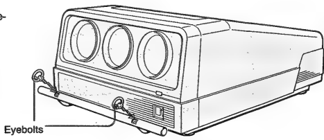
Repeat the above steps for attaching the handle at the rear of the projector.
Projecting
The keys on the control! The panel of the projector is the same as that found on the Remote Commander. 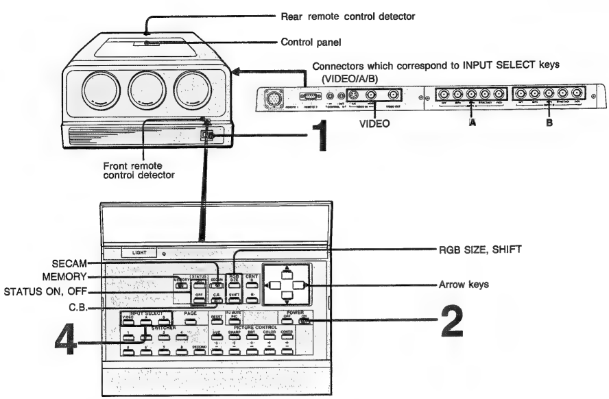
- Turn the MAIN POWER of the projector on ( | ).
- Turn the power on by pressing the POWER ON key of the Remote Commander or the control panel of the projector.
- Select the input signal to be projected by pressing the INPUT SELECT key (VIDEO, A, or B). 3 Turn on the connected equipment.VIDEO: to select the signal input from the VIDEO IN connectors
- to select the signal input from the INPUT A connectors
- to select the signal input from the INPUT B connectors
- Adjust the picture.
To cut the on-screen display
Press STATUS OFF. To restore the on-screen display, press STATUS ON.
To darken the screen (PIC MUTE)
Press the PJ MUTE PIC key. To restore the previous brightness level, press PJ MUTE PIC key again or CONTR+ key.
If the color of the picture is incorrect
When the input signal is from the INPUT A/B connectors, display PAGE 4 by pressing the PAGE key, then check that the INPUT SIGNAL setting (GBR/YPePr) is correct. When the input color source is SECAM, press the SECAM key (SECAM ON). Press again to switch over to other standard system sources, NTSC or PAL (SECAM OFF). If you wish to store the SECAM ON/OFF or C.B. ON/OFF setting, store the data (see page 23).
Projecting
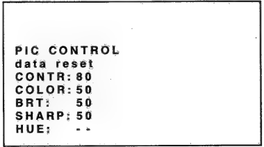
Adjusting the Picture
Use the PICTURE CONTROL keys on the Remote Commander. The adjustment levels are digitally displayed on the screen, having a range of MIN, 1, 2, …, 98, 99, MAX.
- CONTR +/- keys: +: to increase picture contrast: to decrease picture contrast
- COLOR +/- keys: +: to make color intensity vivid: to make color intensity pale
- BRT +/- keys:: to make the picture brighter: to make the picture darker
- SHARP +/- keys: +: to make the picture sharper: to make the picture softer
- HUE +/- keys:: to make skin tones greenish: to make skin tones purplish
- COLOR and HUE controls do not function on the input signal from the INPUT A/B connectors.
- HUE control does not function with a PAL or SECAM color source.
Minput signal from INPUT A/B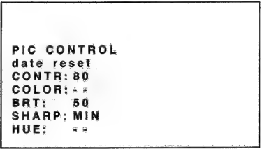
- NTC (VIDESO) input signal

- PAL/SECAM (VIDEO) input signal

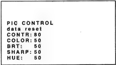
Displaying the Current Control Settings and Conditions
Press the PAGE key to display the following four on-screen displays. The displays in these illustrations are for INPUT A/B. When in VIDEO mode, the adjustable items are slightly different from the displays in these illustrations.
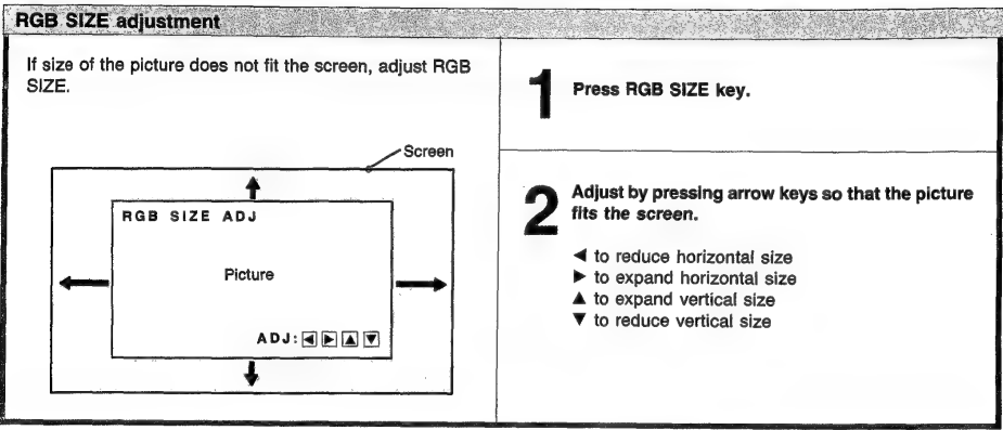
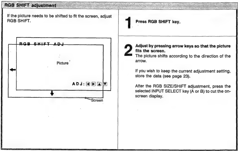
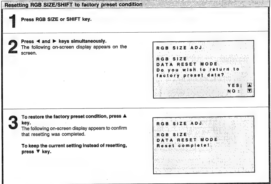
RGB SIZE and SHIFT Adjustments (For INPUT A/B only)
If necessary, adjust the size and shift of the picture using the RGB SIZE/SHIFT and arrow keys. This adjustment functions only with the input signal from the INPUT A or B connectors.
Messages on the Screen
The meaning of the color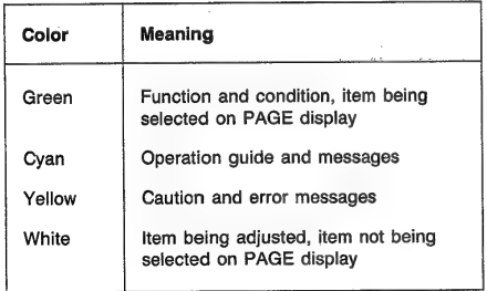
Error message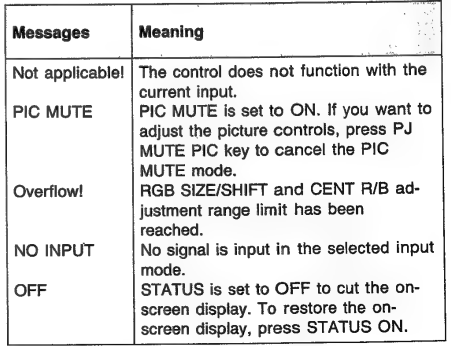
Storing the Adjustment Data
If you wish to save the picture adjustment changes, you must store them in memory. The following conditions can be stored: SECAM ON/OFF setting, CLEAR BLUE (C.B.) ON/OFF setting, The adjustment data of RGB SIZE, The adjustment data of RGB SHIFT, The setting data of PAGE 3; MEMORY numbers, The setting data of PAGE 4
- COLOR TEMPERATURE (HDTV 1/HDTV 2/
- VID +/VID 2)
- INPUT SIGNAL (GBR/YPsPr)
- COLOR SELECT (COL/B&W)
- SYNC SOURCE (INT/EXT)
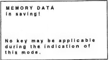
- After the adjustment, press the MEMORY key. The following on-screen display appears to indicate that storing has begun. While the display is on, no other keys will function.

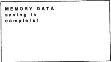
- The following on-screen display appears to indicate that storage has been completed.

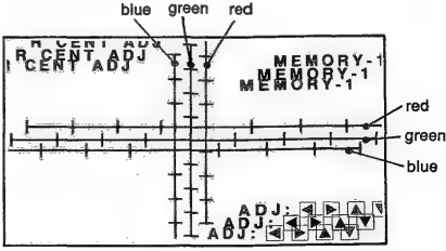
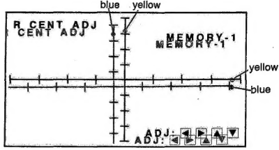
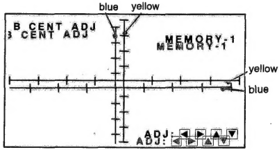
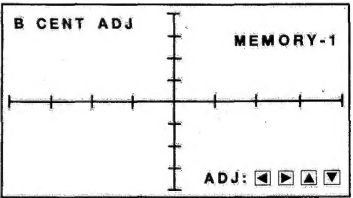
Centering Adjustment
The three colors red, green, and blue must converge for proper projection. If they do not converge, centering adjustment is necessary.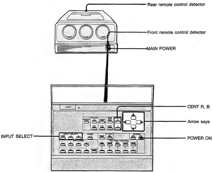
- Turn the MAIN POWER switch of the projector on ( | ) and press the POWER ON key of the Remote Commander.

- Press the arrow keys to move the red line so that the red and green lines converge. The red line will move according to the direction of the arrow.

- The built-in cross-hair test pattern will be displayed, and the blue line will be operable.

- green and red lines converge.

- Press the selected INPUT SELECT key (VI D, EO, A or B) to exit the test pattern mode.
System Connection
Notes on connection
- First, make sure that the power to each piece of equipment-
- Use connecting. A loose connection may cause hum and noise.
Specifications
Optical
Projection system
3 picture tubes, 3 lenses, Horizontal in-line system
Picture tube
9-inch liquid-cooled high-brightness tube LC? (Liquid Coupling and Cooling) system
Projection lens
High performance HACC lens F 1.24/172mm (HDIH-1200/1200M) F 1.25/174mm (HDIH-2000/2000M) F 1.25/177mm (HDIH-2400/2400M)
Projected picture size
HDIH-1200/1200M 100—130 inches measured diagonal… Factory-adjusted to 120 inches measured diagonally. HDIH-2000/2000M 150—200 inches measured diagonally. Factory-adjusted to 200 inches measured diagonally. HDIH-2400/2400M 240 inches measured diagonally
General
Light output
300 Im (white peak) „ 100 Im (all white)
Resolution (HDTV) | (VIDEO)
100 Im (all white) 1000 TV lines (at screen center) 700 TV lines (at screen center)
Horizontal frequency Vertical frequency ` Color system
15kHz—35kHz 50Hz—120Hz PAL, SECAM, NTSC, NTSCz. SCz.43 system, switched automatically
Test signal
A test pattern generator is incorporated.
Inputs
INPUT A/B: BNC connectors, 75 ohms terminated G/Y, B/PB, R/PRG: Composite, 1.0Vp-p + 2dB or non-composite, 0.7Vp-p +2dB, positive Sync signal is +0.3Vp-p trilevel bipolar sync or 0.3Vp-p sync negative. B, R: Non-composite, 0.7Vp-p +2dB, positive Y: Composite, 1.0Vp-p +2dB or non-composite, 0.7Vp-p +2dB. Sync signal is +0.3Vp-p trilevel bipolar sync. PB, PR: +0.35Vp-p, sync signal is + 0.3Vp-p tri-level bipolar sync. SYNC(HD): Composite sync or horizontal sync is +0.3Vp-p tri-level bipolar sync or 0.2-4Vp-p sync, positive/negative (VD): Vertical sync is 0.2-4Vp-p sync, positive/negative VIDEO IN Y/C: 4-pin mini DIN connector Y(luminance) signal: 1 Vp-p + 2 dB, sync negative, 75 ohms terminatedC (chrominance) signal: burst 0.286 Vp-p +2 dB, 75 ohms terminated (NTSC) 0,3 Vp-p +2 dB, 75 ohms terminated (PAL) VIDEO: BNC connector Composite video input, 1 Vp-p, +2 dB, sync negative,75 ohms terminated REMOTE 1 connector: 14-pin connector REMOTE 2 connector: 9-pin connector CONTROL S IN: minijack 5Vp-p
Outputs
VIDEO OUT: BNC connector Composite video output, 1Vp-p +2 dB, impedance 75 ohms, Outputs video signal from the VIDEO IN connector CONTROL S OUT: minij5Vp-p Vp-p
Power requirements
HDIH-1200/2000/2400: 120 V AC, 50/60 Hz HDIH-1200M/2000M/2400M: 220—240 V AC, 50/60 Hz
Power consumption
120V: 7.2A 220—240V: 4A
Dimensions
Approx. 743 x 402 x 998mm (wih/d) . (29 3/8 x 15 7/8 x 39 3/8 inches)
Weight Accessories supplied
Remote Commander RM-1200 (1) with 3 size AA(R6) batteries, Remote Commander cable (1, AC power cord (1), Handle kit (1 set)
Signal assignment
REMOTE 2 connector (D-sub, 9-pin)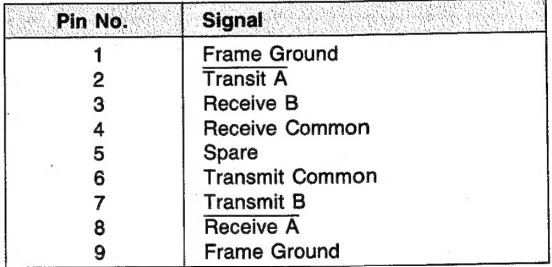
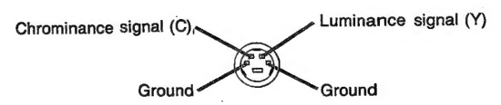
Y/C connector (4-pin mini DIN)
Customer Service
- Website: https://www.sony.com/
- Ph: 800-326-9551