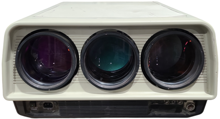
Sony VPH-2020QJ Color Video Projector
INSTALLATION DIAGRAMS
The following installation diagrams, types 1 and 2, indicate the relative positions of the projector, screen, and ceiling/floor.
TYPE 1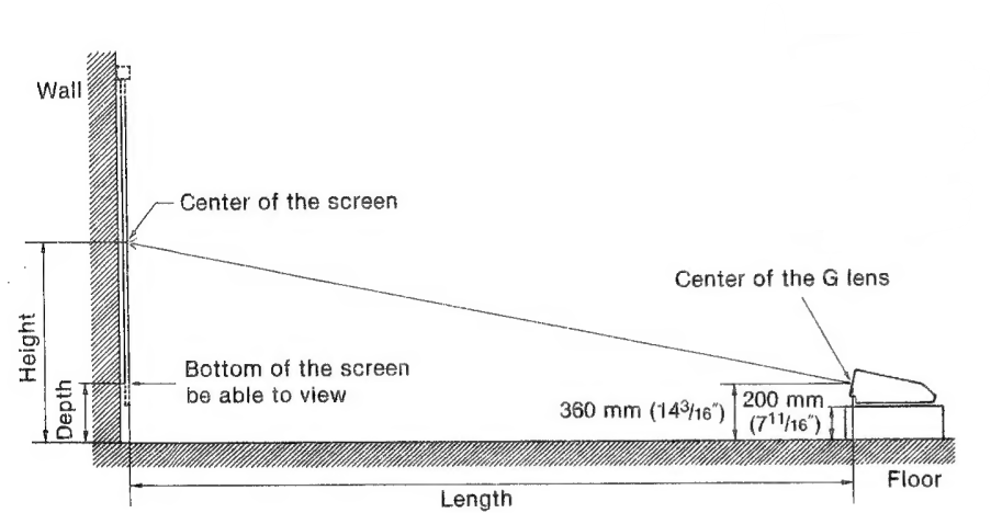
TYPE 2 installation on the ceiling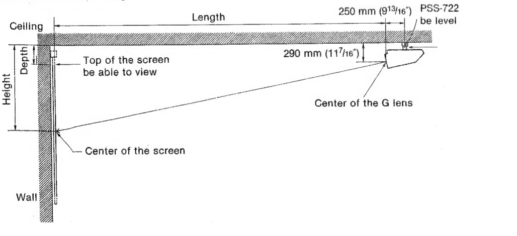
SYSTEM INSTALLATION PROCEDURE
Type 1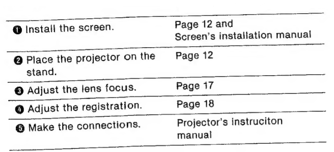
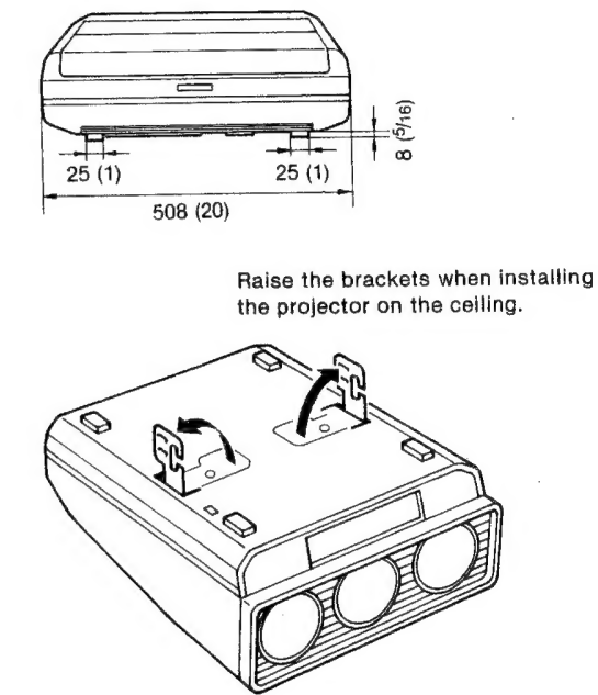
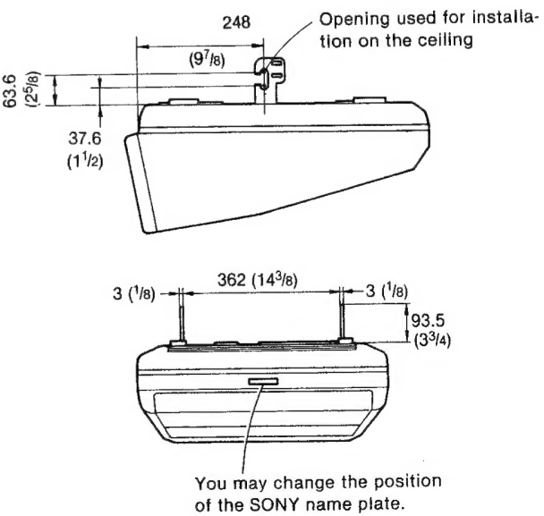
Projector’s dimensions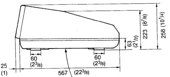
Type 2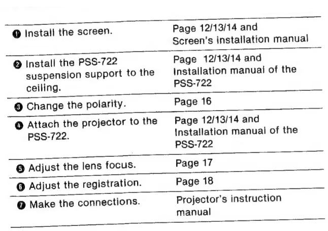
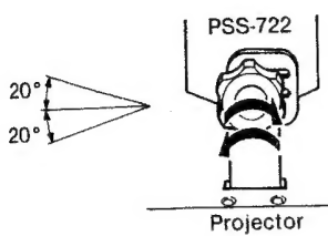
How to adjust the angle of the screen/projector: Loosen the knobs, adjust the angle, then tighten the knobs down firmly.
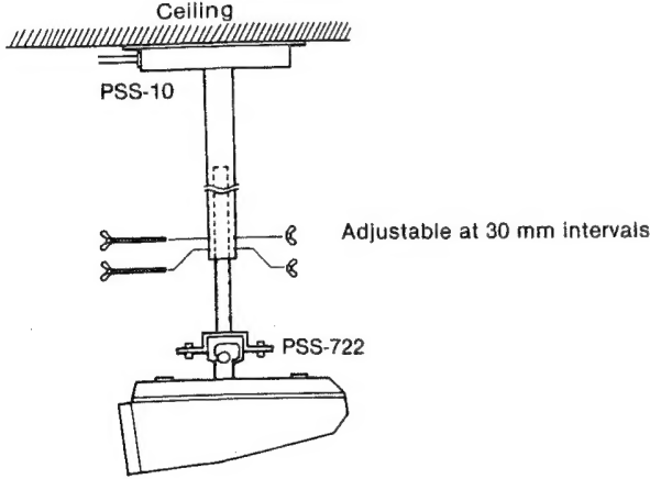
When the PSS-10 projector suspension support (optional) is used in combination with the PSS-722 The PSS-10 allows you to adjust the distance between the ceiling and the projector. @ Loosen the two screws to remove the cover.
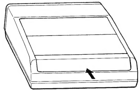
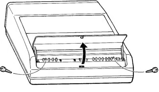
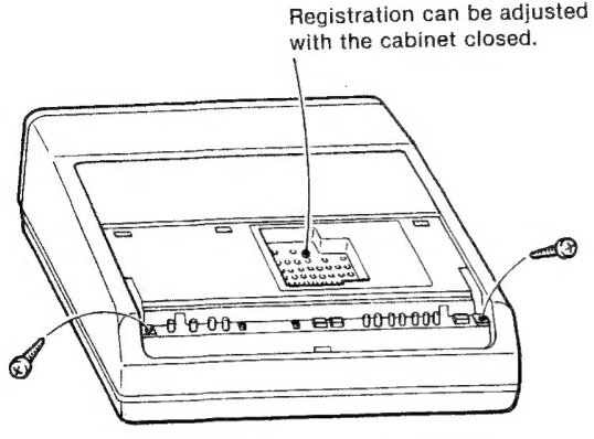
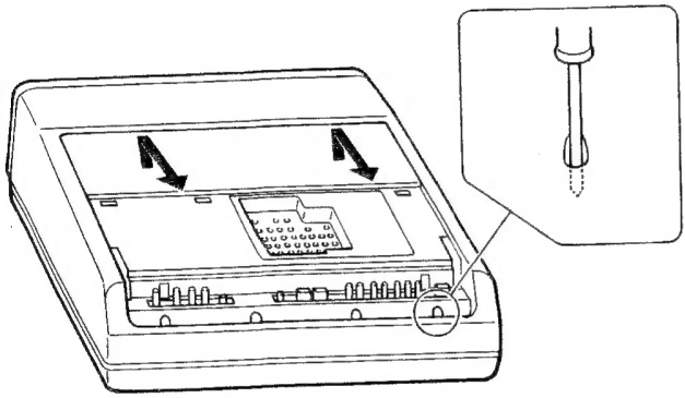
How to open the cabinet
You will need a medium-sized Philips head screwdriver.
- Push to open the cover.
- Loosen the two screws to remove the cover.
- Loosen the two screws to remove the panel.
- Loosen the four screws through the holes.
- Remove the cabinet by pulling upward and forward.
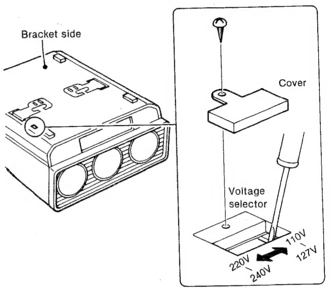
How to adjust the operating voltage
- The operating voltage preset at the factory is as follows:
- VPH-2020Q1: 120V (110- 127V) ac
- VPH-2020QM: 220-240V ac
- If adaptation to your local power line voltage is necessary, remove the cover and set the voltage selector to the appropriate position.
- After the adjustment is complete, close the cover.
Itumination
To obtain a clear picture, the screen should not be exposed to illumination or sunlight directly from the front.
Ceiling-mounted spot lighting is recommended. Use a construction as illustrated over light, see scattering illumination such as fluorescent lamps.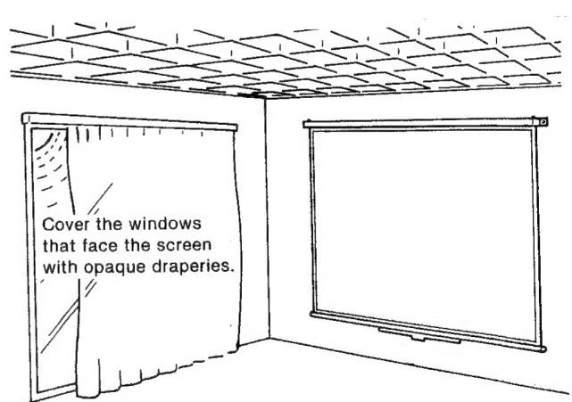
It is desirable to install the projector in a room whose floor and walls are not of light-reflecting material. If the floor and walls are of reflecting material, it would be desirable to change to a dark carpet and wallpaper.
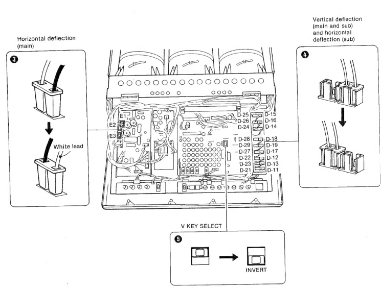
POLARITY CHANGE
The projector is pre-adjusted at the factory to be used on the stand with the bracket side down. When the projector is installed on the ceiling with the bracket side up, the polarity should be changed.
- Make sure that the power is not connected.
- Open the cabinet. (See page 14).
- Reverse the polarity of connectors E1, £2, and E3.
- Move the connectors from the right D-11 through D-19 receptacles to the left D-21 through D-29 receptacles.
- Set the V KEY SELECT switch to INVERT.
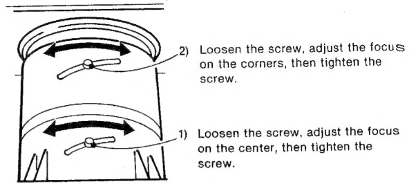
LENS FOCUS ADJUSTMENT
- Open the cabinet. (See page 14).
- Install the projector in the proper position.
- Connect the power cord supplied to the AC IN socket and to an ac outlet, turn on the POWER switch on the connector panel, then turn the PROJECTOR switch on. The green lamp will light up.
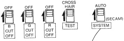
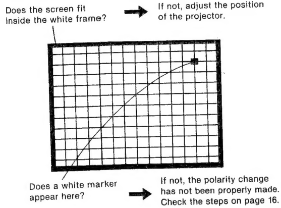
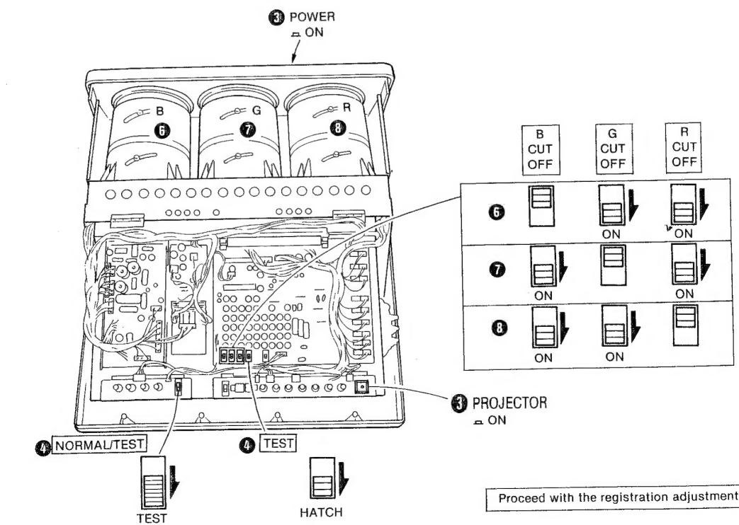
- Set the NORMAL/TEST switch to TEST and the TEST switch to HATCH. A cross-hatch pattern will be displayed.
- Check the following.
- Set the G (green) and R (red) CUT-OFF switches to ON, then adjust the focus of the blue lens.
- Set only the G CUT-OFF switch to OFF and the other switches to GN, then adjust the focus of the green lens.
- Set only the R CUT-OFF switch to OFF and the other switches to ON, then adjust the focus of the red lens.
- Close the cabinet. (Reverse the steps indicated on page 14.)
REGISTRATION ADJUSTMENT
Location of controls
Use a small, flat-headed screwdriver to adjust the controls and switches through the holes.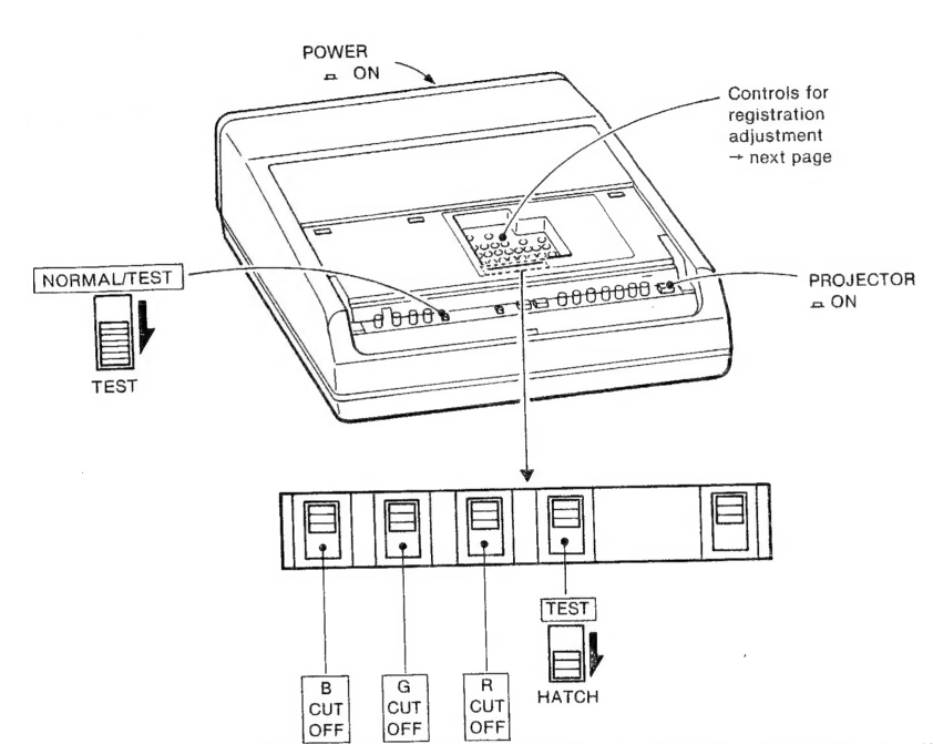
Vertical registration of the red and green pictures
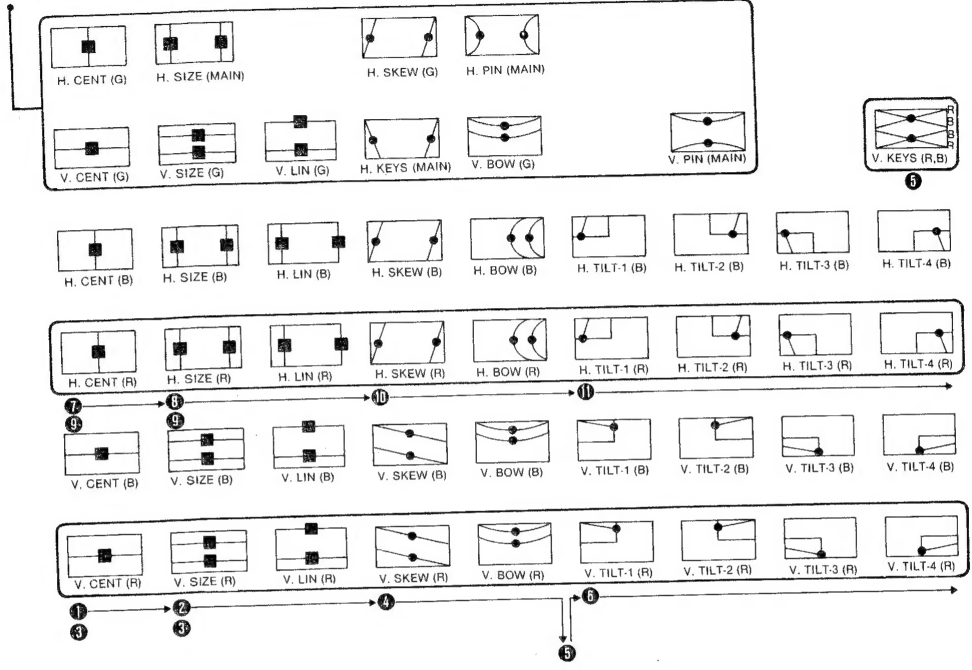
- Adjust the V. CENT (R) control so that the red horizontal lines and the green horizontal lines converge in the middle of the screen.
- Adjust the V. SIZE (R) and V. LIN (R) controls so that the red horizontal lines and the green horizontal lines converge at the upper and lower sides of the screen. Repeat steps @ and @ as necessary. Adjust the V. SKEW (R) and V. BOW (R) controls so that the red horizontal lines and the green horizontal lines converge in the middle of the screen.
- Adjust the V. KEYS (R, B) control so that the red horizontal lines at the top and bottom of the screen are parallel.
- Adjust the V. TILT-1 {R) to -4 (R) controls so that the red horizontal lines and the green horizontal lines converge in the corners of the screen.
Horizontal registration of the red and green pictures
- Adjust the H. CENT (R) control so that the red vertical lines and the green vertical lines converge in the middle of the screen.
- Adjust the H. SIZE (R) and H. LIN (R) controls so that the red vertical lines and the green vertical lines converge at the right and left sides of the screen.
- Repeat steps @ and @ as necessary.
- Adjust the H. SKEW (R) and H. BOW (R) controls so that the red vertical lines and the green vertical lines converge in the middle of the screen.
- Adjust the H. TILT-1 (R) to -4 (R) controls so that the red vertical lines and the green vertical lines converge at the corners of the screen.
Proceed with the following adjustments in the same manner as with red and green registration, except for the setting of the CUT-OFF switches.
Vertical registration of the blue and green pictures
- V. CENT (B) control
- V. SIZE (B) and V. LIN (B) controls
- Repeat steps and ®.
- V. SKEW (B) and V. BOW (B) controls
- V. KEYS (R, B) control, if required
- V. TILT-1 (B) to -4 (B) controls
Horizontal registration of the blue and green pictures
- H. CENT (B) control
- H. SIZE (B) and H. LIN (B) controls
- Repeat steps ® and ®.
- H. SKEW (B) and H. BOW (B) controls
- H. TILT-1 (B) to -4 (B) controls
When registration is complete
A Sot switches to the following positions.