


Labnet I-5311-D 311D Digital Incubators User Manual
Introduction
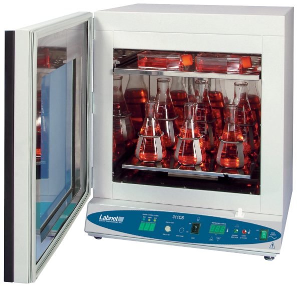
The Labnet Digital Incubators have been designed for general purpose incubations (<65°C), as well as those applications requiring higher temperatures (up to 65°C). An independent, user-settable safety thermostat protects samples and the incubator from overheating in the unlikely event of a primary controller failure.
A fan, located in the chamber, assists in providing an exceptionally uniform environment. The door of the incubator consists of two parts. The inner door is glass to allow for viewing the chamber contents without disrupting the temperature environment. The outer door is solid and insulated. It is also heated to help in maintaining the chamber temperature. The heated door prevents condensation from forming on the inner glass viewing door.
Safety Information
These units are not intended for hazardous or household locations or use. Your satisfaction and safety require a complete understanding of this unit. Read this instruction manual thoroughly before attempting to operate the incubator. All operators should be given adequate training before using this incubator.
- The electrical warning symbol indicates the presence of a potential hazard that could result in electrical shock.
- This symbol indicates a potential risk and alerts you to proceed with caution.
Unpacking
Inspection
Upon receipt of your Labnet 311D or 611D Digital Incubator, examine the carton and unit for damage. The carrier is responsible for correcting shipping damages. Carefully remove the unit from the carton and shipping pallet.
The package should include:
- Labnet 311D or 611D Digital Incubator
- 2 large shelves
- 8 shelf clips
- 4 leveling feet
- Power cord (both EU and UK cords in 230V models)
- Instruction manual
Installation
Local city, county, or other ordinances may govern the use of this equipment. If you have any questions about local requirements, please contact the appropriate local agency.
Power Source
Check the data plate for voltage, cycle, phase, and ampere requirements. If matched to your power source, plug the power cord into a grounded outlet.
Location
In selecting a location, consider all conditions that might affect performance, such as heat from radiators, ovens, autoclaves, etc. Avoid direct sun, fast-moving air currents, heating/cooling ducts, and high-traffic areas. Allow a minimum of 5 cm between the unit and walls or partitions that might obstruct free airflow.
Lifting/Handling
These units are heavy, and care should be taken to use appropriate lifting devices that are sufficiently rated for these loads. Units should only be lifted from their bottom surfaces. Doors, handles, and knobs are not adequate for lifting or stabilization.
Leveling
The unit must sit level and solidly. Adjust the foot at each corner until the unit stands level and solid without rocking. If the unit must be moved, turn the leveling feet all the way clockwise to prevent damage while moving.
Cleaning
The unit chamber should be cleaned and disinfected before use. Remove all of the interior parts, and clean thoroughly with a disinfectant that is appropriate to your application.
Controls
- Power switch: The main power ON/OFF switch controls all power to the unit. The power must be on before any systems are operational. The green switch will be lit when ON.
- Main temperature control: This control consists of the digital display and Up/Down buttons for inputting set point temperatures and calibration.
- Safety thermostat: The Safety thermostat is completely independent of the Main Controller. The Safety guards against any failure of the Main Controller that would allow the temperature to rise past the set point.
- Fan switch: This operates the turbo fan inside the chamber for fast heat-up times and recovery.
- Safety light: This pilot light comes on when the Safety thermostat is activated. Under normal operating conditions, this pilot light should never be on.
Operation
Check the power supply against the serial plate. They must match. Plug the power cord into the electrical outlet. Push the power switch ON, and turn the Safety thermostat to its maximum position, clockwise.
Set Main Temperature Control
Enter desired set point temperature. To enter set point mode on the control, press either the Up or Down button. The digital display will start to blink, going from bright to dim. While blinking, the digital display is showing the set point. To change the set point, use the Up and Down buttons.
Calibration
Place a certified reference thermometer in the chamber. Be certain the thermometer is not touching any shelving. Allow the temperature to stabilize again until the thermometer reads a constant value for one hour. Compare the digital display with the reference thermometer.
If there is an unacceptable difference, put the display into calibration mode by pressing both the Up and Down arrow buttons at the same time until the two outside decimal points begin to flash.
Set Safety Thermostat
Next, turn the thermostat clockwise just until the Safety light turns off. Then turn the thermostat clockwise two (2) of its smallest divisions on its scale past the point where the Safety light went out. This will set the Safety thermostat at approximately 1°C above the main temperature set point.
Fan Switch
Turn the fan switch on during the warm-up cycle for faster heat-up time. Also, this switch may be used for rapid recovery. Once the unit has reached a stable temperature, the fan may be turned off.
Cleaning and Maintenance
Clean the inside of the chamber thoroughly with a disinfectant that is appropriate to your application. Make sure to rinse the cleaned surface with a damp cloth, using water only, and dry the surface with a clean cloth.
Specifications
| Temperature range | Ambient, +5°C to 95°C |
| Temperature uniformity
I-5311-D I-5611-D |
±0.2°C at 37°C ±0.25°C at 37°C |
| Temperature accuracy | ±0.2°C |
| Temperature set/display | Digital |
| Temperature control | Microprocessor |
| Overtemperature safety | Independent, settable |
| Interior outlet | 1 AMP |
| Door | Inner: glass
Outer: solid, heated |
| Temperature uniformity
I-5311-D I-5611-D |
2.75 cu ft (77.9L) 6.0 cu ft (169.9L) |
| Exterior construction | Cold-rolled steel |
| Interior construction | Stainless steel |
| Exterior dimensions (D x W x H)
I-5311-D I-5611-D |
27 x 20 x 29 in. (68.6 x 51 x 73.7 cm) 31 x 26 x 34 in. (78.5 x 66 x 86.4 cm) |
| Interior dimensions (D x W x H)
I-5311-D I-5611-D |
17 x 14 x 20 in. (43.2 x 35.6 x 51 cm) 21 x 20 x 25 in. (53.3 x 51 x 63.5 cm) |
| Standard accessories | Adjustable leveling feet, 2 steel shelves, shelving points |
| Overvoltage category | Category II |
| Voltage requirements | 120V ±10%, 60 Hz, 5×20 T8A 250V (1 fuse) |
| Power/Current
I-5311-D I-5611-D |
800W 850W |
| Environmental conditions | 5°C to 40°C, ≤80% RH (at 25°C) |
Troubleshooting and Service
Temperature
| Temp-1 | The temperature is too high; the splay and reference thermometer don’t match. | Controller failed – call Customer Service.
Wiring error – call Customer Service. |
| Temp-2 | Display reads “HI” or “400+” | Probe is unplugged or broken – call Customer Service. |
| Temp-3 | Chamber temperature spikes over the et point and then settles to the et point. | Recalibrate – see Section 7.2. |
| Temp-4 | The temperature o low- the display and reference thermometer don’t match | Unit not recovered from door opening – wait for the display to stop changing.
Controller failure – confirm with front panel lights that the controller is calling for heat.
|
| Temp-5 | Display reads “LO” | Ambient temperature is lower than the range of the unit – compare set points and ambient temperature to rated specifications. |
| Temp-6 | The unit is not heated to a temperature that is below the set point | Confirm that Fathe n is moving. |
| Temp-7 | The unit does not heat up at all | Check if all controller functions work.
Check if the fuse/circuit breaker has blown. |
| Temp-8 | The indicated chamber temperature is unstable | Stabilize ambient conditions – either door opening or room airflow from heaters or air conditioning. If not the ambient conditions, call Customer Service.
|
| Temp-9 | Will not maintain set point | Assure that the set point is at least 5°C over ambient. |
| See if ambient is fluctuating – check for adjacent open doors or HVAC duct openings, stabilize ambient conditions. | ||
| Temp-10 | The display and reference thermometer don’t match | Temperature sensor failure – evaluate if the pilot light is operating correctly. |
| Temp-11 | Can’t adjust set points or calibration | Turn the entire unit off and on to reset. |
| If it repeatedly happens, call Customer Service. | ||
| Temp-12 | Calibrated at one temperature, but not T at another | this can be a normal condition when operating temperature varies widely. |
Mechanical
Description/Solution
| Mech-1 | Door not sealing | Check the physical condition of the gasket.
Tighten the latch till it pulls the ass in. Adjust hinge blocks or twist the door. |
| Mech-2 | The motor doesn’t move | Call Customer Service. |
| Mech-3 | The motor makes noise | Call Customer Service. |
Other
| Code | Description | Solution |
| Other-1 | Controller on at all times – “locked up” | Turn the unit off and on to reset.
If you cannot change any condition on the front panel, call Customer Service. |
| Other-2 | Front panel displays are all off | Check the power cord for damage.
If there is no damage, call Customer Service. |
| Other-3 | The unit or wall fuse/circuit breaker is blown | Check the wall power source.
Compare the current draw and compare to the ECS on the plate. See what other loads are on the wall circuit. |
| Other-4 | The unit will not turn on | Check the wall power source.
Check the fuse breaker, then the it or the wall. See if it is on (e.g., fan or heater) and just the controller is off. |
| Other-5 | Unit is smoking – out of the box | This is not an uncommon occurrence when first operating new units. Put the unit under the vent and run at full power for one hour. Smoking is normal during the first cycle to temperature. |
| Other–6 | Contamination in the chamber | See cleaning procedure in Section 8.0.
Develop and follow standard operating procedure for specific application; include definition of cleaning technique and maintenance schedule. |
Spare Parts
Description
| 4880527 | Blower motor |
| 6100544 | Convenience outlet |
| 3300546 | Fuse 8A |
| 2350544 | Door element |
| 7850571 | Door switch |
| 2350561 | Heating element |
| 7500507 | Light socket |
| 1751179 | MP control |
| 7850567 | On/Off switch |
| 1800510 | Power cord |
| H9200-37 | Safety control |
| 4650551 | Safety on pilot (green) |
| I-4880508 | Turbo fan motor |
Limited Warranty
Corning Incorporated (Corning) warrants that this product will be free from defects in material and workmanship for a period of one (1) year from the date of Labnet I-5311-D 311D Digital Incubators purchase. Corning’s sole obligation shall be to repair or replace, at its option, any product or part thereof that proves defective in material or workmanship within the warranty period, provided the purchaser notifies Corning of any such defect. Corning is not liable for any incidental or Labnet I-5311-D 311D Digital Incubators consequential damages, commercial loss, or any other damages from the use of this product.
Corning’s Customer Service team will help arrange local service where available or coordinate a return authorization number and shipping instructions. Corning may Labnet I-5311-D 311D Digital Incubators elect for on-site service for larger equipment. Some states do not alllimitationsion on the length of implied warranties or the exclusion or limitation of incidental or consequential damages. This warranty gives you specific legal rights. You may have other rights that vary from state to state. No individual may accept for, or on behalf of Corning, any other obligation of liability, or extend the period of this warranty.
Warranty/Disclaimer
Unless otherwise specified, all products are for research use or general laboratory use only.* Not intended for use in diagnostic or therapeutic procedures. Not for use in humans. Corning Life Sciences makes no claims regarding the performance of these products for clinical or diagnostic applications. *For a listing of US medical devices, regulatory classifications, or specific information on claims, visit www.corning.com/resources.
Equipment Disposal
According to Directive 2012/19/EU of the European Parliament and of the Council of 4 July 2012 on waste electrical and electronic equipment (WEEE), this product is marked with the crossed-out wheeled bin and must not be disposed of with domestic waste. Consequently, Labnet I-5311-D 311D Digital Incubators the buyer shall follow the instructions for reuse and recycling of waste electronic and electrical equipment (WEEE) provided with the products and available at www.corning.com/weee.
Customer Service
- Website: www.labnetlink.com.
- Visit: www.corning.com/lifesciencs
- Visit: www.corning.com/resources
- USA/Canada: 1.800.492.1110
- Others: +1.978.442.2200
- North America: 978.442.2200
- Australia/New Zealand: 61 427286832
FAQs
What temperature range does the Labnet I-5311-D 311D Digital Incubator support?
The incubator is appropriate for a range of chemical and biological incubations and runs between ambient +5°C and 60°C.
Can the incubator maintain temperature stability during power fluctuations?
Indeed, the incubator has insulation and a reliable heating system that allows it to maintain constant temperatures even in the event of slight power fluctuations.
What is the internal chamber volume?
The internal chamber volume of the I-5311-D model is roughly 50 liters, giving enough space for many samples or cultures.
How do I set and adjust the temperature?
The digital keypad is used to change the temperature. With a real-time display of the chamber temperature, users may set and verify the desired temperature.
Does the incubator have an alarm system?
Indeed, it has visual and aural alerts for system failures, overheating, and underheating.
How do I clean and maintain the incubator?
Use a gentle cloth and a light detergent to clean the interior regularly. Steer clear of harsh chemicals and keep the incubator out of the water.
What safety features are included?
To guarantee safe operation, the incubator has an alert system, automatic shut-off, and over-temperature protection.