
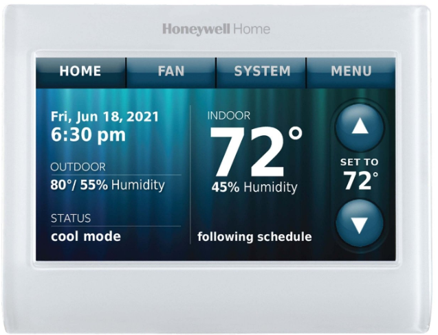
Honeywell TH9320WF Touchscreen Thermostat
Installation
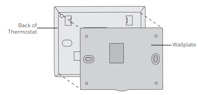
- Separate the wallplate from the thermostat.
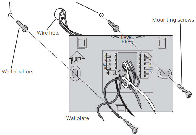
- Mount the wallplate as shown below.

- Drill 3/16″ holes for drywall. Drill 7/32″ holes for plaster.
Wiring
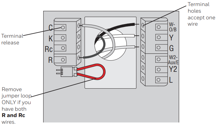
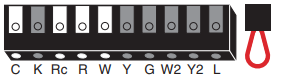
Terminal Designations
- C: Common wire from the secondary side of the cooling transformer (if 2 transformers).
- K: Optional C-wire adaptor.
- Rc: Cooling power. Connect to the secondary side of the cooling system transformer.
- R: Heating power. Connect to the secondary side of the heating system transformer.
- W-O/B: 1st stage heat relay. Or a changeover valve for heat pumps.
- Y: 1st stage compressor contactor.
- G: Fan relay.
- W2-Aux/E: 2nd stage heat relay. Or heat pump auxiliary/Emergency heat relay.
- Y2: 2nd stage compressor contactor.
- L: Heat pump system monitor. Y2 G Y L W2 MCR34825Jumper Loop, a plug with a wire loop used to connect the R to the Rc terminals. Leave the jumper loop in place in single transformer systems. Remove (unplug) the jumper loop in the two transformer systems.
Wiring guide — Conventional systems
- For the Honeywell TH9320WF thermostat installation, this thermostat requires a 24VAC common to power the unit. The K terminal is available for a C-wire adaptor (THP9045A1098).
- Straighten the wire. Using a pen tip to hold down the terminal, gently slide the wire into the terminal hole.
If you’re looking for another Wi-Fi-enabled model with similar touchscreen controls, check the Honeywell RTH9585WF Touchscreen Thermostat User Guide.
1H/1C System (1 transformer)

- Rc Power [1]
- R [R+Rc joined by jumper loop]
- Y Compressor contactor
- C 24VAC common
- W Heat relay
- G Fan relay
Heat-only System
- Rc Power [1]
- R [R+Rc joined by jumper loop]
- C 24VAC common
- W Heat relay
1H/1C System (2 transformers)
- Rc Power (cooling transformer) [1, 2]
- R Power (heating transformer) [1, 2]
- Y Compressor contactor
- C 24VAC common [3]
- W Heat relay
- G Fan relay
Heat-only System with Fan

- Rc Power [1]
- R [R+Rc joined by jumper loop]
- C 24VAC common
- W Heat relay
- G Fan relay
Cool-only System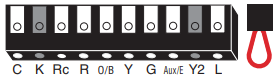
- Rc Power [1]
- R [R+Rc joined by jumper loop]
- Y Compressor contactor
- C 24VAC common
- G Fan relay
2H/2C System (1 transformer)
- Rc Power [1]
- R [R+Rc joined by jumper loop]
- Y Compressor contactor (stage 1)
- C 24VAC common
- W Heat relay (stage 1)
- G Fan relay
- W2 Heat relay (stage 2)
- Y2 Compressor contactor (stage 2)
2H/2C System (2 transformers)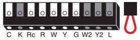
- Rc Power (cooling transformer) [1, 2]
- R Power (heating transformer) [1, 2]
- Y Compressor contactor (stage 1)
- C 24VAC common [3]
- W Heat relay (stage 1)
- G Fan relay
- W2 Heat relay (stage 2)
- Y2 Compressor contactor (stage 2)
Wire specifications
For Honeywell TH9320WF thermostat installation, use 18- to 22-gauge thermostat wire. Shielded cable is not required.
- Power supply. Provide disconnect means and overload protection as required.
- Remove jumper loop for 2-transformer systems.
- The common connection must come from the cooling transformer.
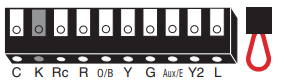
Wiring guide — heat pump systems
- This thermostat requires a 24VAC common to power the thermostat. The K terminal is available for
C-wire adaptor (THP9045A1098). - Straighten the wire. Using a pen tip to hold down the terminal, gently slide the wire into the terminal hole.
1H/1C Heat Pump System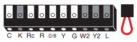
- Rc Power [1]
- R [R+Rc joined by jumper loop]
- Y Compressor contactor
- C 24VAC common
- O/B Changeover valve [7]
- G Fan relay\
2H/1C Heat Pump System
- Rc Power [1]
- R [R+Rc joined by jumper loop]
- Y Compressor contactor
- C 24VAC common
- O/B Changeover valve [2]
- G Fan relay
- Aux/E Auxiliary/Emergency heat relay
- L Heat pump system monitor
3H/2C Heat Pump System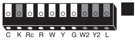
- Rc Power [1]
- R [R+Rc joined by jumper loop]
- Y Compressor contactor (stage 1)
- C 24VAC common
- O/B Changeover valve [2]
- G Fan relay
- Aux/E Auxiliary/Emergency heat relay
- Y2 Compressor contactor (stage 2)
- L Heat pump system monitor
Wire specifications
Use 18- to 22-gauge thermostat wire. Shielded cable is not required.
- Power supply. Provide disconnect means and overload protection as required.
- In Setup, set the changeover valve to O or B.
For users who prefer a simpler programmable option without Wi-Fi, see the Honeywell RTH8500 Series Programmable Thermostat Guide.
Initial setup
After completing the Honeywell TH9320WF thermostat installation, upon initial power-up or after being reset to factory defaults, the initial thermostat options (language, location, and system type) must be set to define the heating/cooling system. Other options can be customized later. Follow the prompts on the screen to select appropriate options.
- Touch the language you want the thermostat to display, then touch Next.
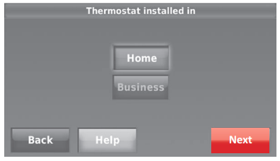
- Select Home or Business installation, then touch Next.
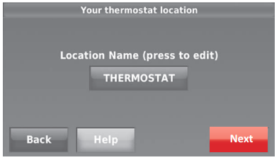
- Touch Next, or name the thermostat location—touch THERMOSTAT and follow the rest of the instructions.
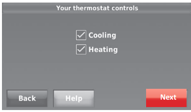
- Select what the thermostat will control and touch Next.
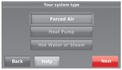
- Select the system type and touch Next. The system type determines other selections for completing the initial setup.
- Touch Next after making selections on each screen.
- Touch Done on the last screen. The thermostat displays an option to connect to the Wi-Fi network.

If you need a thermostat with advanced smart sensors and remote control, explore the Honeywell T9 Smart Sensor Thermostat Guide.
System setup
From the home screen, touch Menu > System Setup to modify the initial system setup.
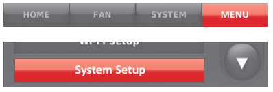
System Setup Options (MENU > System Setup)
- Languages
- English/Français/Español.
- Your system type
Select Forced Air (default), Heat Pump, Hot Water, or Steam. Each option offers different choices on the following screens. - Your forced air heating system type
Select how your forced air system is powered: Gas/Oil (default) or Electric. - The efficiency of your heating system
Select Standard Efficiency Forced Air (default) or High Efficiency Forced Air. - Your heating system type
If you selected Hot Water or Steam on “Your system type,” select the specific heating system here. - Number of cooling stages
Select 1 Stage (default) or 2 Stages. If you are unsure, note which wires are connected: ‘Y’ wire only (1 stage) or ‘Y’ and ‘Y2’. - Number of heating stages
Select 1 Stage (default) or 2 Stages. If you are unsure, note which wires are connected: ‘W’ wire only (1 stage) or ‘W’ and ‘W2’. - Your fan control
Select whether your thermostat (default) or heating system controls the fan. - Type of changeover valve
If you selected Heat Pump on “Your system type,“ select whether it uses a cooling changeover valve (default) or a heating changeover valve. - Number of heat pump compressor stages
Select 1 Stage (default) or 2 Stages. If you are unsure, note which wires are connected: ‘Y’ wire only (1 stage) or ‘Y’ and ‘Y2’. - Your backup heat
No or Yes (default)
Connecting to the Wi-Fi network
After completing the Honeywell TH9320WF thermostat installation and initial setup, walk the homeowner through connecting to a Wi-Fi network. Or, refer the homeowner to the User’s Guide so they can connect the thermostat to a Wi-Fi network at a later time.
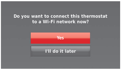
- Connect to the Winetwork.org
Touch Yes to connect the thermostat to the Wi-Fi network during the Honeywell TH9320WF thermostat installation process. The screen displays the message “Searching for wireless networks. Please wait…” after which it displays a list of all Wi-Fi networks it can find.
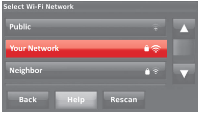
Select the Network
- 2a Touch the name of the homeowner’s network. The thermostat displays a password page.
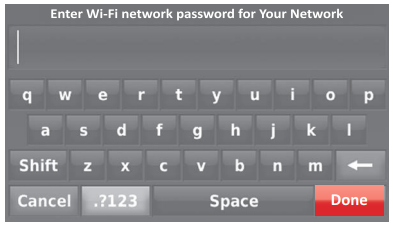
- 2b Using the keyboard, touch the characters that spell out the home network password.
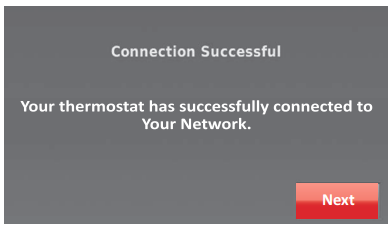
- 2c Touch Done. The thermostat displays “Connecting to your network. Please wait…” then shows a “Connection Successful” screen.
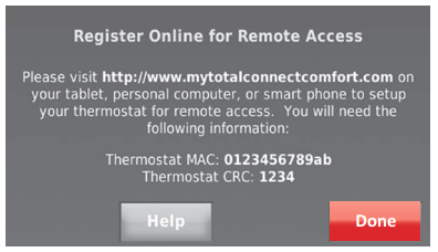
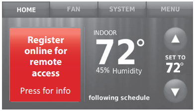
- 2d Touch Next to display the registration information screen.
- 2e Have the homeowner register the thermostat by going to https://www.mytotalconnectcomfort. com
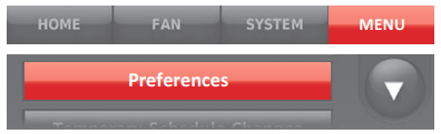
Note the Thermostat MAC and CRC; they’ll be needed during registration. Or, refer the homeowner to the User’s Guide. - Touch MENU. The thermostat displays a list of options.
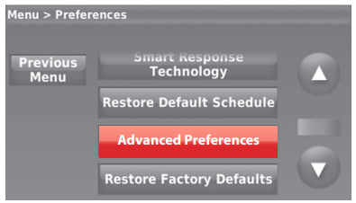
- Select Preferences > Advanced Preferences. The thermostat displays the first screen of options that you can change.
- On each screen, make changes as needed, then touch Next to display new options. Repeat this step until you have made all changes.
- When you have made all changes, press Done to save and exit.
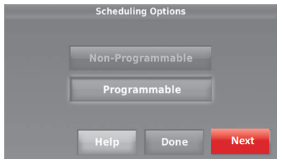
Scheduling Options
Select Non-programmable or Programmable. Programmable uses default or customized programming to automatically raise and lower temperature settings for different times of day.
- Temperature Indication
Scale Select Fahrenheit or Celsius. - Heating and Cooling
System Changeover: Select Manual or Automatic. - Number ofSchedulese
Perio: ds Select 2 Periods Per Day or 4 Periods Per Day. - Pre-occupancy Purge Duration
Select how long the fan will run before each occupied period: Off, 1, 2, or 3 hours. - Type of Override
Select Standard to maintain the programmed periods or Initiate Occupancy to use energy-saving settings until a user presses Start Occupancy. - Override Duration
Select how long to maintain the Honeywell TH9320WF temperature during an override: 1-10 hours or No Limit. - Early Recovery for Heating
Select No to begin recovery on schedule or Yes to ramp up temperature early. - Early Recovery for Cooling
Select No to begin recovery on schedule or Yes to ramp down temperature early. - Temperature Limits
Select the Minimum Cool and Maximum Heat Limit. - Keypad Lockout
Select Unlocked/Partially Locked/Locked. - Clock Format
Select 12-hour or 24-hour. - Daylight Saving Time
Select Off or On. If set to On, the system will automatically change the time/date to account for daylight saving. - Indoor Display Offsets
Select the number of degrees to offset the indoor temperature or the percentage to offset the indoor humidity.
Troubleshooting
If you have difficulty with your Honeywell TH9320WF thermostat installation or operation, please try the following suggestions. Most problems can be corrected quickly and easily.
- Check the circuit breaker and reset if necessary.
- Make sure the power switch on the heating and cooling system is on.
- Make sure the furnace door is closed securely.
- Make sure the C wire is connected.
- Check that the System Setup Honeywell TH9320WF screen “Your thermostat controls” or “Your system type” is set to match your heating and cooling equipment.
- Check that the System Setup screen “Your fan control” is set to match your heating equipment.
- The compressor protection feature is engaged. Wait 5 minutes for the system to restart safely, without damage to the compressor.
- Check your settings for the correct system setup. See “Type of changeover valve” on page 7.
- Touch the SYSTEM to set the system to Heat. Make sure the temperature is set higher than the Inside temperature.
- Touch the SYSTEM to set the system to Cool. Make sure the temperature is set lower than the Inside temperature.
- Check the circuit breaker and reset if necessary.
- Make sure the power switch on the heating and cooling system is on.
- Make sure the furnace door is closed securely.
- If “Wait” is displayed, the compressor protection timer is on. Wait 5 minutes for the system to restart safely, without damaging the compressor.
- Check that the System Setup screen “Your thermostat controls” or “Your system type” is set to match your heating and cooling equipment.
Specifications
Temperature Ranges
- Heat: 40° to 90°F (4.5° to 32°C)
- Cool: 50° to 99°F (10° to 37°C)
Operating Ambient Temperature
- 32° to 120°F (0° to 48.9°C)
Shipping Temperature
- -20° to 120°F (-28.9° to 48.9°C)
Operating Relative Humidity
- 5% to 90% (non-condensing)
Physical Dimensions
- 4-1/2″ W x 3-1/2″ H x 7/8” D
- (115 mm W x 88 mm H x 22 mm D)
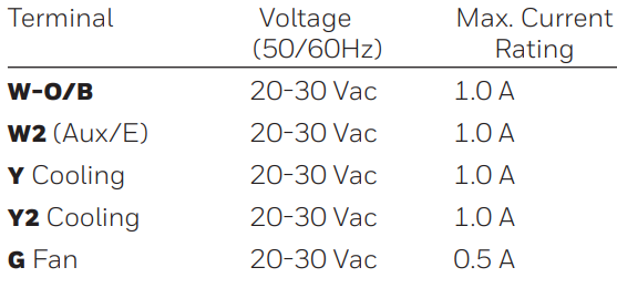
Electrical Ratings
Regulatory information
FCC REGULATIONS 47 CFR § 15.19 (a)(3)
This device complies with part 15 of the FCC Rules. Operations are subject to the following two conditions:
- This device may not cause harmful interference.
- This device must accept any interference received, including interference that may cause undesired operation.
47 CFR § 15.21 (USA only)
Changes or modifications not expressly approved by the party responsible for compliance could void the user’s authority to operate the equipment.
47 CFR § 15.105 (b)
- See https://customer.resideo.com/en-US/
- support/residential/codes-and-standards/
- FCC15105/Pages/default.aspx for additional FCC information for this product. IC REGULATIONS RSS GEN
- This device contains licence-exempt transmitter(s)/receiver(s) that comply with Innovation, Science and Economic Development Canada’s Honeywell TH9320WF licence-exempt RSS(s).
Operation is subject to the following two conditions
- This device may not cause interference.
- This device must accept any interference, Honeywell TH9320WF including interference that may cause undesired operation of the device.
- The operation of this equipment is subject to the following two conditions.
- This equipment or device may not cause harmful interference.
- This equipment or device must accept any interference, including interference that may cause undesired operation.
Another multi-stage programmable option worth checking is the Honeywell RTH7500 Series Thermostat Guide.
Customer Support
- Website: resideo.com
- Tell: 1-800-633-3991.
2019 Resideo Technologies, Inc.
FAQs
Q: What types of HVAC systems are compatible with the TH9320WF?
The majority of 24V heating and cooling systems, such as central air conditioning, heat pumps, and single- and multi-stage furnaces, are compatible with the TH9320WF. It is incompatible with millivolt heating systems and line-voltage (120/240V) systems.
Q: Does this thermostat require a C-wire for installation?
Indeed. To supply constant power for the touchscreen and Wi-Fi connectivity, the TH9320WF needs a C-wire, or common wire. A C-wire adaptor or expert installation is advised if your system lacks a C-wire.
Q: Can I install the thermostat myself, or do I need a professional?
With the help of the provided instructions, homeowners with a basic understanding of electrical work may install the thermostat themselves.
Q: What tools do I need for installation?
A screwdriver, wire stripper, level, and drill (optional for wall anchors) are typical instruments needed. Screws and wall anchors are included in the thermostat’s installation kit.
Q: How do I connect the thermostat to Wi-Fi?
Once the thermostat has been wired and powered on, choose Wi-Fi Setup from the touchscreen. To connect it to your home network, use the Honeywell Home app and follow the detailed instructions.
Q: Can I retain my existing thermostat schedule when installing the TH9320WF?
No, new schedules will need to be set up to install the TH9320WF. Using the Honeywell Home app or the touchscreen, you can make personalised schedules.
Q: What if my thermostat won’t power on after installation?
Make sure that the HVAC system is powered on and that the C-wire is connected correctly. Verify that every wire is firmly fastened to the terminal block. Get in touch with Honeywell assistance if it still won’t turn on.
4 Comments
Pingback: Honeywell RTH9585WF Thermostat Manual | Setup & Wi-Fi Guide
Pingback: Honeywell RTH2410 Programmable Thermostat | Manual & Setup
Pingback: Honeywell RTH8500 Series Programmable Thermostat Guide
Pingback: Honeywell Thermostat Manual | Step-by-Step Setup & Programming Guide – Storium