

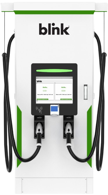
BLINK DCFC 160kW Fast Charging Station
Safety Instructions
This unit is a high-powered electrical device and can be hazardous if improperly installed, serviced, or operated. Failure to follow procedures in this manual could result in hazards to personnel and/or damage to the equipment and related infrastructure. In addition, the installation, service, and maintenance need to comply with local codes and the Authority Having Jurisdiction (AHJ).
The symbols used are international icons used to depict various levels of caution when installing, servicing, or maintaining the equipment. The same symbols will also appear on the equipment for identifying caution levels required when accessing certain areas of the charger.
| TP5-160-480-1 | Max Voltage: 1000VDC; Connectors: CCS1 and CHAdeMO |
| TP5-160-480-2 | Max Voltage: 1000VDC: Connectors: CCS1 and CCS1 |
| HPC-160-480-1 | Max Voltage: 1000VDC: Connectors: Liquid Cooled CCS1 and CHAdeMO |
| HPC-160-480-2 | Max Voltage:1000VDC: Connectors Dual Liquid Cooled CCS1 |
| HPC-160-480-3 | Max Voltage: 1000VDC: Connectors: Liquid Cooled CCS1 and Liquid Cooled NACS |
| HPC-160-480-4 | Max Voltage: 1000VDC: Connectors: Dual Liquid Cooled NACS |
| TP5-160-480-2-300 | Max Voltage:1000VDC: Connectors: Dual CCS1 300A (Nominal) & 350A (Peak) |
| TP5-160-480-3 | Max Voltage:1000VDC: Connectors: CCS1 and NACS |
| TP5-160-480-4 | Max Voltage:1000VDC: Connectors: NACS and NACS |
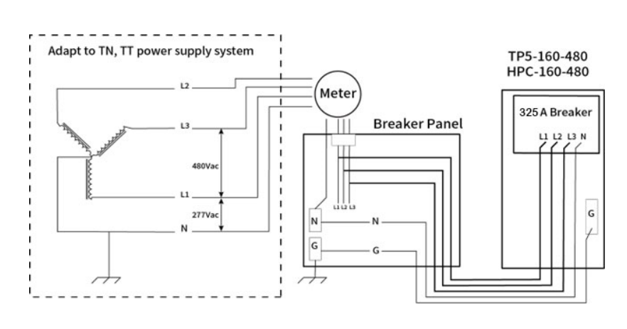
Grid System
Installation Overview
| Electrical Input Requirements | Input voltage: 480Y VAC (3 Phase + Neutral + Earth), 60Hz |
| Full Load Amperage: 215 Amps (At Rated power) | |
| Breaker Capacity: 270 Amps | |
| Location | This charging station has 4 doors, i.e., Front, Rear, Left, and Right. Clear a 35” distance on the front and rear sides and 24” on the left and right sides of a charger to be maintained for air circulation for cooling and opening the panel for maintenance. |
| HPC-160-480 Charger Dimensions (L X D X H): 43.07”x 36.97”x 81.30” TP5-160-480 Charger Dimensions (L X D X H): 39.96”x 29.52”x 73.42” | |
| Mounting Pad | Mounting pad shall be of concrete cement with approximate dimensions Length 41.3″, Width 41.7″, Height 29.6″, to accommodate the weight and dimensions of the base. Place the charger on the concrete mounting pad with anchor studs using lock washers and nuts. |
| For relocation/lifting – A Forklift can be used; provision has been made for this. |
| Barricade (Bollards) | Suitable bollards should be provisioned to restrict the approach of EVs to the charger. EV shall be in accordance with local code. |
| Cables | Input Cables must be Copper (3P+N). Flexible copper is preferred. Please see the table below in the next section for the cable gauge. |
| Grounding | Reliable protective grounding must be provided. It is recommended to have a separate dedicated ground exclusively for the charger, considering safety aspects. The ground resistance should be less than or equal to 4Ω. Copper cable in accordance with NEC shall be used to connect the charger housing to the external ground. |
| Breaker | Breaker (3P+N) with suitable current capacity depending on the charger rating to be provided. This shall be in accordance with NEC, typically 1.25 X Full Load Amperage. |
| Miscellaneous | Copper lugs (Flat type) for the input cable and earth cable should be provided based on the size of the cable. |
Cable Gauge
| Capacity | FLA(Amps) | Breaker(Amps) | AWG |
| 30kW | 40 | 50 | 8 |
| 60kW | 80 | 100 | 2 |
| 120kW | 160 | 200 | 3/0 |
| 160kW | 215 | 270 | 300MCM |
| 180kW | 240 | 300 | 350MCM |
| 200kW | 265 | 335 | 400MCM |
| 240kW | 320 | 400 | 600MCM |
| 300kW | 400 | 500 | 900MCM |
| 360kW | 480 | 600 | 1500MCM |
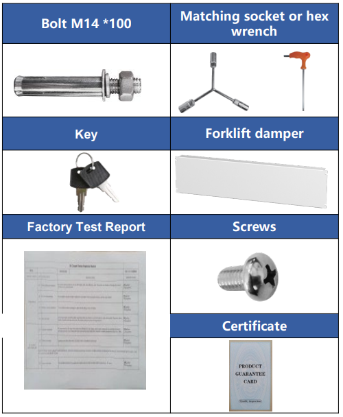
Box Content
| Item | Quantity |
| Charger | 1 |
| Bolt M14 *100 | 6 |
| Key | 2 |
| Factory Test Report | 1 |
| Matching socket or hex wrench; Match according to the molded ase circuit breaker model. | 1 |
| Forklift damper | 2 |
| Screws M5 *8 | 8 |
| Certificate | 1 |
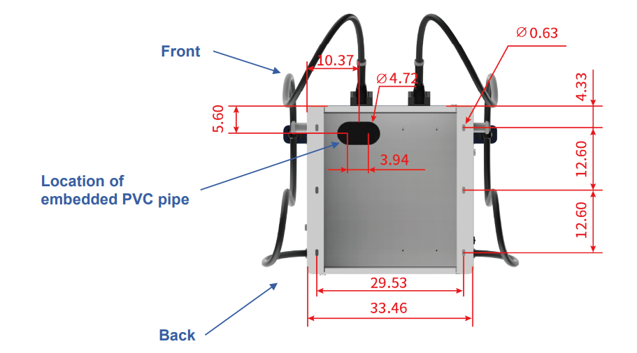
Outline Of Drawing (HPC -160 -480)
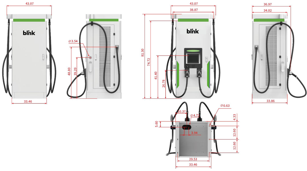
Before making the concrete pad, determine the position of the pre-embedded PVC pipe according to the position shown in the figure to facilitate later wiring.
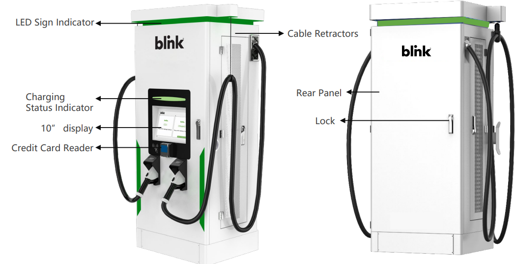
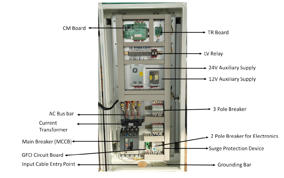
Atation Anatomy
Mechanical Installation (HPC-160-480)
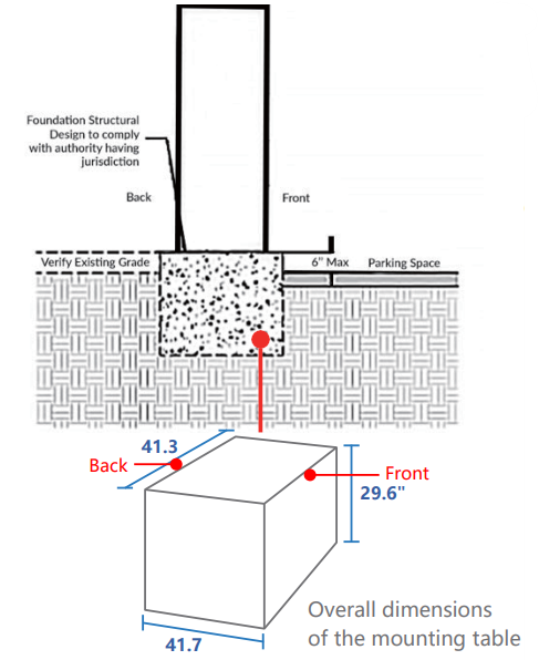
CONCRETE PAD
A concrete pad using 3,000 to 4,000 psi concrete should be used. Electrical for AC power should be positioned such that it exits the concrete pad at the Main AC Power Line Opening.
- When making the installation platform, a PVC pipe with a diameter of 100mm is pre-buried, and steel wires are reserved in the PVC pipe for the convenience of wiring.
- The reserved position of the PVC pipe corresponds to the position of the cable inlet at the bottom of the charging pile.
- The dimensions of the concrete foundation will need to be determined according to the local jurisdiction. The reference foundation is 23.6″ deep below ground.
- Foundation fabrication uses steel bars in accordance with relevant standards. Recommended 5/8″ threaded rebar.
- The concrete platform should be 6″ above ground; any more than 6″ will cause the charger to control above the ADA compliance maximum, and may cause the inspection to fail, and the foundation may need to be lowered to meet ADA guidelines.
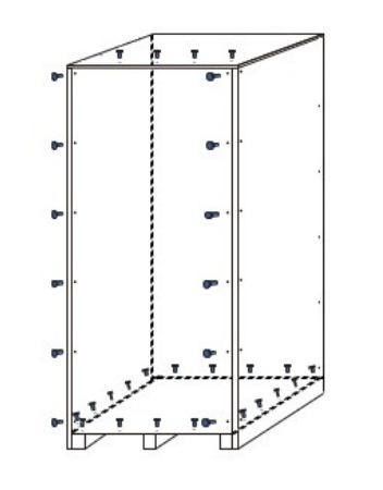
Unpack
- Remove the screws on the front panel, the top front, and all the bottom screws.
- Untie the straps that fix the charging station and remove the vacuum
- select Authorization/Payment MethodCHARGER SETTINGS
| S.NO | PARAMETERS | VALUE | REMARKS |
| 1 | NETWORK | ETH | Ethernet-DO NOT CHANGE |
| 2 | NETCFGFILE | /etc/network/interfaces | Path- DO NOT CHANGE |
| 3 | WLANCONF | /home/guest/wpa_supplicant. conf | Path-DO NOT CHANGE |
| 4 | DEVICEIP | 192.168.2.13 | IP Address of Device |
| 5 | DEVICEGATEWAY | 192.168.2.1 | IP Address of Gateway |
| 6 | DEVICENETMASK | 255.255.255.0 | IP Address of mask |
| 7 | SERVERURL | ws://exampleserver.com:9100 /ocpp/202006051001 | Server Address of OCPP |
| 8 | DEVICEID | 2020060510 | Device ID |
| 9 | AUTHORIZATIONKEY | 4F43415F4F4354545F61646D 696E5F74657374 | Authentication code of the Server login |
| 10 | CHARGEPOINTVENDOR | Blink | ID of Operator |
| 11 | CHARGEPOINTMODEL | DC | Charger Type- DO NOT CHANGE |
| 12 | ADPATH | / | NA |
| 13 | QRCODENAME | / | NA |
| S.NO | PARAMETERS | VALUE | REMARKS |
| 14 | LANG | en | Path – DO NOT CHANGE |
| 15 | MODE | / | NA |
| 16 | APN | / | NA |
| 17 | CHARGINGPIC | / | NA |
| 18 | IDELPIC | / | NA |
| 19 | LCM | lcm:1=/dev/ttyS4 | Path – DO NOT CHANGE |
| 20 | LCMENCODETYPE | UNICODE | Encode –DO NOT CHANGE |
| 21 | LCMPASSWD | XXX | Password for access |
| 22 | RFID | RFID0=/dev/ttyS1 | Communication Interface of RFID |
| 23 | PLUGDCNUMBER | 2 | The quantity of guns |
| 24 | PLUG1 | DIN1DC1:3=/dev/ttyS0 | Path – DO NOT CHANGE |
| 25 | PLUG2 | DIN1DC2:3=/dev/ttyS0 | Path – DO NOT CHANGE |
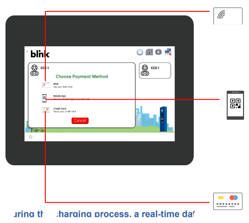
Rfid Card
- The charger display will provide options to select
Authorization/Payment Method. - Swipe the RFID Card.
- The charging session will begin within 60 seconds.
- To stop the charging – Swipe the same RFID card again
Or use the STOP button on the screen.
QR CODE /MOBILE APP
- The charger display will provide options to select the Authorization/Payment Method.
- Scan the OR code or start charging.g fromMobileeThe l
- charging session will begin within 60 seconds..
- To stop the charging – Stop from the Mobile App or use the STOP button on the screen
CREDIT The charger
- ger display will provide options to select the Authorization/Payment Method.
- Authorize your credit card. Make sure you have enough balance on the card to charge..
- The charging session will begin within 60 seconds..
- Charging will automatically stop after 100% h, use the Sbutton on the screen.
During the charging process, a real-time data output of the charging process appears on the screen. At any point in time, a charging session can be stopped using the Stop button on the screen or the Emergency Stop button for emergency uses ONLY.
Maintainance & Sevice
Each of the capacitors in this device has a high voltage for a time after shutting off the input power supply. Allow 1 minute after powering down before servicing internal components.
Items
Perform periodic checks every 3 to 6 months based on the site conditions and the usage of the charging station.
- Check the input voltage and ensure it is within the acceptable limits.
- Check the Ground / Earth resistance and ensure the BLINK DCFC 160kW Fast Charging Station is within the acceptable limits..
- Clean the Air Filter periodically.
- Make sure that Power Module lights are solid green ONLY.
- Ensure the charging cables are not worn out and gun pins are clean.
- Make sure all the air-cooling fans of are BLINK DCFC 160kW Fast Charging Station are working normally
Visual Check
- Check for abnormal sounds from running fans and power units.
- If there is any abnormal sound, please don’t make assumptions! Call us for further assistance.
- Check for abnormal odor, changes in inner materials, corrosion, anomalies in appearance, etc., in
this device. - If there are any anomalies, please don’t make assumptions; call us for further assistance!
- Check for dust and dirt in this device regularly.
- Please pay extra attention while using the vacuum cleaner; it should not apply pressure on the control boards or any components.
Replacement Of Component
To prevent the device from failure due to worn-out components, it is necessary to replace the components
before they reach the end of their lifespan. Use the following BLINK DCFC 160kW Fast Charging Station replacement intervals as a guideline for the estimate of the total running time. Please don’t make assumptions, call us! For further assistance when you replace the parts.
- Intake and exhaust air filters (if present): Approximately three (3) years. The period depends upon the site conditions.
- Please keep in mind that the replacement interval of each part can vary depending on, for example, the usage environment of the device.
Error Codes
| ERROR | DESCRIPTION | POSSIBLE SOLUTION |
| ERROR FLAG 0 | Lightning protection device failure | Check the SPD and GFCI circuit |
| ERROR FLAG 1 | Insulation detection abnormal | The insulation check on the EV has failed. Please try to charge a different EV. |
| ERROR FLAG 2 | Abnormal communication between Insulation Monitor and Main Control Board (CM) | Please check the connection between the IM and CM boards. Check the LED lights on the CM and I.M |
| ERROR FLAG 3 | Abnormal communication between the TR board and the CM board | Please check the connection between the TR and CM boards. Check the LED lights on the CM and TR |
| ERROR FLAG 4 | Electronic lock failure | Possible failure of the gun to lock on the EV or the 24V supply voltage |
| ERROR FLAG 5 | Internal use | Reserved |
| ERROR FLAG 6 | Abnormal communication between DC meter and Main Control Board (CM) | Please check the connection between the DC and CM boards. Check the LED lights on the CM and communication lines of the DC meter. |
Troubleshooting
| FAULT TYPE | SOLUTION |
| IP address communication Failure or Server Communication Failure | Please check the parameter settings interface IP address information, such as the corresponding IP address is not correct, please re-enter the address, restart the charging station |
| AC input overvoltage / undervoltage | Please check the AC input side of the voltage is too high or too low, excluding the input exception if there is a fault, and then check that the parameters set in the interface set the threshold are correct |
| DC output overvoltage/overcurrent | Please check whether the output voltage and current are within the range of parameter settings. If not, please check whether the output voltage, current are too high, or whether the parameter setting is reasonable.. |
| Card reader failure | The card reader is incorrectly wired, or the card reader is disabled. |
| Insulation fault | Please check whether the DC bus insulation is normal. |
| Monitoring board communication failure | Check whether the monitoring board communication line is correct |
| Charging gun connection failure | The charging gun connection disconnected. Please check whether the charging gun is connected properly. |
Customer Responsibilities
- To operate the charge station with the required protective devices, such as MCBs and switches, and with proper cables installed.
- To write an emergency plan that instructs people on what to do in case of an emergency.
- To locate and prepare the site as per the instructions laid out in this document.
- To make sure that there is sufficient space around the charger to carry out any regular maintenance work.
- To appoint a trained person(s) responsible for the safe maintenance/service of the charge station.
- Neither Blink nor any of its affiliates shall be liable to the operator/owner/customer of this product or third parties for damages, losses, costs, or expenses incurred by as a result of: an accident, misuse or abuse of this product or unauthorized modifications, repairs or alterations to this product, or failure to strictly comply Blink’s’s operating and maintenance instructions.
Warranty & Service Plan
Blink DC chargers come with a 2-year parts-only standard warranty (actual warranty length is subject to sales contractHservice plans that cover parts and BLINK DCFC 160kW Fast Charging Station labor for an additional add-on fee.
Warranty
LIMITED WARRANTY: Subject to the exclusions from warranty coverage set forth below, Blink warrants that the Product will be free from any defects in materials and/or workmanship (the Limited Warranty)
for a period of two years after 30 days from the date of shipment or from the date of the initial installation, whichever is earlier (the Warranty Period).
If the Product becomes defective in breach of the Limited Warranty, Blink will, upon written notice of the defect received during the Warranty Period, either repair or replace, at the choice of Blink, the Product if it proves to be defective. Blink will also pay
For shipping charges for the failed part. If the returned part has not failed, the customer will pay for shipping charges for the replacement part and the associated returned part. Under this guarantee,
The BLINK DCFC 160kW Fast Charging Station warranty will not include removal costs, reinstallation costs, loss of charging station revenue, nor loss or damage of any kind whatsoever, whether incidental, consequential, or otherwise.
Exclusions
- Damages due to normal wear and tear to charging cords, connectors, LCD/LED display, and Touch
Screen, or any product alteration or modification, misuse, abuse, accident, vandalism, acts of nature,
power surges, or use of software, parts, or supplies not supplied by Blink, and causes other than
manufacturing defects not covered by the warranty. - Force Majeure – any occurrence or extraordinary event or circumstance beyond the control of Blink
flooding, earthquake, volcanic eruption, etc.), or other natural forces, including high input voltage
from generators or lightning strikes or acts of nature, or other causes. - Any alteration or modification of the Product in any way not approved in writing by Blink..
- Damage caused by accidents, extreme power surges, and extreme electromagnetic fields.
- Use of the Product with software, interfacing, parts, or supplies not supplied by Blink.
- Blink disclaims any liability for damage to product, property, or personal injury resulting in whole or in part from improper installation, maintenance, or use that is not in accordance with Blink installation and maintenance procedures.
Customer Service
This document is the Property of Blink and should not be copied, reproduced, or ordered on he bbasismof oromanufacturing manufacturing apparatus without the written permission of Blink. For any support on installation and commissioning.
- Ph: 888-998-2546
- Timings: 12 hours from 9:00 AM to 1:00 AM
- Website: support@blinkcharging.com
FAQs
What types of vehicles are compatible with the BLINK DCFC 160kW station?
Depending on the port fitted, the station can support any EV with CHAdeMO or CCS (Combined Charging System) connectors. Before using your EV, make sure it is compatible with charging.
How fast will my vehicle charge?
The maximum DC fast charging capacity of your EV, battery level, and outside temperature all affect charging speed. Most compatible EVs can reach 80% charge in 20–40 minutes thanks to the station’s 160 kW output.
Do I need an account to use the station?
Indeed. To start charging, you must sign up for BLINK Charging using the app or RFID card. Depending on operator settings, certain stations might allow guest sessions.
Is the station compatible with Tesla vehicles?
Yes, in areas that support CCS, either directly or through a Tesla CCS adaptor (for North America).
What is the operating temperature range?
Between -30°C and 50°C (-22°F and 122°F), the station can function safely. High temperatures may momentarily slow down charging.
Can the station charge vehicles with smaller batteries efficiently?
Indeed. In order to control charging power and provide the best speed without causing battery damage, the station talks to the EV.