
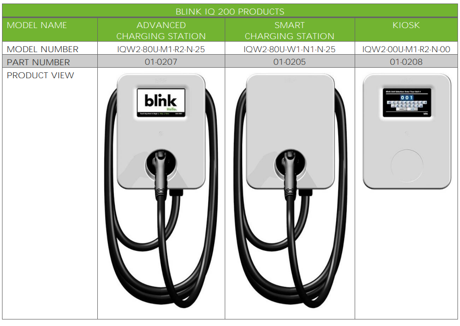
Blink IQ 200 Level 2 AC EVSE Charging Station
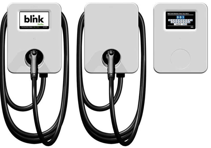
Product Overview
Conduit & Breaker Size Guide
| All Specifications are Per Charging Station or Port | ||||||
| Typical Circuit Breaker (CB)3 | Typical Wire Specs3 | Typical Conduit Size 3 | Blink IQ 200 Enclosure Input Conduit Size | Notes / Assumptions | ||
| 15A | Two #12AWG Wires (Line) One #12AWG Wire (Ground) | 1/2″ | -Way Distance | |||
| 20A | Two #10AWG Wires (Line) One #12AWG Wire (Ground) | 3/4″ | -Way Distance | |||
| 30A | Two #8AWG Wires (Line) One #10AWG Wire (Ground) | 3/4″ | -Way Distance | |||
| 40A | Two #8AWG Wires (Line) One #10AWG Wire (Ground) | 3/4″ | -Way Distance | |||
| 50A | Two #6AWG Wires (Line) One #8AWG Wire (Ground) | 3/4″ | -Way Distance | |||
| 80A | Two #4AWG Wires (Line) One #8AWG Wire (Ground) | One-Way Distance | ||||
| 90A | Two #3AWG Wires (Line) One #8AWG Wire (Ground) | -Way Distance | ||||
| 100A | Two #2AWG Wires (Line) One #8AWG Wire (Ground) | -Way Distance | ||||
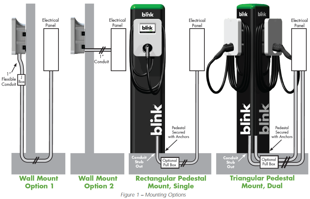
Mounting Options
Installation
Tools Required for Installation
| Tool | Applicable Models | Supplier Name | Supplier Part # |
| Security Torx T20 L-Driver | All Product Models | Blink | Included in Product Box |
| Security Torx T20 Driver | All Product Models | Commercially Available | Commercially Available |
| Wire Cutters | All Product Models | Commercially Available | Commercially Available |
| Wire Strippers | All Product Models | Commercially Available | Commercially Available |
| Channellock Pliers | All Product Models | Commercially Available | Commercially Available |
| Torque Wrench | All Product Models | Commercially Available | Commercially Available |
| Drill | All Product Models | Commercially Available | Commercially Available |
| Drill Bits | All Product Models | Commercially Available | Commercially Available |
| Slotted Screwdriver | All Product Models | Commercially Available | Commercially Available |
| P2 Phillips Screwdriver | Kiosk Model | Commercially Available | Commercially Available |
| P3 Phillips Screwdriver | Advanced & Smart Models | Commercially Available | Commercially Available |
| Crimpers, 12-14 AWG | Kiosk Model | Commercially Available | Commercially Available |
| Crimpers, 8-4/0 AWG | Advanced & Smart Models | Greenlee | K09-2GL |
Parts Required for Installation
| Part | QTY | Applicable Models | Supplier |
| Product | 1 | All Product Models | Blink, Included in Product Box |
| Mounting Bracket | 1 | All Product Models | Blink, Included in Product Box |
| Mounting Bolts To Secure the EVSE to the Mounting Bracket | 4 | All Product Models | Blink, Included in Product Box |
| Ring Terminal, 2 AWG, Power Terminals | 2 | Advanced & Smart Models | Blink, Included in Product Box |
| Ring Terminal, 8 AWG, Power Terminals | 2 | Advanced & Smart Models | Blink, Included in Product Box |
| Ring Terminal, 8 AWG, Ground Terminal | 1 | Advanced & Smart Models | Blink, Included in Product Box |
| Ring Terminal Insulators, Vinyl End Caps | 5 | Advanced & Smart Models | Blink, Included in Product Box |
| Wire, Copper | As Needed | Commercially Available | Commercially Available |
| Wall Mount Only | 2 | Commercially Available | Commercially Available |
| Wall Mount Only | 4 | Commercially Available | Commercially Available |
| Wall Mount Only | 1 | Commercially Available | Commercially Available |
| Wall Mount Only | As Needed | Commercially Available | Commercially Available |
Installation Procedure
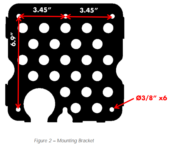
- Open the Blink Product box and locate the mounting bracket.

- Drill holes in the wall or mounting surface for the mounting bolts.
- Secure the mounting bracket to the wall or mounting surface with appropriate fasteners as follows
- For metal construction, use 5/16″ screws or bolts.
- For wood construction, use 5/16″ lag bolts.
- For masonry walls, use 5/16″ expansion anchors.
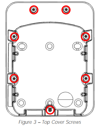
- Remove the top cover from the Blink Product using a Security T20 driver to loosen the 7 screws.
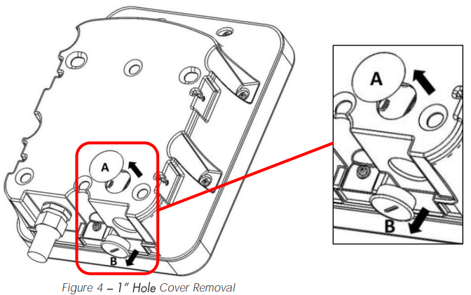
- Remove the appropriate 1″ hole cover (A or B) based on the desired conduit entry point.
- Attach the 1″ conduit (with wire) to the enclosure using the appropriate 1″ conduit fitting.
- Choose the appropriate conduit and wire based on Table 1 – Conduit and Breaker Size Guide and in accordance with all applicable state, local, and national electrical codes and standards. Use conductor type other than RHH, RHW and RHW-2.
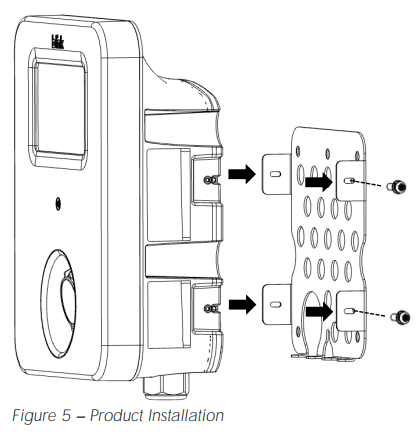
- Attach the product to the mounting bracket using the 4 included mounting bolts and a Security T20 Driver using a torque force of 13 Inch-Pounds (1.5 Newton Meters).
- Using the appropriate wire stripping tool and crimping tool specified in Table 2 Tools Required for Installation, crimp the included ring terminals to the wires.
- Slide the included Vinyl End Caps over the crimped ring terminals.
- Remove the clear plastic cover from the terminal block.
- Attach the crimped ring terminals to the terminal block inside the Blink Product.
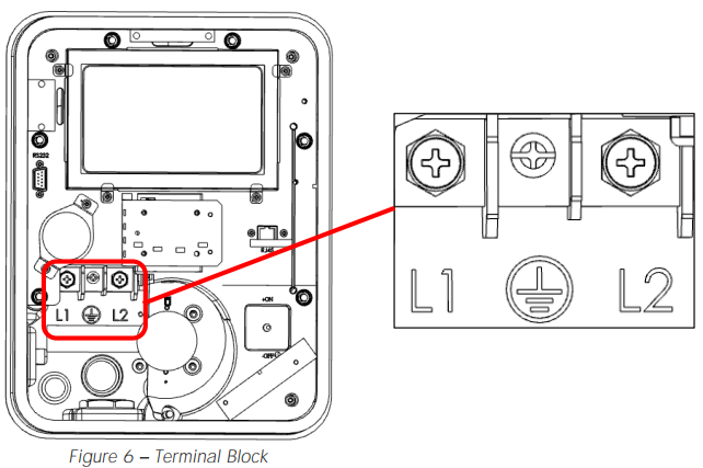
- Ensure that the terminal block bolts are tightened using the following torque specifications
Advanced and Smart Models
- L1 and L2: 70 Inch-Pounds (8 Newton-Meters)
- Ground: 26 Inch-Pounds (3 Newton-Meters) Blink IQ 200 Level 2 AC EVSE Charging Station Kiosk Model
- L1 and L2: 7 Inch-Pounds (0.8 Newton Meters)
- Ground: 7 Inch-Pounds (0.8 Newton Meters)
- Re-attach the clear plastic cover to the terminal block.
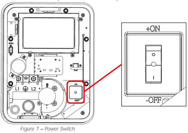
- Turn the power switch from the “OFF” position to the “ON” position.
- Re-attach the top cover to the Blink Product using a Security T20 Driver and a torque force of 13 Inch-Pounds (1.5 Newton Meters).
- Apply power to the Blink Product.
- If applicable, coil the charge cable around the Blink Blink IQ 200 Level 2 AC EVSE Charging Station Product and attach the charging connector to the holster.

Setup Instruction
Web Portal Access
- Contact the Blink Network Support Center at 1-888-998-BLINK (2546) to obtain the Wi-Fi password AND the Web Portal password.
- Using a computer, a tablet, or a smartphone that supports Wi-Fi, browse for available networks.
- Connect to the Blink Produ-Fi network by selecting the SSID (Wi-Fi Network Name) which corresponds with the unit’s serial number (displayed on the left side of the unit).
- The format of the Wi-Fi Network name will be Blink IQ 200 Level 2 AC EVSE Charging Station be Blink-SerialNumber
- Example: Blink-L1-0207-1638-123456
- Enter the Wi-Fi password and connect to the Wi-Fi network.
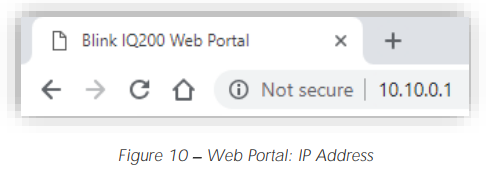
- Open a web browser (such as Google Chrome, Mozilla Firefox, Safari, etc.) and navigate to the following IP address: 10.10.0.1
- In the User Name field, enter admin.
- In the Password field, enter the password that you received from the Blink Network Support Center.
Changing the Maximum Output
- If a circuit breaker is upgraded at a later time, the Blink Product must be re-commissioned and the maximum output (charging) current must be adjusted at that time by authorized personnel.
- On the Configuration page of the unit, select the Station Settings tab.
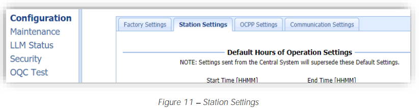
- On the Station Settings tab, enter the Maximum Charging Current in the Max Amperage FW Setting field. The amperage value should be a number that is in the following range: 12.0 to 80.0.
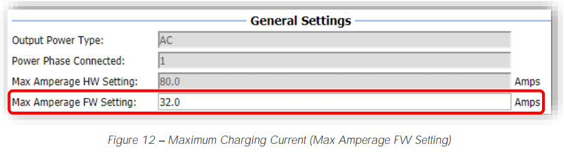
| Circuit Breaker Size | 15A | 20A | 30A | 40A | 50A | 80A | 90A | 100A |
| Max Amperage FW Setting | 12.0 | 16.0 | 24.0 | 32.0 | 40.0 | 64.0 | 72.0 | 80.0 |
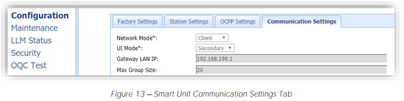
Connecting a Smart Unit
- On the Configuration page of the Smart Unit, select the Communication Settings tab.
- On the Communication Settings tab, enter the Serial Number of the Kiosk in the Gateway Serial Number field. The Serial Number of the Kiosk can be found on the product label on the left side of the unit.
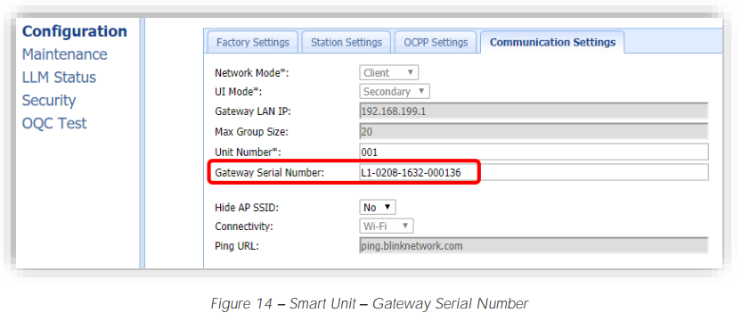
- Select the Apply button at the bottom of the page Repeat steps 7.1.2 through 7.3.3 for each Smart unit that needs to be connected to the Kiosk.
Operating Instructions
Starting a Charge Session
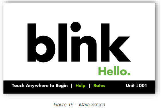
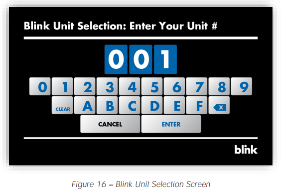
- Release the charging connector from the holster and connect it to the EV. Touch the Main Screen to begin the authorization process.
- Kiosk Only: Enter the Unit # of the charging station then touch ENTER. The Unit # of a charging station is located on a label on the right side of the unit.
- Initiate a charge session using one f the following authorization methods:
- RFID Card
- Remote Start Command (Using a Mobile App)
- Blink Code (If Applicable)
- Smart Credit Card / Apple Pay / Google Pay (May not be included in the initial product offering)
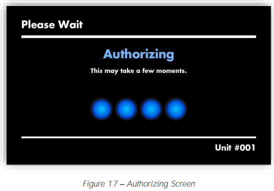
- The Authorizing screen will appear while the unit communicates with the Central System
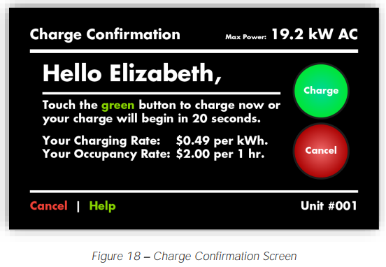
- Once the Charge Confirmation screen appears, select the Charge button.
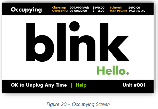
- While the EV is being charged, the Charging screen will be displayed.
- While the EV is connected but not being charged, Blink IQ 200 Level 2 AC EVSE Charging Station the Occupying screen will be displayed.

Stopping a Charge Session
- Disconnect the charging connector from the EV at any time to stop the charge session.
- Once the session has been stopped, the Cost Summary screen will appear (if applicable).
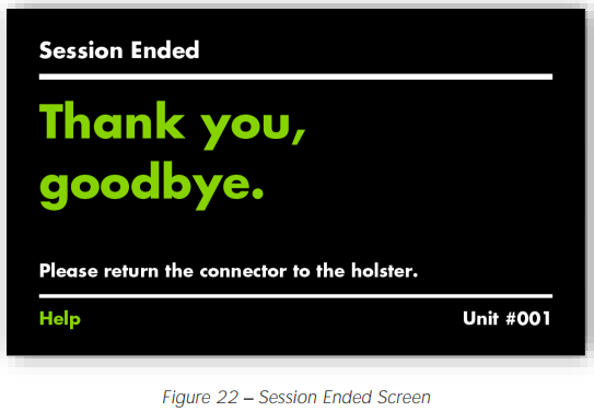
- Touch the CLOSE button or wait until the screen times out. The Se sion Ended screen will appear.
- Next, the Main Screen will appear.

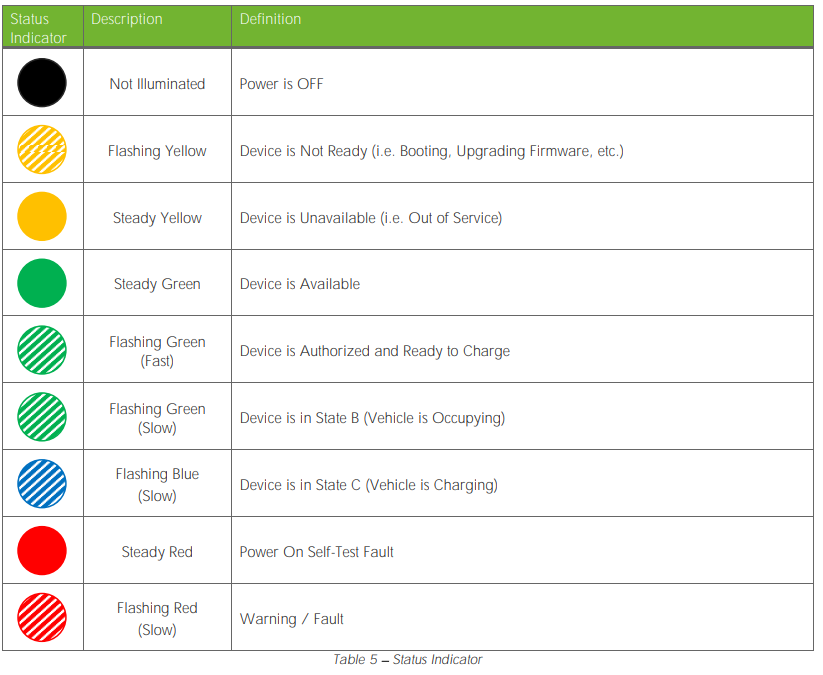
Status Indicator
Configuration
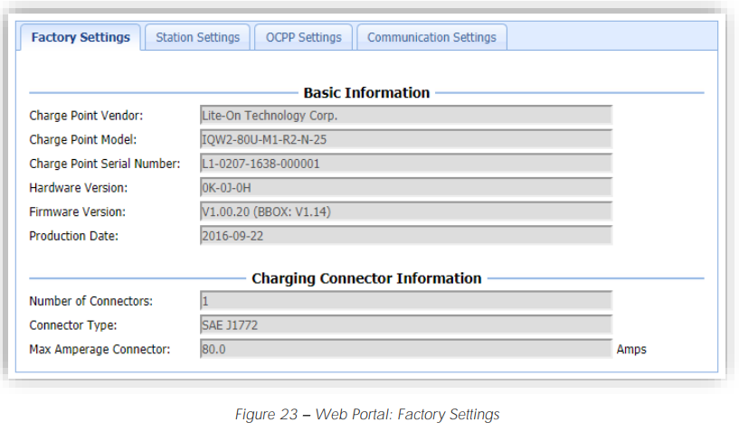
Factory Settings
- Initially, the Factory Settings tab will appear, whichBlink IQ 200 Level 2 AC EVSE Charging Station reflects the items which have been configured at the factory.
- The following table provides an overview of each item.
| Configuration Item | Description |
| Charge Point Vendor | The name of the Blink Product Vendor. |
| Charge Point Model | The Model Number of the Blink Product. |
| Charge Point Serial Number | The unique Serial Number of the Blink Product. |
| Hardware Version | The Hardware Version of the Blink Product. |
| Firmware Version | The Firmware Version of the Blink Product. |
| Production Date | The Production Date of the Blink Product. |
| Number of Connectors | The number of connectors associated with the Blink Product. |
| Connector Type | The type of charge connector. |
| Max. Amperage Connector | The maximum current output for the Blink Product. |
Station Settings
| Configuration Item | Description |
| Default Hours of Operation Settings | |
| Default Hours of Operation Settings | The default Hours of Operation. Settings sent from the Central System will supersede these default settings. |
| Warning Settings | |
| Temperature Low | The value in Celsius at which the charger will send a low temperature warning. |
| Temperature High | The value in Celsius at which the charger will send a high temperature warning. |
| Voltage Low | The value at which the charger will send a low voltage warning. |
| Voltage High | The value at which the charger will send a high voltage warning. |
| General Settings | |
| Output Power Type | The output power type of the Blink Product. |
| Power Phase Connected | The power phase configuration of the Blink Product. |
| Max Amperage HW Setting | The maximum current output for the Blink Product. |
| Max Amperage FW Setting | The configurable (and de-ratable) maximum current for the Blink Product. |
| PWM Amperage | The amperage used by the PWM interface connected to the EV. |
| Real Amperage | The real-time measured amperage. |
| Cold Load Pickup Max Delay | The maximum delay (in seconds) before a charging session is resumed after power is reapplied after a power outage. The value is configurable between 120 and 720 seconds. |
OCPP Settings
| Configuration Item | Description |
| Remote Service Settings | |
| Remote Service Type | Specifies the protocol that the Blink Product will use to communicate with a Central System. |
| Service Settings | |
| Charge Point ID | The identity of the charger as known by the Central System. This setting is typically the Charge Point Serial Number. |
| Protocol Name | The protocol that the Blink Product will use to communicate with a Central System. |
| Central System URL | The URL of the Central System. |
| Basic Auth ID | The ID for Basic authentication regarding HTTPS (SSL/TLS) connections. |
| Basic Auth Password | The password for Basic authentication regarding HTTPS (SSL/TLS) connections. |
| FTP Server Username | The ID that the Blink Product will use to connect to an FTP server which contains firmware packages and ad loops. |
| FTP Server Password | The password that the Blink Product will use to connect to an FTP server which contains firmware packages and ad loops. |
| Message Transport Layer | Indicates whether WS (WebSocket protocol over http) or WSS (WebSocket protocol over https) is used. |
| WebSocket Ping Interval | The interval (in seconds) between WebSocket pings. |
| Boot Notification Interval | The interval (in seconds) between bootNotification retries. |
| Boot Notification Retries | The maximum number of bootNotification retries. A setting of -1 indicates an infinite number of retries. |
| Heartbeat Interval | The interval (in seconds) between Heartbeats. |
| PDU Timeout | The interval (in seconds) before a Protocol Data Unit (PDU) is timed out. |
| Reset Retries | The maximum number of reset retries. |
| Download Firmware Interval | The interval (in seconds) before a downloadFirmware action is timed out. |
Communication Settings
| Configuration Item | Description |
| Network Mode | The network mode that the Blink Product will use to communicate with a Central System. Direct The Blink Product will communicate directly with a Central System. Gateway The Blink Product will act as a Gateway for other units. Client The Blink Product will communicate through a Gateway unit. |
| Gateway LAN IP | The IP Address of the Gateway unit. |
| Max Group Size | The maximum number of Client / Secondary units which can be connected to a Gateway / Primary unit. |
| Unit Number | The Unit Number which is used to activate charge sessions using a mobile app or a Gateway / Primary unit. |
| Gateway Serial Number | The Serial Number of the Gateway / Primary unit which needs to be set for each Client / Secondary unit. |
| Hide AP SSID | Indicates whether the Blink Product broadcasts its Wi-Fi SSID (Network Name). |
| Connectivity | Indicates the network connectivity method of the Blink Product. |
| Ping URL | The URL that the Blink Product uses to determine if it is online and connected to a Central System. |
| Active Device Settings | |
| Active Device | The active device that is currently being used for network communications. |
| Active IP Address | The IP Address of the active device. |
| Active Netmask | The Netmask of the active device. |
| Active Gateway | The Gateway of the active device. |
| Active Primary DNS | The Primary DNS of the active device. |
| Active Secondary DNS | The Secondary DNS of the active device. |
Ethernet Settings | |
| Link Mode | Indicates a DHCP or Static IP configuration. |
| IP Address | The IP address of the Ethernet adapter. |
| Netmask | The Netmask of the Ethernet adapter. |
| Default Gateway | The Default Gateway of the Ethernet adapter. |
| Primary DNS | The Primary DNS of the Ethernet adapter. |
| Secondary DNS | The Secondary DNS of the Ethernet adapter. |
| Ethernet MAC Address | The MAC address of the Ethernet adapter. |
Wi-Fi Settings | |
| Security | Indicates the type of security that is used for the Wi-Fi connection. |
| EAP | Mandatory for the following security methods: IEEE8021X |
| User Name | Mandatory for the following security methods: WPA_ENTERPRISE, WPA2_ENTERPRISE, WPA2_ENTERPRISE_SHA256, IEEE8021X |
| Password | SSID Password to access a Wi-Fi network. |
| Wi-Fi MAC Address | The MAC address of the Wi-Fi adapter. |
| Wi-Fi Signal Strength | The signal strength (dBm) of the Wi-Fi adapter. |
| Cellular Settings | |
| Cellular Mode | Indicates the cellular technology which is used. |
| MNC | The Mobile Network Code of cellular service provider. |
| ICCID | |
| IMSI | |
| IMEI | The IMEI code for UMTS mobile system. e.g. 356938035643809. |
| MEID | The MEID code for CDMA mobile system. e.g. A0123456789012. |
| UMTS APN | The APN name to access a UMTS mobile network (e.g. AT&T or T-Mobile). |
| UMTS APN User | The APN user name to access a UMTS mobile network. |
| UMTS APN Password | The APN password to access a UMTS mobile network. |
| UMTS Dial Number | The dial-in number to access a UMTS mobile network. |
| CDMA Carrier | The CDMA carrier (e.g. Sprint or Verizon) |
| CDMA Dial Number | The dial-in number to access a CDMA mobile network. |
| Primary DNS | The Primary DNS of the cellular modem. |
| Secondary DNS | The Secondary DNS of the cellular modem. |
| Cellular Signal Strength | The signal strength (dBm) of the cellular modem. |
| Local Load Management LLM Settings | |
| Local Load Management | Indicates if the Local Load Management functionality is Enabled or Disabled. |
| Group ID | The identity of the LLM Group. |
| Group Position | The physical position order of the unit in the LLM Group. |
| Group Size | The number of units in the LLM Group. |
| Max Amperage Grid Connection | The maximum amperage that is available to the LLM Group. |
| Fallback Current | The fallback current that is used when a Client / Secondary unit is unable to communicate with a Gateway / Primary unit. |
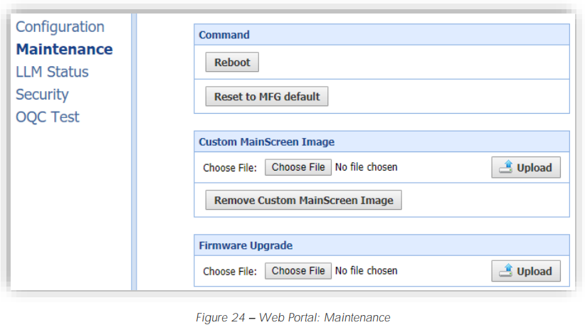
Maintenance Settings
- The Maintenance settings can be accessed by selecting the Maintenance link on the left pane.
- Soft Reboot
- To “soft reboot a unit,” select the Reboot button.
- Reset Factory Defaults
- To reset a unit’s Factory Defaults, select the Reset to MFG Defaults button.
- Change Static Image on Main Screen
- Select the Choose File button.
- Navigate to an image which is 800px X 410px.
- Select the Upload button.
- Revert Static Image on Main Screen
- Manual Firmware Upgrade
- To manually upgrade the firmware of a unit:
- Select the Choose File button.
- Navigate to a firmware file package (tar.gz file).
- Select the Upload button.
- The firmware upgrade process will take several Blink IQ 200 Level 2 AC EVSE Charging Station minutes.
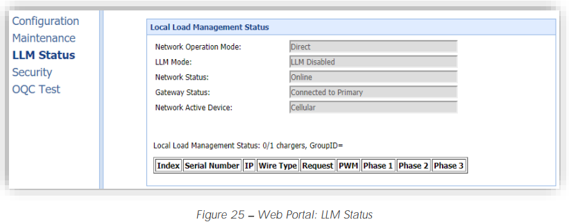
Local Load Management Status
The local load management status of a unit can be accessed by selecting the LLM Status link on the left pane.
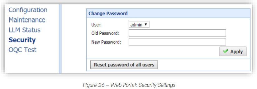
Security Settings
- The security settings of a unit can be accessed by selecting the Security link on the left pane.
OQC Test Functionality
- The OQC Test functions are reserved for testing Blink IQ 200 Level 2 AC EVSE Charging Station purposes only and must not be used for any other purpose.
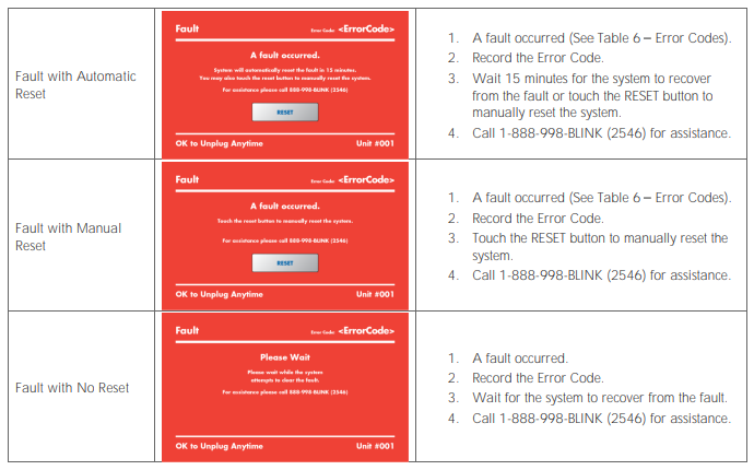
Automatic Restart Functionality
- Temporary error conditions include: Over Current, Over Voltage, Under Voltage, and Over Temperature.
- After recovery from OC condition for 30 seconds, the Blink Product will automatically restart the charge session (for 3 times).
- When a charge session stopped by the Charge Circuit Interrupting Device (CCID), the Blink Product will attempt to restart the charge session after Blink IQ 200 Level 2 AC EVSE Charging Station 15 minutes (for 3 times).
Specification
| BLINK IQ 200 PRODUCTS | |||
| POWER SPECIFICATIONS | ADVANCED CHARGING STATION | SMART CHARGING STATION | KIO SK |
| Input/ O utput Power (Max.) | 19.2k | W Max. | 19.2W Max. Input O nly |
| Input/ O utput Power (Standby) | <10W | Standby | <10W Standby |
| Input/ O utput Power | 2.9, 3.8, | 5.8, 7.7, 9.6, 15.4, 17.3, 19.2kW | 19.2W Max. Input O nly |
| Input/ O utput Amperage | Software Selectable: 12A, 16A, | 24A, 32A, 40A, 64A, 72A, 80A | 0.08A Continuous Input O nly |
| Circuit Breaker O ptions | 15A, 20A, | 30A, 40A, 50A, 80A, 90A, 100A | 15A or 20A |
| Input/ O utput Voltage | 208VAC | / 240VAC | 120/ 208/ 240VAC Input |
| Input / O utput Voltage Range | 180VAC | to 264VAC | 90 to 132VAC, 180 to 264VAC Input |
| Input / O utput Frequency | 60Hz | ||
| Input Wiring Type | Hardwired | ||
| Input Wiring Scheme | L1, L | , GND | L1, N, GND or L1, L2, GND |
| Power Measurement Accuracy | Embedded meter with a ±1% | accuracy at the nominal input. | Not Applicable |
| Surge Protection | Up to 6kV at 3,000A | ||
| Local Area Network (LAN) | 2.4GHz Wi-Fi (802.11 b/ g/ n) | ||
| Wide Area Network (WAN) | Cellular (3G GSM, 3G CDMA) | None | Cellular (3G GSM, 3G CDMA) |
| Network Interface | Blink O CPP, O CPP v1.6J | ||
| Mounting Type | Pedestal or Wall Mount | ||
| SAFETY & C | OMPLIANCE SPECIFICATIONS | ||
| Ground Fault Detection | CCID20, 20mA per UL 2231, Automati | c Reset Feature and Manual Reset Feature | Not Applicable |
| Ground Monitor | Ground Moni | tor per UL 2231 | Not Applicable |
| Safety Compliance | UL and cUL | , NEC Article 625, RoHS, Norma Oficial Mexicana | na (NO M) |
| Protection | O ver-Voltage (OVP), Under-Volta | ge (UVP), Over-Current (O CP), Over-Temperature | (O TP), and Short-Circuit Protection |
| EMC Compliance | FCC Part 15 Class B, Industry Canada (IC), PTCRB | ||
Troubleshooting
Error Codes
| Error Code | Error Name | Error Description |
| 1000 | NoError | No error to report. |
| 1001 | GroundFailure | Ground fault circuit interrupter has been activated. Same as CCID protection. |
| 1002 | MissingGroundFailure | Failure of missing ground of AC inputs. |
| 1003 | PowerSwitchFailure | Failure to control power switch. |
| 1004 | PowerMeterFailure | Failure to read power meter. |
| 1005 | ReaderFailure | Failure with ID tag reader. |
| 1006 | DisplayFailure | Failure with LCD display or touch panel. |
| 1007 | CellularModemFailure | Failure with cellular modem. |
| 1008 | WiFiModuleFailure | Failure with Wi-Fi module. |
| 1009 | ResetFailure | Unable to perform a reset. |
| 1010 | HighTemperature | Temperature inside charge point is too high. |
| 1011 | LowTemperature | Temperature inside charge point is too low |
| 1012 | OverVoltage | Voltage has increased higher than an acceptable level. |
| 1013 | UnderVoltage | Voltage has dropped below an acceptable level. |
| 1014 | ControlPilotFailure | Failure with control pilot circuit |
| 1015 | ClockFailure | Failure with internal clock. |
| 1016 | SelfTestFailure | Failure with self-tests. |
| 1017 | WeakSignal | Wireless communication device reports a weak signal. |
| 1018 | OtherError | Other type of error. |
| 2001 | LowTemperatureWarning | Low temperature warning. |
| 2002 | HighTemperatureWarning | High temperature warning. |
| 2003 | OverVoltageWarning | Over voltage warning. |
| 2004 | UnderVoltageWarning | Under votage warning. |
| 2005 | OverCurrentWarning | Over current warning. |
Reference Codes
| Error Code | Error Name | Error Description |
| 3000 | Accepted | Identifier is allowed for charging. |
| 3001 | Blocked | Identifier has been blocked. N ot allowed for charging. |
| 3002 | C oncurrentTx | Identifier is already involved in another transaction. |
| 3003 | Expired | Identifier has expired. N ot allowed for charging. |
| 3004 | Invalid | Identifier is unknown, including suspended account, invalid RFID, or inactive RFID. N ot allowed for charging. |
| 3005 | N oC redit | However, the balance of this account or credit card has exceeded |
| 3006 | C reditAuthFailed | Failed to authorize user s payment credit, especially for smart credit cards, Apple Pay, and G oogle Pay. |
LLC
The contents of this document have been verified by the manufacturer to be consistent with the described Blink IQ 200 Level 2 AC EVSE Charging Station Blink IQ 200 Level 2 AC EVSE Charging Station components; however, inconsistencies sometimes occur. Disclaimer of Consequential Damages Blink Network, LLC is not responsible for the use or application by any person of the materials in this manual. Blink Network, LLC is not responsible for damages, either direct or consequential, arising out of or relating to the use or application of these materials.
Customer Support
This document is the Property of Blink and should not be copied, reproduced, or ordered on he bbasismof oromanufacturing manufacturing apparatus without the written permission of Blink. For any support on installation and commissioning.
- Ph: 888-998-2546
- Timings: 12 hours from 9:00 AM to 1:00 AM
- Website: support@blinkcharging.com
FAQs
Which vehicles can use the Blink IQ 200 Level 2?
All EVs and plug-in hybrid electric vehicles (PHEVs) that adhere to the SAE J1772 charging standard can use the IQ 200. Always check the charging port on your car before using it.
What is Level 2 charging, and how fast does it charge?
Compared to typical Level 1 (120V) charging, Level 2 charging offers up to 9.6 kW (40A, 240V) for faster charging. Depending on your car’s internal charger, it can add 20 to 30 miles of range each hour on average.
Can I monitor charging remotely?
Indeed. You may monitor energy usage, start and stop charging, and get alerts about charging issues or status using the Blink app.
Can I schedule charging sessions to save on electricity costs?
Indeed. You may automatically lower electricity expenses by scheduling charging during off-peak hours with the Blink app.
What happens during a power outage?
The charging station will shut off on its own. Restart charging through the app or station.
Can multiple vehicles charge at once?
Every car needs a specific charging station of its own.