
Dometic TLB100 Power & Control Tempra
Safety instructions
- In the vent of a fire, use a fire extinguisher that is suitable for electrical devices
- Do not operate the device if it is visibly damaged.
- Installation, assembly, and wiring, as well as all other work, may only be performed by qualified electrical specialists. Inadequate repairs may cause serious hazards.
- Installation in potentially explosive areas such as rooms with inflammable liquids or gases is not permitted.
- Do not install or keep the device near flames or other heat sources (heating, direct sunlight, gas oven,s etc.).
- Children shall not play with the appliance.
- Check that the voltage specification on the data plate corresponds to that of the energy supply.
- Never immerse the device in water.
- Protect the device and cables against heat and moisture.
- Do not expose the device to rain.
- Ensure that the mounting surface is capable of supporting the weight of the device.
- Lay the cables so that they cannot be tripped over or damaged.
- Use ductwork or cable ducts if it is necessary to lay cables through metal panels or other panels with sharp edges.
Scope of delivery
| Description | Quantity |
| Battery | 1 |
| Red terminal protection cap | 1 |
| Black terminal protection cap | 1 |
| Operating manual | 1 |
Target group
The electrical installation and setup of the device must be performed by a qualified electrician who has demonstrated skill and knowledge related to the construction and operation of electrical equipment and installations, and who is familiar with the applicable regulations of the country in which the equipment is to be installed and/or used, and has received safety training to identify and avoid the hazards involved. All other actions are also intended for non-professional users.
Intended use
The battery is intended to provide energy to the appliances and equipment in a motorhome. The battery is intended to be used with 12 V electrical systems.
This product is only suitable for the intended purpose and application in accordance with these instructions.
This manual provides information that is necessary fothe r proper installation and/or operation of the product. Poor installation and/or improper operation or maintenance will result in unsatisfactory performance and a possible failure.
The manufacturer accepts no liability for any injury or damage to the product resulting from:
- Incorrect installation, assembly, or connection, including excess voltage
- Incorrect maintenance or use of spare parts other than the original spare parts provided by the manufacturer
- Alterations to the product without express permission from the manufacturer
- Use for purposes other than those described in this manual
Technical description
- The battery is manufactured with Lithium (LiFePO4) technology and employs high-density power (HDS) cells.
- The battery is equipped with an N-BUS communication protocol that allows all devices (equipped with the same protocol) to be connected in a single energy network. With the optional display or the mobile phone application, the connected devices can be controlled, monitored, and their firmware can be updated.
- The battery features an internal battery management system (BMS) to automatically regulate the charge input to the battery and to fully automate cell balancing.
- TLB100F, TLB120, F, and TLB150F: Heated versions of the battery are designed to withstand low temperatures, as low as – 30°C.
- The battery is equipped with a multicolor status LED.
- The battery features Bluetooth® BLE 5.0 technology for smartphone connectivity.
Installation
Installing the battery
- When working around a battery, do not allow tools to bridge the battery terminals or short-circuit any part of the battery.
- To prevent damage to the equipment, deactivate all loads and the charger before battery installation.
- Battery cables must not be connected to the battery in reverse polarity; otherwise, damage to the device may occur.
- To prevent damage to the equipment, always connect the positive cable first.
- Never connect multiple batteries in series.
- The battery may only be installed in an upright position on a horizontal surface.
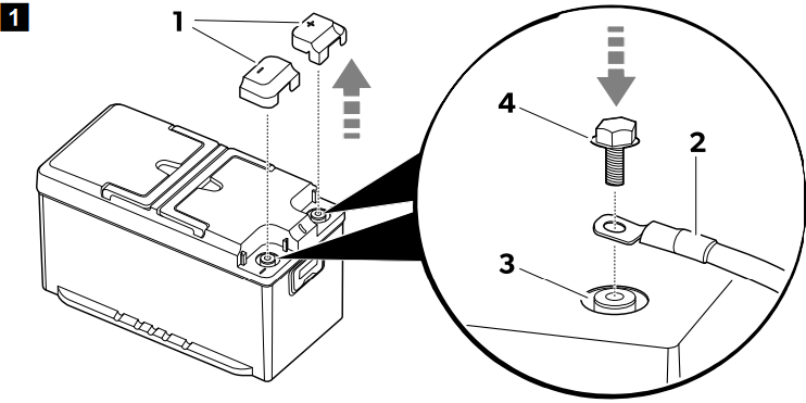
- Remove the terminal protection caps (1).
- Install the terminal protection caps (1).
- If possible, secure the battery to the floor to avoid unexpected movements during the journey.
Installing and connecting the display (optional)
- Follow the instructions given in the display manual.
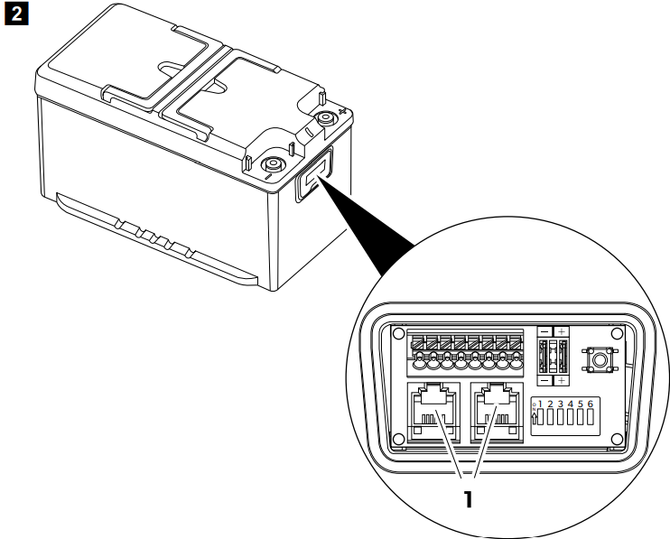
- Plug the display’s connection cable into one of the N-BUS sockets (1).
- To connect the battery with a Bluetooth® BLE compatible (v. 4.2 or higher) smartphone, download the Dometic Energy application: Download the NDS | DOMETIC app.
- Once switched on, the battery will be visible with the name ‘TLB100xxxxx’ (‘xxxxx’ representing the serial number of the battery) in the Bluetooth menu of the Dometic Energy app.

Battery configuration
Selecting the desired BUS
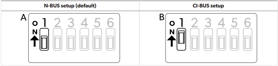
The battery supports both the native N-BUS protocol and the CI-BUS protocol that is shared with other manufacturers.
- To select the N-B, the US deactivates the DIP switch 1 (A).
- To select the CI-, BUS activate the DIP switch 1 (B).
Setting the battery as MASTER or SLAVE
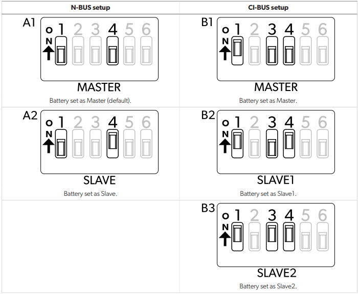
N-BUS setup
- To set this battery as Master: Deactivate DIP switch 4 (A1).
- To set this battery as Slave: Activate DIP switch 4 (A2).
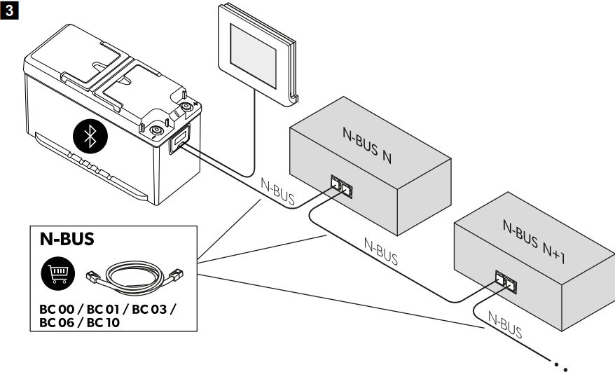
- To configure the N-BUS network, connect the N-BUS compliant devices (N, N+1, …) in series as shown.
- The cable between the battery and the display is included in the display’s scope of delivery.
CI-BUS setup
- To set this battery as Master: Deactivate the DIP switches 3 and 4 (B1).
- To set this battery as Slave1: Deactivate DIP switch 3 and activate DIP switch 4 (B2).
- To set this battery as Slave2: Activate the DIP switches 3 and 4 (B3).
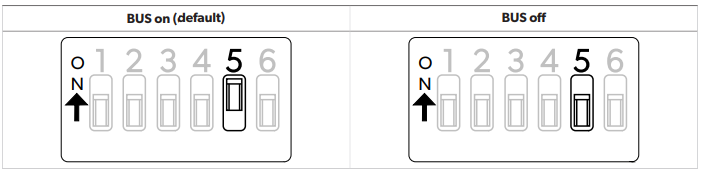
Switching the BUS power supply on or off
The selected BUS (N-BUS or CI-BUS) can be switched on or off. Switching off the selected BUS also switches off all connected devices (e.g., the display).
- To turn the BUS power supply on, activate the DIP switch 5.
- To turn the BUS power supply off,ff deactivate the DIP switch 5.
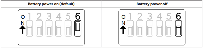
Switching the battery power supply on or off
- To turn the battery on, activate the DIP switch 6.
- To turn the battery off, deactivate the DIP switch 6.
Connecting batteries in parallel
Connect the batteries in the following order: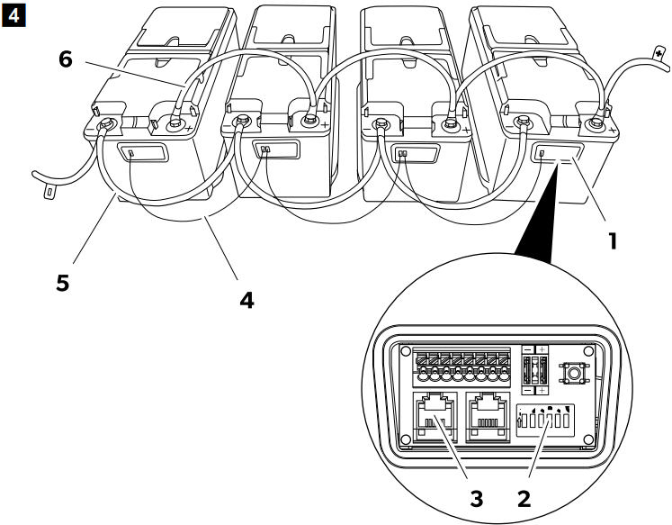
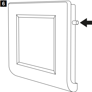
- Open the connection box (1) of the batteries.
- Select the master mode for one of the batteries by deactivating its DIP switch 4 (2).
- Select the slave mode for all other batteries by activating their DIP switches 4 (2).
- Establish the N-BUS network by connecting the batteries with cables (4) equipped with RJ12 6C/6P plugs (3). When several batteries are connected in parallel on the N-BUS network, only one must be configured as Master and the others as Slave (Selecting the desired BUS on page 10).
- Connect the negative terminals (5) of the batteries.
- Connect the positive terminals (6) of the batteries.
Wire and fuse sizing
In order to properly dimension wiring and fuses, the distances and loads must be analysed. As it is not possible to provide a unique figure valid for every application, the following examples are purely indicative.
| Estimated maximum consumption | M | maximum wire cross-section | tion | Fuse |
| Length ≤ 2 m | Length 2 m … 4 m | Length ≥ 4 m | ||
| 20 A (refrigerator, lights, water pump) | 4 mm² | 6 mm² | 10 mm² | 40 A |
| 130 A (inverter with coffee machine, and hairdryer) | 25 mm² | 35 mm² | 50 mm² | 150 A |
| 200 A (inverter with air conditioner) | 35 mm² | 50 mm² | 70 mm² | 200 A |
Operation
The factory setting for the battery is the inactive mode: No voltage is present at the terminals. To use the battery, it must be activated and switched on.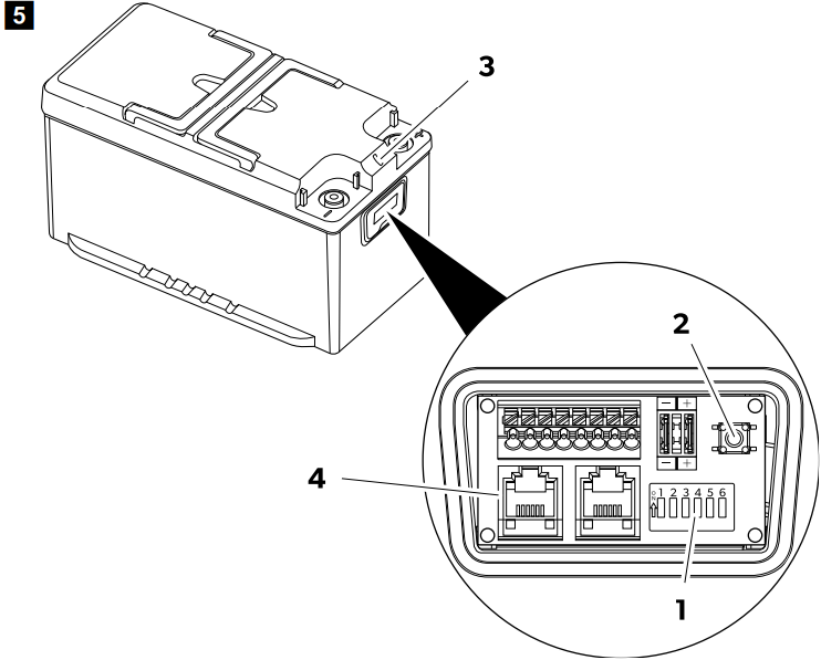
- Ensure that the DIP switch 6 (1) is set to the on position (factory setting). If other devices are connected to the battery via the BUS (4), ensure that DIP switch 5 is set to the on position (factory setting).
- Press and hold the On/Off switch (2) for 1 s. The battery is active when the LED (3) lights up.
Shutting down
- With the display button
- With the On/Off switch
- With the DIP switch 6
- With the smartphone application
- The battery will turn off with the Bluetooth® function remaining active.
- To switch off the battery together with the Dometic TLB100 Power & Control Tempra Bluetooth® function, press and hold the On/Off switch (2) for 8 s until the LED (3) starts flashing in purple.
- To switch off the battery, leaving the Bluetooth® function active, press and hold the On/Off switch (2) for 4 s until the LED (3) starts flashing in blue.
- To deactivate the battery for a longer time (e.g., for storage), push the DIP switch 6 (1) into the off position.
Shutting down the smartphone application
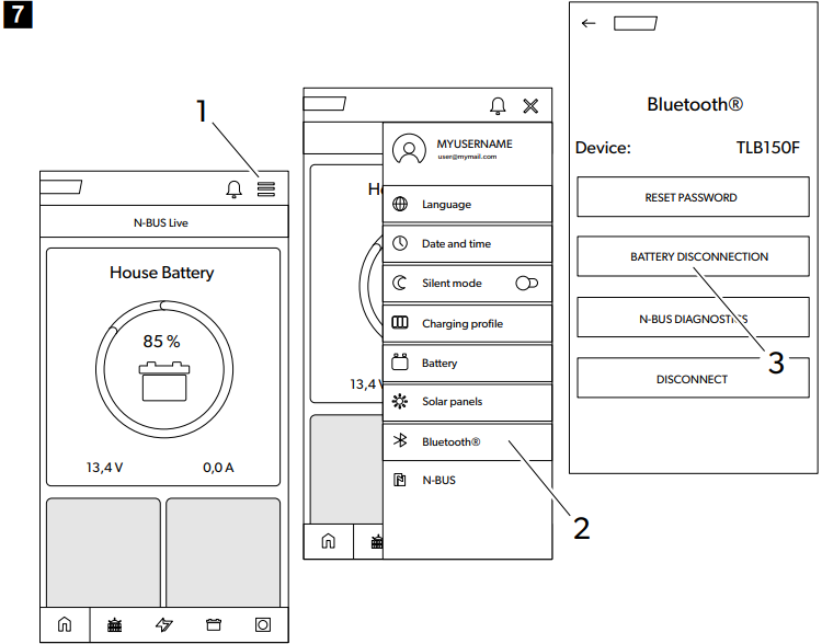
- Tap on the menu icon (1).
- Tap on the Bluetooth® icon (2).
- Tap on the battery disconnection icon (3).
The battery will switch off aer a few seconds with the Dometic TLB100 Power & Control Tempra Bluetooth® function remaining active.
LED indications
| LED indication | Description |
| Green constantly lit | Battery starting up. No voltage is present at the terminals. |
| Green flashing | Battery active. Voltage is present at the terminals. |
| Blue flashing | Battery powering down. Bluetooth® active. No voltage is present at the terminals. |
| Purple flashing | Battery powering down. Bluetooth® not active. No voltage is present at the terminals. |
| Red flashing | Battery alarm. No voltage is present at the terminals. |
| Orange flashing | Temperature range limit reached. Voltage is present at the terminals. |
| Orange constantly lit | Firmware update. |
| Off | Battery inactive. No voltage is present at the terminals. |
Charging
When charging the battery with an external charger, observe the following guidelines:
- For best results, use chargers intended for charging Dometic TLB100 Power & Control Tempra LiFePO4 batteries. If you do not have such a charger, you can use lead-acid battery chargers.
- The charger must not perform any desulfation action.
- When using a configurable charger, set the constant current/constant voltage (CC/CV) option with the following values:
- Set the end of charge voltage to 14.4 V.
- Set the recommended maximum charging current for the battery.
- The maximum charging voltage should not exceed 14.5 V. If the charging voltage is 14.7 V … 16 V, the internal battery management system (BMS) will limit the charge.
- If during charging the temperature rises above the permissible range, the internal battery management system (BMS) will limit the charge to preserve battery life.
Discharge
The internal battery management system (BMS) protects the electronic system and the battery cells. It supports a continuous current of 135 A. However, it is possible to use higher currents for a limited time, in accordance with the following values.
| Discharging current | Maximum discharging time | ||
| TLB100/TLB100F | TLB120/TLB120F | TLB150/TLB150F | |
| 150 A | 15 min | 20 min | 25 min |
| 180 A | 2 min | 3 min | 5 min |
| 200 A | 1 min | 1 min | 2.5 min |
Cleaning and Maintenance
- The batteries are maintenance-free.
- Occasionally, clean the product with a Dometic TLB100 Power & Control Tempra damp cloth
Storage
The battery is active and connected to the electrical system (e.g., of a vehicle):
- Before storing, fully charge the battery with a recommended battery charger for 1 to 2 days.
- When the battery is not in use, ensure that the battery voltage does not drop below 12.6 V.
- While storing the battery, recharge it completely every 30 days.
- Before storing, charge the battery fully or at least to 70% using a recommended charger.
- When the battery is active (green LED flashing), recharge every 6 months.
Technical data
| TLB100/TLB100F | TLB120/TLB120F | TLB150/TLB150F | ||
| Technology | LiFePO4 | |||
| Nominal voltage | 12.8 V DC | |||
| Nominal capacity, at 25°C | 100 Ah | 120 Ah | 150 Ah | |
| Nominal energy, at 25°C | 1280 Wh | 1536 Wh | 1920 Wh | |
| Number of cells in series | 4 | |||
| Recommended discharge current | 100 A | 120 A | 135 A | |
| Maximum supported discharge current | 200 A / 60s | 200 A / 150 s | ||
| End of discharge voltage | 10.5 V ± 0.1 V | |||
| Recommended charging current | 50 A / 0.5 C | 60 A / 0.5 C | 75 A / 0.5 C | |
| Maximum supported charging current | 100 A / 1 C | 120 A / 1 C | 150 A / 1 C | |
| End of charging voltage | 14.4 V ± 0.2 V | |||
| Number of cycles 80% DOD | 3500 | |||
| Operating temperature, discharge | – 20 … 60°C | |||
| Operating temperature, charge (TLB100, TLB120 and TLB150) | – 10 … 60°C | |||
| TLB100/TLB100F | TLB120/TLB120F | TLB150/TLB150F | ||
| Operating temperature, charge (TLB100F, TLB120F and TLB150F) | – 30 … 60°C | |||
| Storage temperature | – 20 … 60°C | |||
| Self-discharge | Battery deactivated: 3%/month Battery activated: 15%/month. | |||
| Maximum humidity | 95% | |||
| Pole connection size | M8 | |||
| Weight | 12.8 kg | 13.5 kg | 16.1 kg | |
| Dimensions (W x D x H) | 341 mm × 190 mm × 176 mm | |||
| Frequency band (Wi-Fi) | 2.4 GHz ISM Band (2400 … 2484) | |||
| RF Output power | 4 dBm (Bluetooth® V5.0 Single Mode LE) | |||
| Certification | 10R-06 4140 | |||
Troubleshooting
| Problem | Possible cause | Suggested remedy |
| Cell voltage high | One or more cells with a voltage above the permitted limit. | Discharge the battery by 3 Ah. |
| Cell voltage low | One or more cells with a voltage below the permitted limit. | Connect a battery charger and turn on the battery by pressing and holding the On/Off switch for 1 second. |
| Temperature problem charging | Internal battery temperature outside permissible limits. | Disconnect the charger for a few minutes. |
| Temperature problem discharging | Internal battery temperature outside permissible limits. | Avoid discharging the battery for a few minutes. |
| Short circuit | Very high current (greater than 260 A). Consumer failure. | Check that all connected consumers are working properly. |
| Overcurrent | Very high current (greater than 180 A). | Disconnect the consumer. |
| Battery overvoltage | Battery terminal voltage above 16 V. Faulty charger or wrong type of charger used. | Disconnect the charger. |
| Battery voltage low | Battery terminal voltage below 10.5 V. | The purpose of this function is to protect the battery from further discharge by keeping it switched off for a few minutes, and at the same time allowing the battery charger to detect it. |
| Battery fault | Internal failure. | Contact an authorized service agent. |
Warranty
Refer to the sections below for information about Dometic TLB100 Power & Control Tempra warranty and warranty support in the US, Canada, and all other regions.
Disposal
Place the packaging material in the appropriate recycling waste bins, wherever possible. Consult a local recycling center or specialist dealer for details about how to DOMETIC SB27150 90 Degree Bezel Kit Installation dispose of the product in accordance with the applicable disposal regulations.
Customer Service
SPAIN
- Address: Dometic Spain S.L. Avda. Sierra del Guadarrama, 16 E-28691 Villanueva de la Cañada Madrid
- Call: 8 +34 900 100 245.
- Email: info@dometic.es
GERMANY
- Address: Dometic WAECO International GmbH Hollefeldstraße 63 • D-48282 Emsdetten
- Call: 9 +49 (0) 2572 879-195
- Email: info@dometic-waeco.de
FRANCE
- Address: Dometic SAS ZA du Pré de la Dame Jeanne B.P. 5 F-60128 Plailly
- Call: +33 344633518
- Email: vehiculesdeloisirs@dometic.fr
AUSTRALIA
- Address: Dometic Australia Pty. Ltd. 1 John Duncan Court • Varsity Lakes QLD 4227
- Call: 8 +61 7 55076001|
- Email: sales@dometic-waeco.com.au
FAQs
What is the primary function of the Dometic TLB100 Tempra?
To manage and regulate heating systems, including Dometic’s Tempra water heaters or other suitable heating equipment, the TLB100 is a power and temperature control unit.
Which heating systems are compatible with the TLB100?
Its main purpose is to regulate Dometic Tempra tankless water heaters and other Dometic heating equipment that need accurate power and temperature control.
Can the TLB100 regulate water temperature automatically?
Yes, the device continuously checks and modifies the heating element to keep the water at the temperature you choose, guaranteeing a steady and secure output.
Does the TLB100 have safety features?
Indeed, it has a number of safety measures, including diagnostic alarms to guard against damage and guarantee user safety, power cut-off in the event of a malfunction, and over-temperature protection.
Is the TLB100 suitable for use in mobile applications like RVs or boats?
Of course. The unit’s small design and accurate temperature control are crucial for transportable and marine applications.
What voltage and power ratings does the TLB100 support?
In accordance with the majority of mobile power systems, the gadget normally supports a 12V or 24V DC power supply. For precise voltage and current requirements, consult your handbook.