
Hayward AQR100 Salt Chlorination System
Introduction
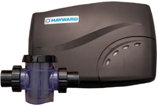
The AQR100 is an automatic chlorine generation system for pool sanitization. It automatically sanitizes your pool by converting the salt into free chlorine which kills bacteria and algae in the water. Chlorine will revert back to sodium chloride after killing bacteria. These reactions will continuously recycle virtually eliminating the need to add sanitizing chemicals to your pool. The AQR100 can handle the purification needs of most residential swimming pools up to 30,000 gallons (113,000 liters).
Safety Instructions
- To reduce the risk of injury, do not permit children to use this product unless they are closely supervised at all times.
- Do not bury the cord. Locate cord to minimize abuse from lawn mowers, hedge trimmers, and other equipment.
- To reduce the risk of electric shock, replace the damaged cord immediately.
- To reduce the risk of electric shock, install at least 10 feet (3 meters) horizontally from the inside walls of a pool or spa/hot tub. Do not use an extension cord.
- For Canadian Units: At least two lugs marked “BONDING LUGS” are provided on the external surface or on the inside of the supply terminal box or compartment.
- To reduce the risk, con- nect the local common bonding grid in the area of the hot tub or spa to these terminals with an insulated or bare copper conductor not smaller than No. 6 AWG.
Installation
Remove power to the pool filter pump before starting this installation. The Control Box must be mounted a minimum of 10 ft. horizontal distance (or more, if local codes require) from the pool and within 15 ft. from where the Cell will be installed. Take care to protect the Cell Cap connector pins while handling the AQR100 unit during installation. 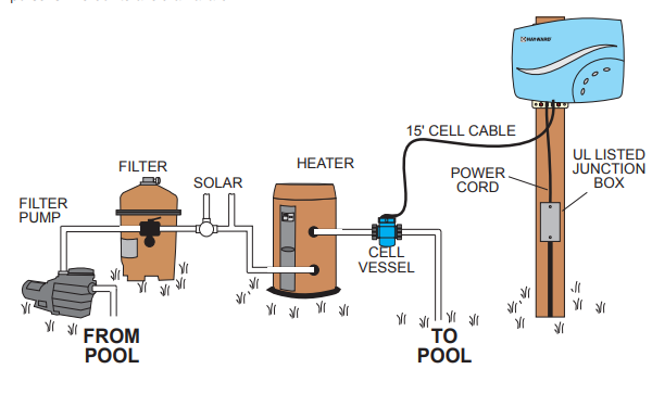
Preparing Pool Water
To prepare the pool water for AQR100 operation, the pool’s chemistry must be balanced, and salt must be added. This must be done BEFORE activating the AQR100. Some adjustments to your pool chemistry may take several hours, so start the procedure well before you intend to operate the AQR100.
To properly prepare your pool water for use with the AQR100, refer to the “Pool Chemistry” section on page 9 of this manual. Adding Salt: Add salt several hours or, if possible, 1 day before operating the AQR100. Take care not to exceed the recommended salt level. Measure salt 6-8 hours after adding to the pool.
Mounting the AQR100 Control Box
The AQR100 is contained in a rain-tight enclosure that is suitable for outdoor mounting. The Control Box must be mounted a minimum of 10 ft. (4 meters) horizontal distance (or more, if local codes require) from the pool and within 15 ft. from where the Cell is installed.
The Control Box is designed to mount vertically on a flat surface with the cables facing downward. Because the enclosure also acts as a heat sink (disperses heat from inside the box), it is important not to block the four sides of the Control Box. Do not mount the Control Box inside a panel or a tightly enclosed area.
Before securing the Control Box to the intended location, make sure that the Cell cable will reach the location where the Cell Vessel will be installed. For mounting information, refer to the diagram below. Select appropriate fasteners for your mounting surface that are suitable for a 20lb load. The mounting template shown in Step 1 can be found on page 18.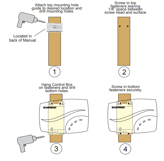
Plumbing
The Cell Vessel is designed to install in 2” (51mm) PVC pool plumbing. For pools using 1½” (38 mm) polypipe, you must use a 2” adapter. The Cell Vessel must be installed on approximately 10” run of straight pipe at the end of the return piping just before the water returns to the pool. All pool equipment should be upstream from the Cell Vessel as shown in the diagram below.
It must be located within 15 feet of where the Control Box is mounted. Also, position the Vessel in a manner where the Cell can be easily inserted and removed. With power removed to the pump and water drained from the pool plumbing, cut the plumbing in the desired location and glue the unions to the pipe. Install the included rubber gaskets on the Cell Vessel, then install the Cell Vessel into the plumbing by hand-tightening the unions.
Remove the foam protector from the Cell. Verify that the O-Ring is attached before inserting the Cell into the Cell Vessel. Fully cover the Cell pins with the supplied grease as shown.
Connect and Fasten Cell Cap
Slip the Cell Cap through the Retaining Nut as shown below. Plug the Cell Cap into the Cell and secure it with the Retaining Nut.

Wiring
Power must be shut off at the circuit breaker before performing any wiring. Be sure to follow Local and NEC electrical codes. To provide safe operation, the AQR100 should be installed by a qualified service professional and must be properly grounded and bonded.
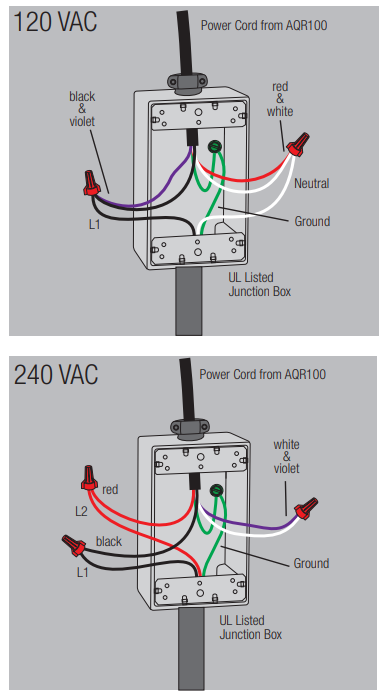
The AQR100 can be powered by either 120 VAC or 240 VAC and must be wired in a manner that the AQR100 turns on and off with the pool pump. If the pump is connected to a time clock or switch, wire the AQR100 in parallel. Locate the 6 ft. long five-conductor cable coming from the Control Box. These five colored wires are used to select voltage and apply power to the AQR100.
]Refer to the wiring label on the AQR100 as well as the diagrams on the following page to determine correct wiring connections for either 120 VAC or 240 VAC. Cut the cable and conductors to length and ensure that all connections are made within a UL-listed junction box. Attach the junction box cover when wiring is complete.
Bonding
Pool bonding or “equipotential bonding” ensures that all pool components around the pool are at the same electrical potential. If bonding is required at your location (see Local and NEC codes), bonding lugs are is provided at the bottom of the AQR100 enclosure. Run an 8 AWG solid copper wire (6 AWG Canada) from the bonding lug to your pool’s existing bonding loop.
Pool Chemistry
The table below summarizes the levels that are recommended by The Association of Pool and Spa Professionals (APSP). It is important to maintain these levels in order to prevent corrosion or scaling and to ensure maximum performance from your AQR100 chlorine generator.
Your authorized AQR100 dealer or most pool stores can provide you with the chemicals and procedures to adjust the water chemistry as well. Note that pool water emanating from wells and municipal water supplies, along with the introduction of environmental contaminants, can contain chemistries that are deleterious to the life expectancy of the Cell.
CHEMICAL IDEAL LEVELS
| Salt | 1500 to 4500 ppm (3200 ideal) |
| Free Chlorine | 1.0 to 3.0 ppm |
| pH | 7.2 to 7.8 |
| Cyanuric Acid (Stabilizer) | Outdoor Pools 30-50 ppm Indoor Pools – 0 ppm |
| Total Alkalinity | 80 to 120 ppm |
| Calcium Hardness | 200 to 400 ppm |
| Metals | 0 ppm |
| Saturation Index | -.2 to .2 (0 best) |
Saturation index
The saturation index (Si) relates to the calcium and alkalinity in the water and is an indicator of the pool water “balance”. Your water is properly balanced if the Si is 0 ± 0.2. If the Si is below -0.2, the water is corrosive, and plaster pool walls will be dissolved into the water. If the Si is above +0.2, scaling and staining will occur.
| °C | °F | Ti | Hardness Calcium | Ci | Total alkalinity | Ai | Total Dissolved Solids | TDS |
| 12 16 19 24 29 34 39 | 53 60 66 76 84 94 102 | 0.3 0.4 0.5 0.6 0.7 0.8 0.9 | 75 100 125 150 200 250 300 400 600 800 | 1.5 1.6 1.7 1.8 1.9 2.0 2.1 2.2 2.4 2.5 | 75 100 125 150 200 250 300 400 600 800 | 1.9 2.0 2.1 2.2 2.3 2.4 2.5 2.6 2.8 2.9 | 0-1000 1001-2000 2001-3000 3001-4000 4001-5000 | 12.10 12.29 12.35 12.41 12.44 |
Use: Measure the pH of the pool water, the temperature, water hardness, total alkalinity, and total dissolved solids. If the Si is equal to 0.2 or more, stains may appear. If the Si is equal to -0.2 or less, corrosion or deterioration may occur.
Salt Level
| Gallons (pool size in feet) | Liters (pool size in meters) | |
| Rectangular | Length x Width x Average Depth x 7.5 | Length x Width x Average Depth x 1000 |
| Round | Diameter x Diameter x Average Depth x 5.9 | Diameter x Diameter x Average Depth x 785 |
| Oval | Length x Width x Average Depth x 6.7 | Length x Width x Average Depth x 893 |
- For pools up to 15,000 gallons, lower salt levels (1500 – 2700 ppm) may be used. Higher levels can also be used and will require less operating time.
- For pools larger than 15,000 gallons and up to 30,0000 gallons, salt concentration should be higher than 2800 ppm.
- Note that a high salt level can begin to give a salty taste to your pool and can even cause the AQR100 to shut down. Generally, salt will begin to be tasted at a level of about 3500-4000+ ppm.
The salt in your pool is constantly recycled and the loss of salt throughout the swimming season should be small. This loss is due primarily to the addition of water because of splashing, backwashing, or draining (because of rain). Salt is not lost due to evaporation.
Type of Salt to Use
It is important to use only sodium chloride (NaCl) salt that is greater than 99% pure. This is common food quality or water softener salt and is usually available in 40-80 lb. bags labeled “Coarse Solar Salt” or “Pool Salt”. It is also acceptable to use water conditioning salt pellets, however, it will take longer for them to dissolve. Do not use rock salt, salt with yellow prussiate of soda, salt with anticakingadditives, or iodized salt.
How to Add or Remove Salt
For new plaster pools, wait 10-30 days (check with you local pool professional) before adding salt to allow the plaster to cure. Turn the circulating pump on and add salt directly into the pool
Pounds and (Kg) of Stabilizer (Cyanuric Acid) Needed for 40 Ppm
| Current Stabilizer level (ppm) | Gallons and (Liters) of Pool Water 8,000 10,000 12,000 14,000 16,000 18,000 20,000 22,000 24,000 20,000 28,000 30,000 (30000) (37500) (45000) (52500) (60000) (67500) (75000) (82500) (90000) (97500) (105000)(112500) | |||||||||||
| 0 ppm | 2.7 (1.2) | 3.4 (1.5) | 4.0 (1.8) | 4.7 (2.2) | 5.4 (2.5) | 6.0 (2.7) | 6.7 (3.0) | 7.4 (3.4) | 8.0 (3.6) | 8.7 (4.0) | 9.4 (4.3) | 10.0 (4.5) |
| 10 ppm | 2.0 (.9) | 2.5 (1.1) | 3.0 (1.4) | 3.5 (1.6) | 4.0 (1.8) | 4.5 (2.0) | 5.0 (2.3) | 5.5 (2.5) | 6.0 (2.7) | 6.5 (3.0) | 7.0 (3.2) | 7.5 (3.4) |
| 20 ppm | 1.3 (.59) | 1.7 (.77) | 2.0 (.90) | 2.3 (1.1) | 2.7 (1.3) | 3.0 (1.3) | 3.3 (1.5) | 3.7 (1.6) | 4.0 (1.8) | 4.3 (2.0) | 4.6 (2.1) | 4.9 (2.2) |
| 30 ppm | 0.7 (.31) | 0.8 (.36) | 1.0 (.45) | 1.2 (.54) | 1.4 (.64) | 1.5 (.68) | 1.7 (.77) | 1.8 (.82) | 2.0 (.91) | 2.2 (.97) | 2.4 (1.1) | 2.6 (1.2) |
| 40 ppm | 0.0 | 0.0 | 0.0 | 0.0 | 0.0 | 0.0 | 0.0 | 0.0 | 0.0 | 0.0 | 0.0 | 0.0 |
Controls
The main controls and indicators are shown below
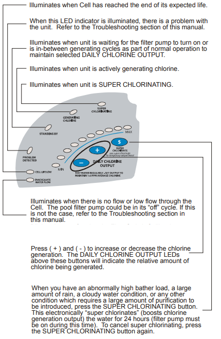
Operation
When power is first applied to the AQR100, an initialization routine will run and during this time, vari- ous LEDs will illuminate. This is perfectly normal and does not require any input from the user. When the routine is finished, the AQR100 will begin normal operation. If the water chemical levels are in the recommended range, there are three factors that you can control which directly contribute to the amount of chlorine the AQR100 will generate:
- filter time each day (hours)
- the DAILY CHLORINE OUTPUT setting
- the amount of salt in the pool
The filter pump timer/schedule should be set so that all of the water in the pool passes through the filter at least once each day. For pools with high chlorine demand, the timer may have to be set longer to generate enough chlorine.
LED Indicators
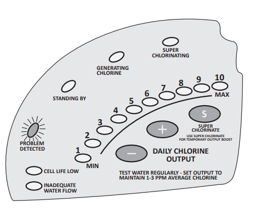
Led Possible Blinking Cause Possible Actions
| Min LED | Low Salt | 1. Check the salt level in the pool and verify that the salt level is greater than 1500 ppm but also less than 4500 ppm. |
| LED 2 | High Salt | 1. Check that the salt level in the pool is no greater than 4500 ppm and/or the temperature does not exceed 104ºF. 2. Remove power to the AQR100 for two minutes and then reapply. |
| LED 3 | Low Input Power | 1. Remove power to the AQR100 for two minutes and then reapply. 2. Verify that the AQR100 is input power wiring is correct (page 7). Make sure that there is adequate input voltage (a brownout condition could cause this error). |
| LED 4 | Temperature Sensor Error | 1. Remove power to the AQR100 for two minutes and then reapply. 2. Inspect the Cell. If dirty, follow the Cell cleaning procedure. |
| LED 5 LED 6 LED 7 LED 9 | Internal Error | 1. Remove power to the AQR100 for two minutes and then reapply. 2. Check that the salt level in the pool is no greater than 4500 ppm and/or the temperature does not exceed 104ºF. 3. Inspect the Cell Vessel and verify the cell plates are fully covered by moving water. |
| LED 8 | No Current to Cell | 1. Remove power to the AQR100 for two minutes and then reapply. |
| MAX LED | Cell Error | 1. Remove power to the AQR100 for two minutes and then reapply. |
| Inadequate Water Flow | Low Flow | 1. Remove power to the AQR100 for two minutes and then reapply. |
| Standing By | Water | 1 Remove power to the AQR100 for two minutes and then reapply. |
Daily Chlorine Output Setting
To find the optimum setting, start the Hayward AQR100 Salt Chlorination System operation with 5 DAILY CHLORINE OUTPUT LEDs illuminated. Test the chlorine level every few days and adjust up or down accordingly. It usually takes 2-3 adjustments to find the ideal setting for your pool and after that, it should only take minor, infrequent adjustments.
Because the chlorine demand of the pool increases with temperature, most people find they have to adjust up at the peak of the summer and down during colder periods. The AQR100 automatically scales back to 12 minutes of output per hour (if set higher than 12 minutes) when the pool water is 50º – 60ºF. This protects the unit as well as prevents possible over-chlorination.
The AQR100 stops generating when the pool water temperature drops below 50ºF. This is usually not a problem because bacteria and algae stop growing at this temperature. You can override these automatic low temperature operations by switching to SUPER CHLORINATE for a day.
Maintaining, Servicing and Cleaning
Mild Acid Washing: Use only in severe cases where flushing and scraping will not remove the majority of deposits. To acid wash, mix a 4:1 solution of water to muriatic acid (one gallon of water to one quart of muriatic acid) in a clean plastic container. ALWAYS Hayward AQR100 Salt Chlorination System ADD ACID TO WATER – NEVER ADD WATER TO ACID. Be sure to wear rubber gloves and appropriate eye protection.
Place the Cell in a clean container. Soak the Cell for a few minutes and then rinse with a high pressure garden hose. If any deposits are still visible, repeat soaking and rinsing. Replace Cell and inspect again periodically.
Winterizing
The AQR100 replaceable Cell will be damaged by freezing water just as your pool plumbing would. In areas of the country which experience severe or extended periods of freezing temperatures, be sure to drain all water from the pump, filter, and supply and return lines before any freezing conditions occur. The Control Box and plumbed in Cell Vessel are capable of withstanding any winter weather and should not be removed.
Spring Start-up
DO NOT turn the AQR100 on until the pool water chemistry has been brought to the proper levels. This information can be found on page 9.
Troubleshooting
Possible causes of little or no free chlorine residual
- DAILY CHLORINE OUTPUT adjustment setting is too low
- Low stabilizer (Cyanuric Acid)
- Filter pump time too short (8 hours for average size pools, more for large pools)
- Salt level too high
- Very warm pools increase chlorine demand–increase Output %, or filter run time
- Cold water below 50ºF causes AQR100 to stop generating
- Cold water between 50ºF – 60ºF causes AQR100 to reduce output regardless of DAILY
CHLORINE OUTPUT setting - Excessive scaling on Cell.
- High level of Nitrogen in pool water.
LEDs not on
- Depending on current conditions, there should always be at least one LED illuminated when the AQR100 is powered.
- If no LEDs are on, check to make sure the unit is receiving power.
- If no power is detected, the circuit breaker may have to be reset.
STANDING BY LED blinking
- The AQR100 has shut down because the temperature of the pool/spa water is too high (120ºF) or too low (50ºF). The system will not resume operation until the water temperature returns to normal.
INADEQUATE WATER FLOW LED illuminated
- The AQR100 has sensed a low flow or no flow condition and has stopped generating chlorine.
- Verify that the filter pump is running and there are no obstructions or restrictions in the pool plumbing.
- Backwash the pool filter.
- Increase the speed of your variable speed pump If the condition persists, remove the Cell from the Vessel and check that the flow switch Hayward AQR100 Salt Chlorination System is free to move in both directions. Refer to the diagram below.
Limited Warranty (effective 03/01/12)
Hayward warrants its Pro Logic, OnCommand, and E-Command pool automation products as well as its AquaRite, AquaRite Pro, Aqua Plus, and SwimPure chlorination products to be free of defects in materials and workmanship, under normal use and service, for a period of three (3) years. Hayward also warrants its Aqua Trol chlorination products to be free of defects in materials and workmanship, under normal use and service for a period of one (1) year. These warranties are applicable from the initial date of purchase on private residential swimming pools in the US and
Hayward warrants all accessories and replacement parts for the above-identified pool automation and chlorination products for a period of one (1) year. Accessories also include remotes, actuators, base stations, temperature sensors, flow switches, and chemistry probes. Each of these warranties is not transferable and applies only to the original owner.
Hayward shall not be responsible for cartage, removal, repair, or installation labor, or any other such costs incurred in obtaining warranty replacements or repair. Proof of purchase is required for warranty service. If written proof of purchase is not provided, the manufacturing date code will be the sole determinant of the date of installation of the product. To obtain warranty service or repair, please contact the place of purchase or the nearest Hayward authorized warranty service center. For more information on authorized service centers, please contact the Hayward Technical Service Support Center (61 Whitecap Road, North Kingstown, RI, 02852).
Exclusions
- Material supplied or workmanship performed by others in the process of installation.
- Damage resulting from improper installation, including installation on pools larger than the product rating.
- Problems resulting from failure to install, operate, or maintain the product(s) in accordance with the
recommendations contained in the manual (s). - Problems resulting from failure to maintain pool water chemistry in accordance with the recommendations in the manual, problems resulting from tampering, accident, abuse, negligence, unauthorized repairs or alterations, fire, flood, lightning, freezing, external water, degradation of natural stone used in or immediately adjacent to a pool or spa, war, or acts of God.
- Use of a non-genuine Hayward replacement salt chlorination cell on any Hayward automation or chlorination product will void the warranty for that product.
In no event shall Hayward Pool products be responsible for any consequential, special, or incidental damages of any nature.
Some states do not allow a limitation on how long an implied warranty lasts, or the exclusion of incidental or consequential damages, so the above limitation may not apply to you. This warranty gives you specific legal rights, and you may also have other rights, which vary from state to state.
Customer Service
- Ph: 1-800-657-2287
- Website: www.haywardcommercialpool.com
FAQs
What is the Hayward AQR100 Salt Chlorination System?
It provides constant sanitation without requiring the manual addition of chlorine by turning regular salt into chlorine.
How does the AQR100 system work?
It sanitises pool water by using electrolysis to transform dissolved salt into free chlorine.
How do I know when to add more salt?
If the salt levels are too high or too low, the device will notify you via an indicator light or digital display.
How often should I clean the salt cell?
Examine the cell every three months, and only clean it when calcium accumulation is apparent. Follow the instructions in the handbook and use a weak acid solution.
What is the lifespan of the salt cell?
The cell typically lasts three to five years, depending on system usage, water balance, and pool size.
Does this system eliminate the need for chlorine tablets?
Indeed. You won’t need to manually add chlorine or use chlorine tablets for routine sanitisation once the system is functioning correctly.