
Hayward HP21105T Heat Pump Pool & Spa
Safety Instructions
This appliance is not intended for use by persons (including children) with reduced physical, sensory, or mental capabilities, or a lack of experience or knowledge, unless they have been given supervision or instruction concerning use of the appliance by a person responsible for their safety.
- Children should be supervised to ensure that they do not play with the appliance.
- Not for use at altitudes above 2400 m.
- Maximum/ Minimum Water Temperature – 40°C(104°F) / 5°C(40°F)
- Maximum/ Minimum Water Pressure – 0.4 MPA (50 psig) / 0.03 MPA (5 psig)
- Means for disconnection must be incorporated in the fixed wiring in accordance with all applicable National and Local codes.
To Reduce the Risk of Entrapment Hazards
- When outlets are small enough to be blocked by a person, a minimum of two functioning suction outlets per pump must be installed. Suction outlets in the same plane (i.e., floor or wall) must be installed a minimum of three feet (3’) [1 meter] apart, as measured from near point to near point.
- Dual suction fittings shall be placed in such locations and distances to avoid “dual blockage” by a user.
- Dual suction fittings shall not be located on seating areas or on the footrest for such seating areas.
- The maximum system flow rate shall not exceed the f rating as listed on Table 2.
- Never use the Pool or Spa if any suction outlet component is damaged, broken, cracked, missing, or not attached.
- Replace damaged, broken, cracked, missing, or not securely attached suction outlet components immediately.
- In addition, two or more suction outlets per pump are installed in accordance with the latest ASME, APSP Standards, and CPSC guidelines, and follow all National, State, and Local codes applicable.
- Installation of a vacuum release or vent system, which relieves entrapping suction, is recommended.
- Failure to remove pressure test plugs and/or plugs used in winterization of the pool/spa from the suction outlets can result in an increased potential for suction entrapment as described above.
- Failure to keep suction outlet components clear of debris, such as leaves, dirt, hair, paper, and other material, can result in an increased potential for suction entrapment as described above.
Before You Begin
What to Expect When Operating Your Pool Heater

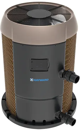
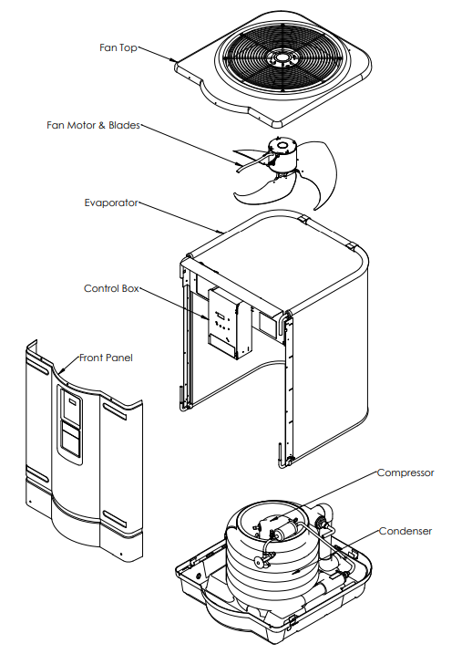
Name of Heat Pump Components
Features
- Titanium heat exchanger for harshest water conditions
- Quiet/Reliable R410A Scroll compressors
- Digital Electronic Control with
- Easy-to-read display
- Dual thermostats for independent pool and spa temperature control
- Display of diagnostic codes
- UV-resistant cabinet for long life
- Defrost function to manage evaporator coil frosting for low ambient temperature operation
- High (590PSI) and low (50PSI) refrigerant pressure switches monitor extreme operation.
- Compressor sound blanket
- Corrosion-resistanton resistant evaporator
Specification
| MODEL NUMBER HP21105T | W3HP21105T | HCB1105T | HP21205T W3HP21205T HCB1205T HP21405T | W3HP21405T | HCB1405T | HP31105T | HP31205T | HP31405T | ||||
| RATED VOLTAGE (V) | 230V~ 60Hz 1Ph | |||||||||||
| MCA (A) | 38.9 | 38.9 | 38.9 | 38.9 | 38.9 | 38.9 | 42.5 | 42.5 | 42.5 | 38.9 | 38.9 | 42.525 |
| REC. BREAKER SIZE (A) | 40 | 40 | 40 | 40 | 40 | 40 | 50 | 50 | 50 | 40 | 40 | 50 |
| MOP (A) | 65 | 65 | 65 | 65 | 65 | 65 | 70 | 70 | 70 | 65 | 65 | 70 |
| COMPRESSOR RLA (A) | 29.2 | 29.2 | 29.2 | 29.2 | 29.2 | 29.2 | 32.1 | 32.1 | 32.1 | 29.2 | 29.2 | 32.1 |
| COMPRESSOR LRA (A) | 185 | 185 | 185 | 185 | 185 | 185 | 185 | 185 | 185 | 185 | 185 | 185 |
| FAN MOTOR RLA (A) | 2.4 | 2.4 | 2.4 | 2.4 | 2.4 | 2.4 | 2.4 | 2.4 | 2.4 | 2.4 | 2.4 | 2.4 |
| FAM MOTOR HP (HP) | 1/3 | 1/3 | 1/3 | 1/3 | 1/3 | 1/3 | 1/3 | 1/3 | 1/3 | 1/3 | 1/3 | 1/3 |
| SHORT CIRCUIT CURRENT (Ka) | 5 | |||||||||||
| RMS SYMM. VOLTAGE (V) | 240 | |||||||||||
| RATED POWER INPUT (W) | 5600 | 5600 | 5600 | 6100 | 6100 | 6100 | 8300 | 8300 | 8300 | 5600 | 6100 | 8300 |
| MOISTURE RESISTANCE | IPX4 | |||||||||||
| REFRIGERANT TYPE | R-410A | |||||||||||
| REFR. SAFETY GROUP | A1 | |||||||||||
| REFRIGERANT CHARGE | 4lb 10oz | 4lb 10oz | 4lb 10oz | 4lb 14oz | 4lb 14oz | 4lb 14oz | 4lb 14oz | 4lb 14oz | 4lb 14oz | 5lb 0oz | 5lb 4oz | 5lb 4oz |
| 2.1 kg | 2.1 kg | 2.1 kg | 2.24 kg | 2.24 kg | 2.24 kg | 2.21 kg | 2.21 kg | 2.21 kg | 2.27 kg | 2.27 kg | 2.27 kg | |
| MAX ALLOWABLE REFR PRESSURE | 575 PSIG | |||||||||||
| 3.96 MPa | ||||||||||||
| HIGH SIDE | 340 PSIG | |||||||||||
| 2.34 MPa | ||||||||||||
| LOW SIDE | 236 PSIG | |||||||||||
| 1.63 MPa | ||||||||||||
| MIN WATER FLOW | 30 GPM | |||||||||||
240 VAC / 60 Hz Single Phase Wiring Diagram

Installation
Read through instructions thoroughly before installation. Installation instructions are intended for use by a qualified technician, specifically trained and experienced in the installation of this type of equipment. Some states or provinces require that the installer be licensed. If this is the case in the state or province where the heater is located, the contractor must be properly certified. Sprinkler Heads: Be sure that there are no sprinkler heads near the heater that will spray on or into the unit. Many sprinkler systems are connected to a well system whose water is high in minerals, sulfur, salt, and other aggressive contaminants that can cause corrosion and shorten life.
The Use Of A Pool Cover Is Recommended. A pool cover reduces heat loss, conserves chemicals, lowers the load on filter systems, and may provide a valuable safety feature. Materials Needed For Installation
The following plumbing items are needed.2-inch Isolation Valves qty (3)
- 2-inch Check Valve qty (1)
- 2 x 2 x 2 PVC Tees qty (2)
For proper installation, appropriate electrical supplies will be needed along with extra hardware items that may be required for anchoring.
Locating The Heater
The installation location of the heat pump is very important for its efficient operation. The heat pump will perform more efficiently when placed in direct sunlight with ample air intake and the avoidance of air recirculation. Locate the pool heater in an area where its condensation will not result in damage to the area adjacent to the heater or a nearby structure.
Outdoor Installation And Service Clearances
The heater must be installed outdoors such that the installation and service clearances shown in Table 3 and Figure 6 are maintained. Additional installation requirements are as listed:
- Suitable electrical supply line. See the rating plate on the heat pump units for electrical specifications. A junction box is not needed at the heat pump; connections are made inside the heat pump’s electrical compartment. Minimum wire size to be selected per NEC based on unit MCA.
- An electric disconnect switch that will interrupt all power to the unit. This switch MUST be within line of sight of the heat pump.
- Do not install in a location where growing shrubs may, in time, obstruct a heater’s air flow areas (sides or top).
- Do not install this appliance under an overhang less than 72in from the top of the appliance. The area under the overhang must be open on (3) sides.
- Do not install the heater where water spray from ground level can contact the heater. The water could damage the coil or reach the controls, causing electrical damage.
- Do not install under a deck.
- Do not install within 12″ of any outdoor HVAC equipment.
- Do not install where water may run off a roof into the heater. A gutter may be needed to protect the heater.
| TABLE 3: Installation Required Clearances | |
| Heater Panel | Outdoor Clearance |
| Top | Unobstructed |
| Front (control) | 24 – 36″ |
| Rest of Perimeter* | 12″ |
Outdoor Minimum Clearances

Equipment Pad: Place the heat pump on a level surface such as concrete or a fabricated slab (pad). This allows proper drainage of condensation and rainwater from the base of the unit. If possible, the pad should be placed at the same level or slightly higher than the filter system equipment pad.
Flooring: This heater may be installed on either non-combustible flooring or combustible flooring that does not reduce the bottom clearance of the heater. Ultralite™ or equivalent concrete-over-foam HVAC pads are acceptable.
Drainage and Condensation: Condensation will be produced by the evaporator coil when the unit is running and draining at a steady rate, usually three to five gallons per hour, depending upon ambient air temperature and humidity. The more humid the conditions, the more condensation will be produced.
Anchoring: The heater is equipped for the installation of anchoring screws when required by local codes. Follow all relevant Local, State, and National requirements regarding wind load anchoring. When anchoring is required to secure the heat pump to a concrete pad, use the specified hardware shown in Figure 7. To complete the installation, use the following:
- Anchor Clamps (Included)
- Concrete tapping screws (Not Included)
- Fender washers (Not Included)
- qty (8), spaced at least 2½” apart
- qty (8), Tapcons® stainless steel, size to be ¼” diameter with a minimum length of 1½”
- qty (8), stainless steel, size to be 1½”
Equipment Pad and Anchoring

Water Piping
General: The heater is for use with pool and spa/hot tub water furnished by municipal water distribution systems only. Do not use the heater for mineral water, seawater (PPM>5000), or other non-potable waters. These heat pumps are designed for nominal water flows through the condenser. A minimum flow of 30 gpm is required to ensure sufficient heat removal from the condenser, thus avoiding overheating the unit. The minimum flow rate is to be calculated or measured with the in-floor cleaning system in use, if the pool is so equipped, as well as any other jets or other demands on the water flow.
Flow rates above 75 gpm will create excessive pressure drop through the condenser and require unnecessarily high pumping energy. Bypass valve setting may be accomplished by temporarily installing a flow meter on the outlet line of the heater.
Then adjust the manual bypass valve until the flow rate through the heater is within the flow rate range specified. Once the manual bypass valve is set, note the position and remove the valve handle to prevent accidental adjustment. Failure to install an External Bypass Assembly with a flow rate of 75 GPM can cause damage. Do not install any restriction in the water pipe between the heater outlet and the po,ol except for: a three-way switching valve, an in-line chlorinator, and/or a chlorinator.
General Pad Plumbing Layout

- Improperly adjusted manual bypass valves will result in damage to the heater if the flow rates are not maintained under all operating conditions as specified in the listed SPECIFICATION.
- The heat pump must be protected from back siphoning of water. If there is any chance of back siphoning, provide a check valve between the pool and the filter pump inlet. Failure to follow the instructions may result in property damage due to flooding.

Above Pool Installation

Typical Pool Arrangement
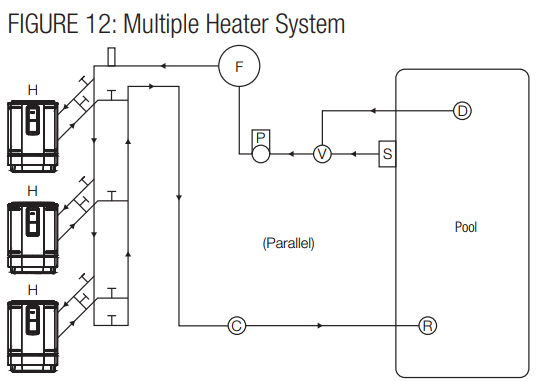
Also shown is the implementation of an optional gas or solar heater system for additional capacity. Other pool heaters, such as gas or solar-powered devices, can only be installed in a parallel circuit and operated independently (only one at a time) for your warranty to be valid. Multiple Heater System
- Maintain 12″ [31 cm] clearance between the units, 12 in. [31 cm] around the perimeter, and at least 6 ft [1,8 m] over them. Refer to the Locating the Heater section for more details.
- Install bypass loops for each unit.
- Install union style fittings from the heat pump CONSUMER KIT adjacent to the unit to facilitate easy service p.. procedures
Automatic Chlorinators and Chemical Feeders
Install a separate positive seal corrosion-resistant check valve between the heater outlet and the chlorinator to prevent highly concentrated sanitizer from back siphoning into the heater.
Electrical Wiring
The heater must also have independent ground and bond connections. There is a ground lug inside the control box adjacent to the power connections and a bonding lug on the side of the heater. Use a solid copper conductor, size 8 or larger. Run a continuous wire from the external bonding lug to the reinforcing rod or mesh. Connect a No. 8 AWG (8.4 mm2 ) solid copper bonding wire to the grounding lug provided on the heat pump and to all metal parts of the swimming pool or spa, and to all electrical equipment, metal piping (except gas piping), and conduit within 5 ft. (1.5 m) of inside walls of the swimming pool or spa. IMPORTANT – Reference NEC codes for all wiring standards, including, but not limited to, grounding, bonding, and other general wiring procedures.
Electrical Connections
Turn off the source power to the heat pump before working on electrical connections. Plug any unused openings with the supplied caps.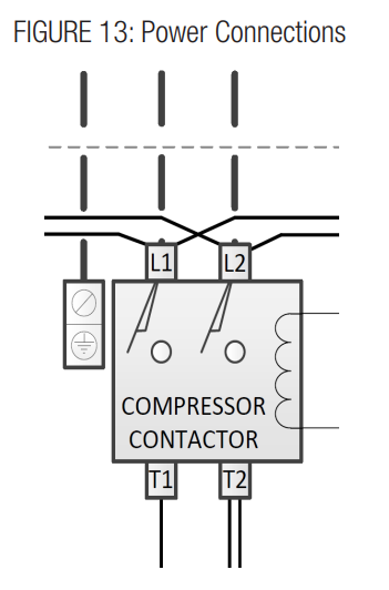
Remote Control Connection
The heater is equipped for remote control via independent 2-wire connections. Heat-only models connect the remote relay to terminal J7. Heat/Cool models connect the heating remote relay to terminal J7 and the cooling remote relay to terminal J28. (See Figure 14 for remote on/off connections).
- Connect the Heating remote relay to the J7 connection and the Cooling remote relay to the J28 connection L(if applicable) on the control board.
- Turn the unit on. Press and hold both the “MENU” and the “+” buttons until “bo” appears. This enables the bypass operation.
- In the bypass operation, when the relays are open, the heater will be off. When the heating relay (J7) is closed, the heater will operate in heating.
- The heater will shut off when both relays are open or the inlet temperature exceeds 104°F.
- If both relays are closed, the heater will operate in heating mode.

Operation
After completing the installation of connections to the pool heater, follow the procedures outlined below to ensure that the pool heater is functioning properly. Before proceeding, MAKE CERTAIN there are no water leaks in any plumbing connections or piping, and water flow is within the proper flow rate ranges.
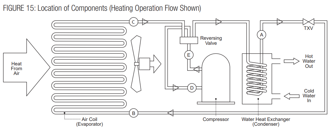
The heat pump takes heat from the environment and uses it to heat the pool water. The two-phase Refrigerant flows through the Air Coil (Evaporator), where the liquid refrigerant evaporates into vapor by absorbing heat from the surrounding air.
Heat Pump Protection Features
These heat pumps are equipped with safeguards that will stop heater operation to protect the unit in case of the following events:
- Excessively high refrigerant pressure
- Excessively high water temperature
- Loss of refrigerant
- Fan Motor Failure
- Evaporator Freeze-up
- Low Ambient Temperature
Control Setup Heat Only Models
The heater will then function automatically to maintain the desired temperature. The heater has 3 modes of operation:
- SPA -In this mode, the heater will automatically function to maintain the water temperature setting for SPA mode.
- POOL – In this mode, the heater will automatically function to maintain the water temperature setting for POOL mode.
- REMOTE OPERATION – In this mode, the heater will respond to a remote call for heat or to control unit operation mode. Use the set button in Figure 16a to select POOL/SPA modes. The arrows will indicate which mode is currently active.
Control Setup Heat/Cool Models
The heater will then function automatically to maintain the desired temperature. The heater has 4 modes of operation:
- HEAT – In this mode, the heater will automatically function to maintain the water temperature setting for HEAT mode.
- COOL -In this mode, the heater will automatically function to maintain the water temperature setting for the COOL mode
- AUTO – In this mode, the heater will automatically function to maintain the water temperature setting for AUTO. It will operate in HEAT or COOL mode as required.
- REMOTE OPERATION – In this mode, the heater will respond to a remote call for HEAT or COOL mode. Use the set button in Figure 16b to select HEAT/ COOL/AUTO modes. The arrows will indicate which mode is currently active.

Heat Only Function Selection
Push the “MENU” button to display the current selection: “On/OFF”, “POL”, “SPA”, or “F_C” will appear. When in “On/OFF” mode, push the “-” button to turn the unit off and the “+” button to turn the unit on.
Push the “MENU” button (x2) until “POL” is displayed. Then use the “-” and “+” buttons to set the Pool temperature set point as shown in the display. Setting the temperature will place the heater in POOL mode.
Push the “MENU” button (x3) until “SPA” is displayed. Then use the “-” and “+” buttons to set the Spa temperature set point as shown in the display. Setting the temperature will place the heater in SPA mode.
Push the “SET” button (x4) until “F_C” is displayed. Then use the “-” and “+” buttons to select °F or °C display as shown.
Heat Only Operation
Temperature Adjustment
This control allows the user to have 2 individual preset temperature settings, “SPA” and “Pool”. To adjust the temperature while in SPA or POOL mode, use the (Plus) and (Minus) buttons. When the numeric display adjustment is complete, the control will return to displaying the actual measured water temperature. The temperature settings for both SPA and POOL modes are initially set at the factory to 65°F. The minimum allowed settings for SPA and POOL modes are 50°F. The maximum allowed settings for heating modes iare104°F.
Dual Pool And Spa Set Points
The unit can keep two temperature settings in memory: one for pool mode (max: 95°F/35°C), and the other for spa mode (max: 104°F/40°C). The arrows on the right side of the display indicate the chosen heating mode.
Fahrenheit Versus Celsius
The control will display temperatures in either degrees Fahrenheit or Celsius. To change the temperature display, press the MENU key until you see F_C, and by pressing one of the arrow keys, you can switch to °F or °C.
Normal Operation For Pool & Spa Modes
- Apply power to the pool heater by plugging in the non-fused disconnect block or moving the circuit breaker to the “ON” position.
- Push the “MENU” button (x1) until “On/OFF” is displayed. Then use pluthe s button to select “On” mode as shown in the display. The minus button will select the
“OFF” mode. - Push the “MENU” button (x2) until “POL” is displayed. Then use the plus and minus buttons to set the Pool temperature set point as shown in the display.
- Push the “MENU” button (x3) until “SPA” is displayed. Then use the up and down buttons to set the PA temperature set point as shown in the display.
- Push the “MENU” button (x4) until “F_C” is displayed. Then use the plus and minus buttons to select Fahrenheit or Celsius mode as shown in the display.
- When the unit starts, confirm that air is being discharged upward from the unit and that he air is cooler than the ambient air.
- If the pump fails to start:
- Check temperature settings to confirm tll for heating
- Check the water flow and the water flow switch
- Ensure that the power is on
- Check the TRO the UBLE SHOOTING SECTION in the manual, or call for service.

Heat/Cool Function Selection
Push the “MENU” button to display the current selection: “On/OFF”, “HE”, “COL”, “AUT”, or “F_C” will appear. When in “On/OFF” mode, push the “-” button to turn the unit off and the “+” button to turn the unit on.
Use the “-” and “+” buttons to set the Heat Temperature Set Point as shown in the display. Selecting the set point will activate eating mode. Max. Temp. is 104°F.
Push the “MENU” button (x3) until “COL” is displayed. Use the “-” and “+” buttons to set the Cool Temperature Set Point as shown in the display. Selecting the set point will activate cooling mode. Min. Temp. is 55°F.
Use the “-” and “+” buttons to set Authe to Temperature Set Point as shown in the display. Selecting the set point will activate auto mode. Max. Temp. is 104°F.Push the “MENU” button (x5) until “F_C” is displayed. Use the “-” and “+” buttons to select °F or °C display as shown.
Heat/Cool Operation
Temperature Adjustment
This control allows the user to have 3 individual pre-set temperature settings: Heating (“HE”), Cooling (“COL”) a,, nd Automatic (“AUT”). To adjust the temperature while in Heating, Cooling, or Automatic mode, use the (Plus) and (Minus) buttons.
Fahrenheit Versus Celsius
The control will display temperatures in either degrees Fahrenheit or Celsius. To change the temperature display, press the MENU key until you see F_, and by pressing one of the arrow keys, you can switch to °F or °C.
The Defrost function is provided to prevent the evaporator coil from freezing when the outside air temperature is near 50°F (10°C). The temperature at which this function will operate is not exact, t, and each unit will vary depending upon conditions surrounding the heat pump, clearance around the heat m p, and heat pump maintenance. This time period will vary depending on ambient air conditions.
Operation For Heat, Cool & Auto Modes
The control continually compares the water temperature with the set point and the high limit temperature.
- Then just use the plus button to select “On” mode as shown in the display. The minus button will select the “OFF” mode.
- When using the plus and minus buttons to set the heating temperature set point, as shown in the display.
- Then use the plus and minus buttons to set the Cooling temperature set point as shown in the display.
- Then use the plus and minus buttons to select Fahrenheit or Celsius mode as shown in the display.
- The fan will start immediately. Allow 3 minutes for the Heat Pump to start.
- Allow the Heat Pump to operate for 10-15 minutes in order for the system pressure to stabilize.
- If the Heat Pump fails to start:
- Check temperature settings to confirm call for heating/cooling.
- The heck water flow and water heater flow switch
- Ensure that the power is on
- Check the TROUBLE SHOOTING SECTION in this manual or call for service
Water Testing
- Be sure the filter is clean before making any adjustment.
- Turn “ON” the filter pump and ensure all air is out of the water lines, and ensure the water flow rate is at
least the rated minimum. - Turn “ON” the heater and adjust the temperature control to create a call for heat.
- Check the function of the pressure switch by turning the filter pump on and off several times. Never allow the heater to operate with less than the minimum rated water flow rate.
Maintenance & Service
- Periodically check the fan discharge area. Remember Hayward HP21105T Heat Pump Pool & Spa that shrubs grow and, in time, may obstruct
- Keep the entire pool heater area clean and free of all debris, corrosive materials, and other flammable vapors and liquids. Remove any leaves or paper from around the heater.
- Do not store chlorine, other pool chemicals, or other corrosives in the vicinity of the heater.
- Do not use the heater if any part has been underwater. Contact a qualified service technician to inspect the entire heater and replace any part of the control system that was underwater.
- An inspection program is a good preventative maintenance measure. Keep this manual in a safe place for future reference for yourself as well as for a service technician to consult when inspecting or servicing the heater.
Water Chemistry
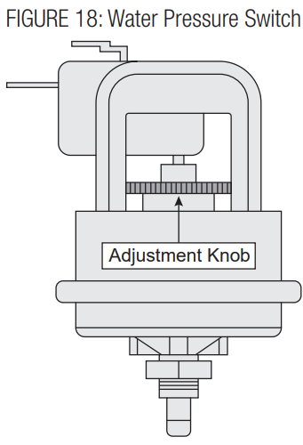
Some installations may require an adjustment to the water pressure switch for proper low-flow protection.
Water Chemistry
The chemistry balance and mineral content of swimming pools and spas change rapidly due to the addition of sanitizing chemicals, user exposure to the air, the effect of sunlight, and more. Improper chemistry balance and mineral content can cause scaling and deposits to form on pool walls, in the filtration system, in the heat exchanger t,, and additionally can promote corrosive action to all metals in the water path.
| Chemical | Recommended Level | Effect of Low Levels | Effect of High Levels |
| Chlorine | 1 – 3 ppm | Hazy water, algae growth wth bacteria causing infections | Swimmer irritation, bleaching of clothes/hair, corrosive to the heat exchanger |
| Bromine | 2 – 4 ppm | ||
| pH | 7.4 – 7.6 | Corrosion of the heat exchanger, swimmer irritation | Cloudy water, scaling of the heat exchanger, red and uced sanitizer effectiveness |
| Total Alkalinity | 80 – 120 ppm | Corrosion of the heat exchanger, large fluctuations in pH | Scaling of the heat exchanger |
| Calcium Hardness | 200 – 400 ppm | Corrosion of the heat exchanger | Scaling of the heat exchanger |
| Salt | 2700 – 5000 ppm | Poor salt chlorinator performance | Corrosion of the heat exchanger |
Skimmer Chlorination
Placing chlorine or bromine Tablets directly into the Hayward HP21105T Heat Pump Pool & Spa skimmer may result in high chemical concentrations flowing through the heater. DO NOT place chlorine or bromine Tablets in the skimmer.
Winterization
In moderate climates, the heater can continue to operate during short-term cold spells. Do not use the heater to maintain the water temperature just above freezing or for freeze protection.
- Set the heater to STANDBY mode using the keypad.
- Turn the electricity to the heater OFF at the circuit breaker panel.
- Be sure the circulating pump is OFF.
- If no drain plug is provided, open the lower inlet water union and allow all water to drain from the heater.
- Reinstall the drain plug or reattach the water union.
Spring Start-Up
- Inspect and clean the heater, being sure the heater is free of leaves and debris prior to startup.
- Properly attach the inlet and outlet piping and confirm the drain valve is closed.
- Turn the filtration system pump ON and Hayward HP21105T Heat Pump Pool & Spa allow the system to run long enough to purge all the air from the lines.
- Turn the electricity to the heater ON at the circuit breaker panel.
- Set the temperature control using the keypad to an operating mode (“POOL”, “SPA”, “HEAT”, “ COOL”, or “AUTO”) and adjust the set point to the desired temperature setting.
- If operating difficulties are encountered, contact a qualified service company for assistance.
Component Service
Control System: The control system in this heater consists of the display keypad/control board and the terminal board. The locations of these components are shown in Figure 5. The control board functions as the heater’s thermostat operator and safety controls. Stemm, to remove/replace the display keypad/control board:
- Turn the pump and heater power OFF.
- Remove the front access panel.
- Disconnect all wires from the printed circuit board.
- Detach the board from the access panel by removing the mounting screws.
- Replace the board, and reverse the above steps to reassemble.
Thermistor: The thermistor monitors the return water temperature to thermostatically control pool and spa water to the selected temperature., Shut the heater off if the return water reaches 104104°F.o To replace the thermistor:
- Turn pmp, and heater power “OFF”.
- Remove the front access panel.
- Unplug the thermistor connector from the terminal board.
- Undo the wire connection in the control box Hayward HP21105T Heat Pump Pool & Spa and push the leads through the hole in the control box.
- Withdraw the thermistor from the well in the water header.
- Replace the thermistor.
- Revise the steps above to complete the procedure.
Water Pressure Switch / Flow Switch
When the heater is located above or below the Hayward HP21105T Heat Pump Pool & Spa level of the pool or spa, the pressure switch may require adjustment to compensate for the change in static head pressure. Flow switches are not adjustable. Please verify that there is adequate water flow to meet minimum water flow requirements (see Specifications section)
To replace the pressure switch:
- Turn ump, and heater power “OFF”.
- Remove the hose from the switch body external to the control box.
- Remove the wires from the pressure switch.
- Replace the pressure switch.
- Revise the steps above to complete the procedure.
To replace the flow switch
- Turnpump, and heater power “OFF”.
- Remove the flow switch wires from the control board.
- Replace the flow switch.
- Revise the steps above to complete the procedure.
Transformer: The transformer converts the field Hayward HP21105T Heat Pump Pool & Spa supply voltage to 24 VAC output for powering the control board. To replace the transformer:
- Turnpump, and heater power “OFF”.
- The front access panel.
- Disconnect all wires from the transformer leads.
- Remove the (2) screws that secure the Hayward HP21105T Heat Pump Pool & Spa transformer to the control box.
- Replace the transformer. Reassembly is the reversathe the lthe of the steps above.
Contactor: The switches the incoming power to the compressor. To replace the contactor:
- Turnpump, and heater power “OFF”.
- Remove the front access panel.
- Disconnect all wires from the contactor terminals keep track of wire locations.
- Remove the (2) screws that secure the contactor to the control box.
- Replace the contactor. Reassembly is the reversal of the steps above.
Troubleshooting
| TABLE 5: Display Code Index | |||
| Display | Problem | Possible Cause | Information |
| (blank) | No powethe the r to the heat pump | Tripped circuit breaker, no power supply | The breaker ensures that the unit is properly installed. |
| Faulty electrical component | Call thethethee unit | ||
| nit will not turn on | M.aster power switch off | Turn the master power switch on. | |
| Unit on 5-minute delay | Wait 5 minutes. | ||
| FLo | Water Pressure Switch / Flow Switch circuit open | Low or no water flow | Normal operation for remote on/off. |
| Eck w er through the water pump. Ensure the pool pump is on. | |||
| Clean your filter. | |||
| Make sure all valves are fully open and the bypass valve is closed. | |||
| Turn off fountains, Low-pressure switch | |||
| witch circis uit open | Air flow obstruction | Remove debris, etc., restricting air flothe the w to the heat exchanger. | |
| Low ambient temperature cutoff | Wait for the outside temperature to reach 60°The unit | ||
| It’s low on refrigerant | Call for service. | ||
| High-pressure | switchwitch circuit open | Low water flow | Chethe the ck water flothe w to heat pump. Ensure the pool pump is on. |
| Clean your filter. | |||
| Make sure all valves are fully open and the bypass valve is closed. | |||
| Turn off fountains, etc. | |||
| High water temp | Check pool temperature. Wait til the pool needs heat. | ||
| Call for service. | |||
| SO | Water Temperature sensor open | Sensor not connected to the control board | Call for service. |
| SS | Water Temperature sensor short circuit | Sensor or sensor wires are shorted | Call for service. |
| FS | Defrost Mode | Frost buildup on the evaporator coil | No action required. The unit is defrosting automatically. |
| dSO | Coil Temperature sensor open | Sensor not connected to the control board | Call for service. |
| dSS | Coil Sensor short circuit | Sensor or sensor wire res shortened | Call for service. |
Service Parts List
The following repair parts are available from Hayward and through your local distributor. When ordering parts, include the complete pool heater model number listed on the unit’s rating plate, located near the junction boxes on the exhaust side of the heater.
Refrigeration Parts
- Compressor
- Thermal Expansion Valve (TXV)
- Evaporator
- Condenser
- Filter Drier
- Reversing Valve
- Compensator
Electrical Parts
- Fan Motor
- Control Board
- Capacitor, Compressor
- Capacitor, Fan
- Contactor
- Fan Relay
- Transformer
- HP Switch
- LP Switch
- Defrost Sensor
- Water Temperature Sensor
- Water Flow Switch
- Water Pressure Switch
- Plug, Compressor
- Instrument Elbow Assembly
Miscellaneous Parts
- Evaporator Guard
- Fan Blade
- Fan Guard
- Panel-Top Kit, Black
- Panel-Top Kit, Taupe
- Gasket-35 In, Neoprene (Qty 2)
- Bracket, Bottom (Qty 4)
- Fastener, Tree, 1/4 (Qty 25)
- Fastener, U-Type (Qty 25)
- Consumer Kit
Limited Warranty (effective 03/01/12)
Hayward warrants its Pro Logic, OnCommand, and E-Command pool Hayward HP21105T Heat Pump Pool & Spa automation products as well as its AquaRite, AquaRite Pro, Aqua Plus, and SwimPure chlorination products to be free of defects in materials and workmanship, under normal use and service, for a period of three (3) years. Hayward also warrants its Aqua Trol chlorination products to be free of defects in materials and workmanship, under normal use and service for a period of one (1) year. These warranties are applicable from the initial date of purchase on private residential swimming pools in the US and
Canada. Hayward warrants all accessories and replacement parts for the above-identified pool automation and chlorination products for a period of one (1) year. Accessories also include remotes, actuators, base stations, temperature sensors, flow switches, and chemistry probes. Each of these warranties is not transferable and applies only to the original owner.
Hayward shall not be responsible for cartage, removal, repair, installation labor, or any other such costs incurred in obtaining warranty replacements or repairs. Written proof of purchase is not provided; the manufacturing date code will be the sole determinant of the date of installation of the product. To obtain warranty service or repair, please contact the place of purchase or the nearest Hayward authorized warranty service center. For more information on authorized service centers, please contact the Hayward Technical Service Support Center (61 Whitecap Road, North Kingstown, RI, 02852).
Exclusions
- Material supplied or workmanship performed by others in the process of installation.
- Damage resulting from improper installation, including installation on pools larger than the product rating.
- Problems resulting from failure to install, Hayward HP21105T Heat Pump Pool & Spa operate, or maintain the product(s) in accordance with the
recommendations contained in the manual (s). - Problems resulting from failure to maintain pool water chemistry in accordance with the recommendations in the manual, Hayward HP21105T Heat Pump Pool & Spa problems resulting from tampering, accident, abuse, negligence, unauthorized repairs or alterations, fire, flood, lightning, freezing, external water, degradation of natural stone used in or immediately adjacent to a pool or spa, war, or acts of God.
- Use of a non-genuine Hayward replacement salt chlorination cell on any Hayward automation or chlorination product will void the warranty for that product.
In no event shall Hayward Pool products be responsible for any consequential, special, or incidental damages of any nature. Some states do not allow a limitation on how long an implied warranty lasts, or the exclusion of incidental or consequential damages, so the above limitation may not apply to you. This warranty gives you specific legal rights, and you may also have other rights, which vary from state to state.
Customer Service
- Ph: 1-800-657-2287
- Website: www.haywardcommercialpool.com
FAQs
What is the Hayward HP21105T Heat Pump used for?
By drawing heat from the surrounding air and transferring it to the water, the HP21105T energy-efficient heat pump prolongs the swimming season in pools and spas.
What pool size is this heat pump suitable for?
For pools up to 25,000–30,000 gallons, this unit’s 110,000 BTU rating is usually appropriate, depending on the climate, the desired water temperature, and the pool’s usage.
What type of electrical supply is required for installation?
This item needs to be hardwired by a licensed electrician in accordance with local electrical rules, and it needs a 240V dedicated circuit with adequate amperage protection (typically 50A).
Can I install the heat pump myself?
Expert installation is highly advised. Inadequate plumbing or electrical installation might result in performance problems, warranty voiding, or safety hazards.
Where should the heat pump be installed?
Only place the device outside on a level, sturdy, non-flammable surface (such as a concrete pad). For adequate ventilation, leave at least 60 inches above and 24 to 36 inches around the sides.
What is the ideal water flow rate for this unit?
Between 30 and 75 GPM (gallons per minute) is the suggested flow rate. Make sure the piping system and pump can sustain this range.