
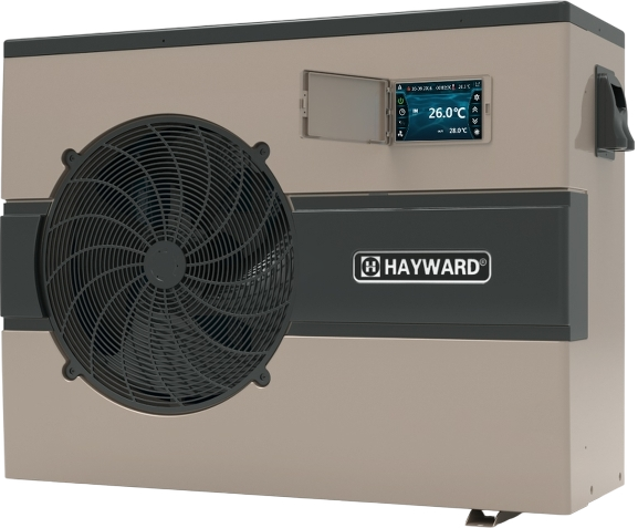
Hayward R32 Swimming Pool Heat Pump Unit
Safety instructions
This device contains R32. Never use a refrigerant other than R32. Any other gaseous body mixed with R32 could cause abnormally high pressure and lead to a failure or pipes bursting and injuring people. When carrying out repairs or maintenance work, never use copper tubes less than 0.8 mm thick. There is a risk of explosion. Never expose the device to flames, sparks, or other sources of ignition. It could explode and cause serious or even fatal injuries.
- (M/(2.5 x 0.22759 x h0))². M is the quantity of refrigerant in the device in kg, and h0 is the storage height. If stored on the floor, h0 = 0.6 m.
- Do not install the heat pump on a support that risks intensifying the unit’s vibrations.
- Make sure the support provided for the unit is strong enough to bear the weight of the unit.
- Do not install the heat pump anywhere liable to amplify its noise level or anywhere where its noise could disturb neighbours.
- Shut off the main power supply and disconnect the switch before doing any electrical work. Forgetting to do so could cause electrocution.
Specifications
Heat pump technical data
| Models | Powerline by Hayward | 81504 | 81514 | 81524 | 81534 | 81544 |
| Supply voltage | V | 220V-240V / 1ph / 50Hz | ||||
| Refrigerant | / | R32 | ||||
| Load | kg | 0,350 | 0,430 | 0,450 | 0,650 | 0,670 |
| Mass in teqCO2 | / | 0,24 | 0,29 | 0,30 | 0,44 | 0,45 |
| Leak check frequency | / | No specific frequency, but an annual check is recommended | ||||
| Min–Max heating capacity (a) | kW | 1,62 — 6,72 | 2,70 — 8,15 | 2,36 — 11,45 | 3,70 — 15,64 | 2,73 — 17,87 |
| Min–Max electric input power(a) | kW | 0,15–1,05 | 0,21–1,11 | 0,17–1,80 | 0,30–2,82 | 0,22 — 3,33 |
| Min–Max continuous current rating (a) | A | 1,02–4,88 | 1,54–5,00 | 1,19–7,85 | 1,49–12,28 | 1,44 — 14,62 |
| Max–Min continuous power (COP) (a) | / | 11,03–6,41 | 12,78–7,33 | 13,88–6,35 | 12,27–5,55 | 12,50 — 5,33 |
| Min–Max heating capacity (b) | kW | 1,53–5,38 | 1,75–5,83 | 1,56–8,00 | 2,96–12,18 | 2,60 — 13,77 |
| Min–Max electric input power(b) | kW | 0,27–1,09 | 0,28–1,33 | 0,279–1,74 | 0,437–2,65 | 0,414 — 3,16 |
| Max–Min continuous power (COP) (b) | / | 5,67–4,96 | 6,29–4,38 | 5,60–4,80 | 6,78–4,60 | 6,28 — 4,36 |
| Maximum continuous current | A | 6,40 | 8,40 | 9,50 | 16,56 | 17,50 |
| Fuse rating | aM | 8 | 10 | 12 | 20 | 20 |
| Circuit-breaker curve D | D | 8 | 10 | 12 | 20 | 20 |
| Starting current | A | < CMS | ||||
| Hydraulic connection | mm | 50 mm | ||||
| Nominal water flow (a) | m3/h | 2,80 | 3,50 | 5,00 | 6,50 | 7,40 |
| Max. loss of head on water | kPa | 2,3 | 2,9 | 4,0 | 6,7 | 9 |
Operating range
Use the swimming pool heat pump unit within the following ranges of temperature and humidity to ensure safe and efficient operation.
| Heating mode | Cooling mode | |
| Outside temperature | -7°C – +35°C | +7°C – +43°C |
| Water temperature | +12°C – +32°C | +8°C – +40°C |
| Relative humidity | < 80% | < 80% |
| The setting ranges from the set point | +15°C – +32°C | +8°C – +32°C |
Dimensions
Models: 81504 / 81514 / 81524 / 81534 / 81544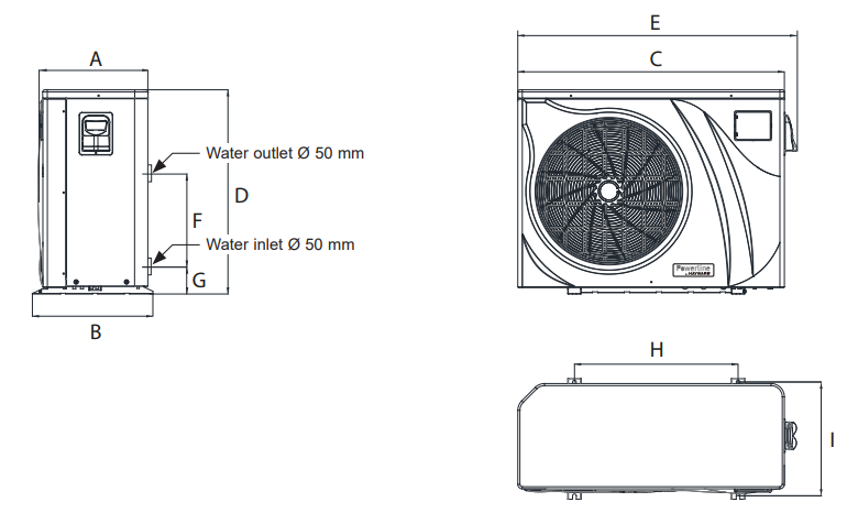
Unit: mm
Installation & Connection
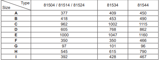
Functional Diagram
 Heat pump unit
 Heat pump unit
Place the heat pump outdoors and away from any enclosed technical space. Placed under a shelter, the minimum required distances mentioned below must be respected to avoid any risk of air recirculation and a deficiency in the unit’s overall performance.
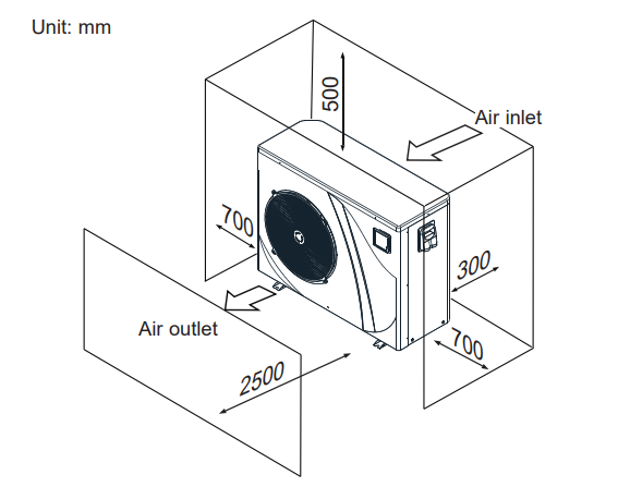
It is advised to install the unit on a dissociated cement block or a mounting bracket designed for this use and to set up the unit on the supplied rubber bushing (fastenings and washers not supplied). The maximum installation distance between the unit and the swimming pool is 15 metres.
Hydraulic connection
The unit is supplied with two 50 mm Ø union connections. Connect the water inlet to the heat pump coming from the filtration group, then connect the water outlet to the heat pump at the water conduit going to the pool (see diagram below). Install a bypass valve between the heat pump entrance and exit.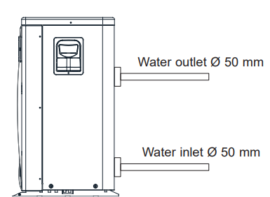
If an automatic distributor or an electrolyser is used, it should be installed immediately after the heat pump to protect the titanium condenser against an elevated concentration of chemicals. Be sure to install the bypass valve and the supplied union connections at the water inlet and outlet levels in order to simplify purging during the winter period and to facilitate access when disassembling for maintenance.
Electrical connection
Electrical installation and wiring for this equipment must be in conformity with local installation standards.
| F | NF C15-100 | GB | BS7671:1992 |
| D | DIN VDE 0100-702 | EW | EVHS-HD 384-7-702 |
| A | ÖVE 8001-4-702 | H | MSZ 2364-702/1994/MSZ 10-553 1/1990 |
| E | UNE 20460-7-702 1993, RECBT ITC-BT-31 2002 | M | MSA HD 384-7-702.S2 |
| IRL | Wiring Rules + IS HD 384-7-702 | PL | PN-IEC 60364-7-702:1999 |
| I | CEI 64-8/7 | CZ | CSN 33 2000 7-702 |
| LUX | 384-7.702 S2 | SK | STN 33 2000-7-702 |
| NL | NEN 1010-7-702 | SLO | SIST HD 384-7-702.S2 |
| P | RSIUEE | TR | TS IEC 60364-7-702 |
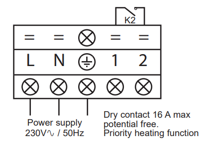
Verify that the available electrical power supply and the network frequency correspond to the required operating current, taking into account the appliance’s specific location, and the current required to supply any other appliance connected to the same circuit. 81504 / 81514 / 81524 / 81534 / 81544 230V +/- 10 % 50 Hz 1 Phase See the corresponding wiring diagram in the appendix. The connection box is located on the right side of the unit. Three connections are designed for the power supply, and two are for controlling the filter pump (Enslavement).
| Models | 81504 | 81514 | 81524 | 81534 | 81544 | |
| Power supply | V/Ph/Hz | 230V 50Hz | 230V 50Hz | 230V 50Hz | 230V 50Hz | 230V 50Hz |
| aM type fuse calibre | A | 8 aM | 10 aM | 12 aM | 20 aM | 20 aM |
| Curve D circuit breaker | A | 8 D | 10 D | 12 D | 20 D | 20 D |
| Cable section | mm2 | 3G 2,5 | 3G 2,5 | 3G 2,5 | 3G 4 | 3G 4 |
Use an RO 2V/R 2V or equivalent power cord. The cable sections are given for a maximum length of 25 m. They must, however, be checked and adjusted according to the installation conditions. Always shut down the main power supply before opening the electrical control box..
Initial start-up
- Rotate the fans by hand to verify that they can turn freely by hand, and that the turbine is correctly affixed to the motor shaft.
- Ensure that the unit is connected correctly to the main power supply (see the wiring diagram in the appendix).
- Activate the filtration pump.
- Verify that all water valves are open and that the water flows toward the unit before switching on the heating or cooling mode.
- Verify that the drainage hose is correctly affixed and that it causes no obstructions.
- Activate the unit power supply, then press the On/Off button on the control panel.
- Make sure the alarm or lock symbols are not displayed. If need be, see the troubleshooting guide (see § 6.4).
- Set the water flow using the by-pass valve (see § 3.6 and 2.1), as provided for by each model, to obtain an Entry/Exit temperature of 2°C.
- After running for several minutes, verify that the air exiting the unit is cool (between 5 and 10°).
- With the unit operating, turn off the filter pump. The unit should automatically turn off and display error code E03
Overview
The heat pump is fitted with an electronic control panel, electronically connected and pre-set at the factory to heating mode.
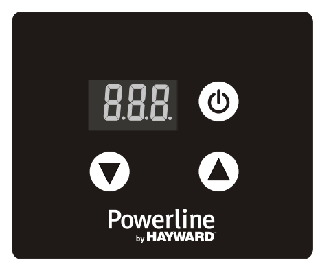
Legend
- On/Off and Return button
- Scroll down
- Scroll up
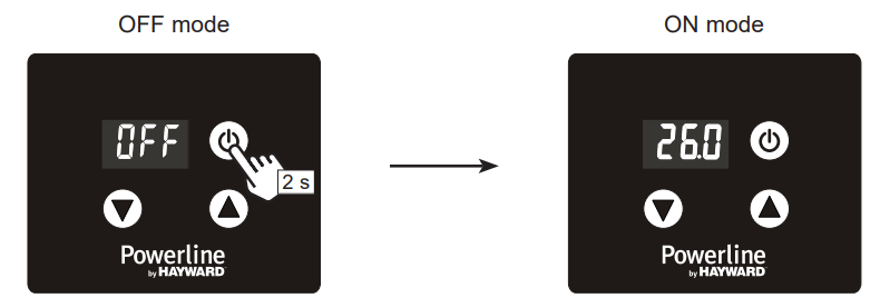
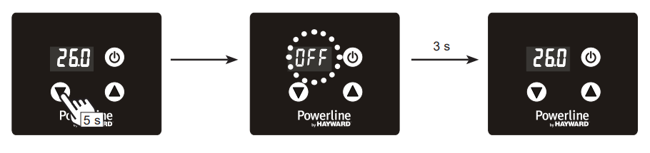
OFF mode
When the heat pump is on standby (OFF mode), the indication OFF is displayed on the control screen.
ON mode
When the heat pump is running or adjusting (ON mode), the water inlet temperature is displayed on the screen.
In OFF mode and in ON mode
Press the button once to view the set point. Press the button to set the desired set point. Settings are made to an accuracy of 0.5 °C.
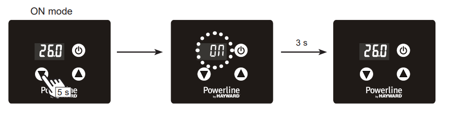
Locking and unlocking the touch screen
Press the On/Off button for 5 seconds until it beeps. The buttons become
inactive. To unlock, press for 5 seconds until it beeps. The buttons become active again.
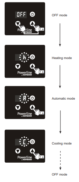
Operating mode selection
Water flow setting
While the heat pump is running and the water inlet and outlet valves are open, adjust the by-pass valve to obtain a difference of 2°C between the water inflow and outflow temperature (see Functional Diagram Section 3.1). You can check the setting by viewing the inflow and outflow temperatures directly on the control panel by following the procedure below.
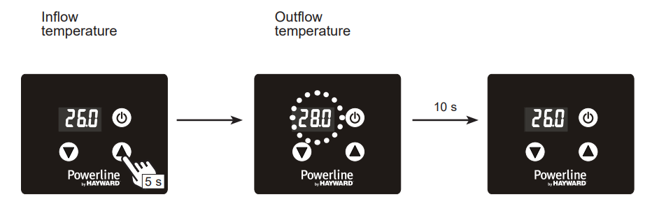
Then adjust the bypass to obtain a difference of 2°C between the inflow and the outflow. Press once to exit the menu.
Activation
Deactivation
Maintainance
- Clean the coil with the help of a soft brush, or a jet of air or water (Warning: never use a high-pressure cleaner).
- Verify that the drains flow well.
- Verify the tightening of the hydraulic and electrical connections
- Verify the hydraulic sealing of the condenser.
- Have the leak-tightness of the cooling circuit to the leak detector checked by an accredited professional.
Winterising
- Put the heat pump in “OFF” mode.
- Cut the power supply to the heat pump.
- Empty the condenser with the help of the drain to avoid any risk of deterioration. (high risk of freezing).
- Close the bypass valve and unscrew the entry/exit connection unions.
- Eliminate the maximum amount of residual stagnant water from the condenser with the help of an air gun.
- Close the water entry and exit areas of the heating pump to avoid introducing foreign bodies.
- Cover the heating pump with a dedicated winterising case.
APPENDIX
Electrical diagrams
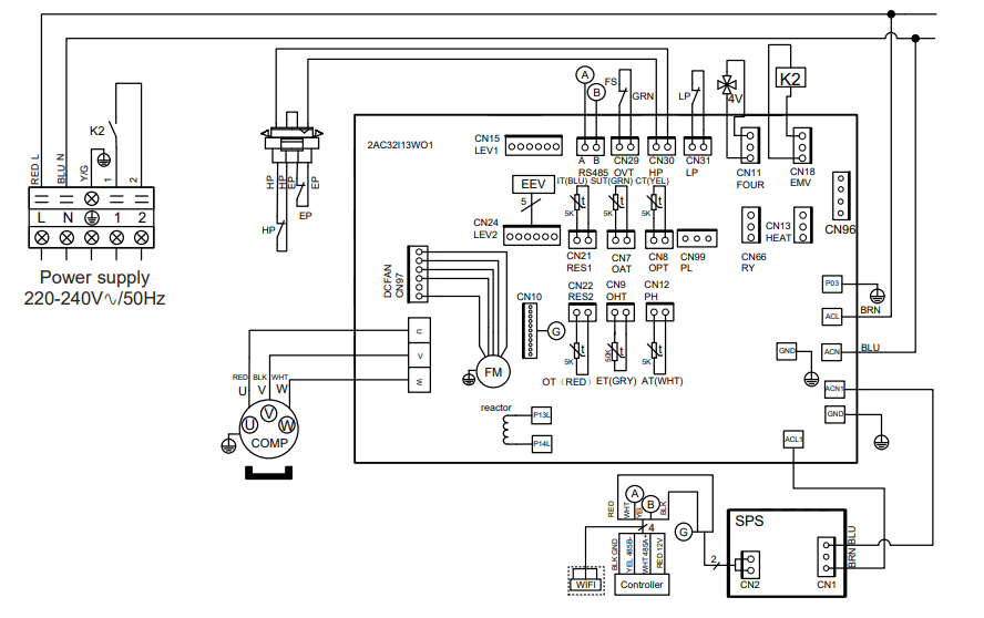
REMARKS
- AT AIR TEMPERATURE SENSOR
- COMP: COMPRESSOR
- CT: EVAPORATOR TEMPERATURE SENSOR
- EEV: ELECTRONIC EXPANSION VALVE
- FM: FAN MOTOR
- FS: WATER FLOW SWITCH
- HP: HIGH PRESSURE SWITCH
- IT WATER INLET TEMPERATURE Hayward R32 Swimming Pool Heat Pump Unit SENSOR
- EP: THERMAL PROTECTION
- LP:L OW PRESSURE SWITCH
- OT: UTLET WATER TEMPERATURE SENSOR
- SUT: SUCTION TEMPERATURE SENSOR
- 4V: 4 WAYS VALVE
- K2: DRY CONTACT 16 A MAX
- ET: DISCHARGE TEMPERATURE SENSOR
- 1: OPTION
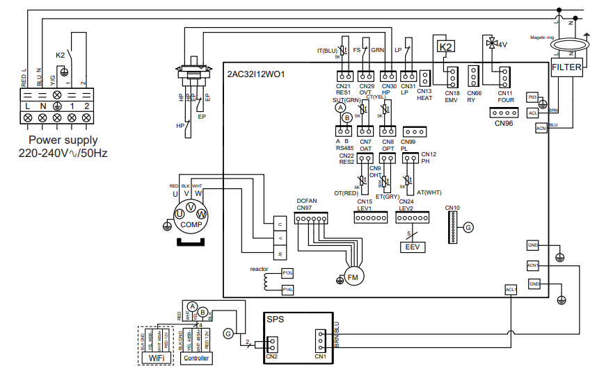
- AT: AR TEMPERATURE SENSOR
- COMP: COPRESSOR
- CT: EVAORATOR TEMPERATURE Hayward R32 Swimming Pool Heat Pump Unit SENSOR
- EEV: ELECTRONIC EXPANSION VALVE
- FM: FAN MTOR
- FS: WATER LOW SWITCH
- HP: HIGH PRESSURE SWITCH
- IT: WATER INET TEMPERATURE Hayward R32 Swimming Pool Heat Pump Unit SENSOR
- EP: THERMAL PROTECTION
- LP LOW PRESSURE SWITCH
- OT: OUTLET WATER TEMPERATURE SENSOR
- SUT: SUCTION TEMPERATURE SENSOR
- 4V: WAYS VALVE
- K2: DRY CONTACT 16 A MAX
- ET: DISCHARGE TEMPERATURE SENSOR
- *: OPTION
Heating priority wiring for monophasic pump
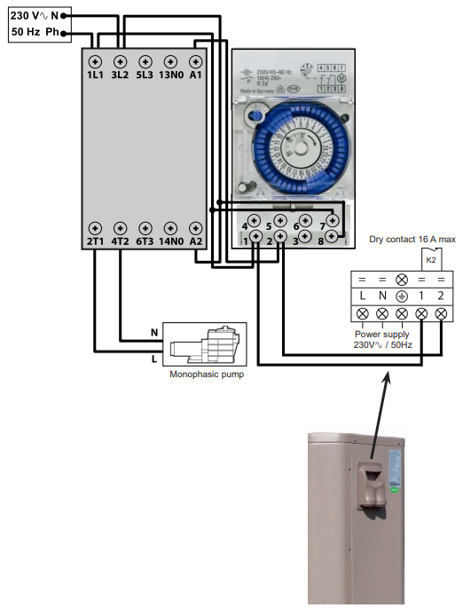
Terminals 1 and 2 deliver a potential-free dry contact, 230V / 50 Hz, no polarity. Wire terminals 1 and 2 as indicated in the diagram above, to activate the operation of the filtration pump in 2-minute cycles each hour if the temperature of the pool is lower than the set point. Never connect the power supply of the filtration pump directly to terminals 1 and 2.
Exploded view and spare parts / Addendum

| Mark | Description | Ref. | 81504 | 81514 | 81524 | 81534 | 81544 |
| 1 | Front panel | HWX80900556 | a | a | a | n/a | n/a |
| HWX80900557 | n/a | n/a | n/a | a | n/a | ||
| HWX80900581 | n/a | n/a | n/a | n/a | a | ||
| 2 | 3-button controller | HWX95005310598 | a | a | a | a | a |
| 3 | Fan protection grille | HWX80900375 | a | a | a | n/a | n/a |
| HWX20000220369 | n/a | n/a | n/a | a | a | ||
| 4 | Fan blade | HWX301030000006 | a | a | a | n/a | n/a |
| HWX301030000001 | n/a | n/a | n/a | a | a | ||
| 5 | / | / | / | / | / | / | / |
| 6 | DC ventilator motor | HWX80200018 | a | a | a | n/a | n/a |
| HWX20000330132 | n/a | n/a | n/a | a | a | ||
| 7 | 16A 50Hz 5mH Coil | HWX82500006 | a | a | a | n/a | n/a |
| 20A 50Hz 5.2mH Coil | HWX82500005 | n/a | n/a | n/a | a | a | |
| 8 | Left panel | HWX80700446 | a | a | a | n/a | n/a |
| HWX80700315 | n/a | n/a | n/a | a | n/a | ||
| HWX80700355 | n/a | n/a | n/a | n/a | a | ||
| 9 | Fin coil | HWX301060202502 | a | n/a | n/a | n/a | n/a |
| HWX80600042 | n/a | a | n/a | n/a | n/a | ||
| HWX80600043 | n/a | n/a | a | n/a | n/a | ||
| HWX80600044 | n/a | n/a | n/a | a | n/a | ||
| HWX80600078 | n/a | n/a | n/a | n/a | a | ||
| 10 | Motor bracket | HWX80700218 | a | a | a | n/a | n/a |
| HWX80700248 | n/a | n/a | n/a | a | n/a | ||
| HWX80700329 | n/a | n/a | n/a | n/a | a | ||
| 11 | / | / | / | / | / | / | |
| 12 | Top cover | HWX80900055 | a | a | a | n/a | n/a |
| HWX80900255 | n/a | n/a | n/a | a | n/a | ||
| HWX80900371 | n/a | n/a | n/a | n/a | a | ||
| 13 | / | / | / | / | / | / | |
| 14 | / | / | / | / | / | / | / |
| 15 | Low pressure switch NO 0.30MPa/0.15MPa | HWX20000360157 | a | a | a | a | a |
| 21 | |||||||
Addendum
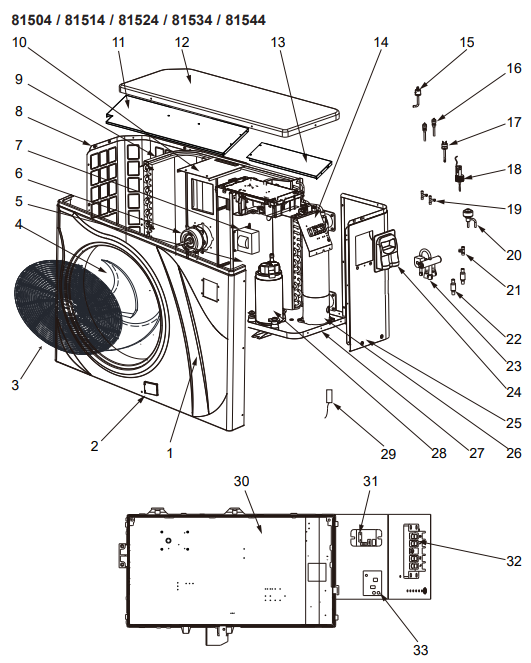
| Mark | Description | Ref. | 81504 | 81514 | 81524 | 81534 | 81544 |
| 29 | Compressor aspiration sensor 5k-560mm | HWX83000044 | a | a | a | n/a | n/a |
| Compressor aspiration sensor 5k-760mm | HWX83000053 | n/a | n/a | n/a | a | a | |
| Ambiente temp sensor 5k-350mm | HWX83000049 | a | a | a | a | a | |
| Water outlet sensor 5k-410mm | HWX83000050 | a | a | a | a | a | |
| Water inlet sensor 5k-850mm | HWX83000052 | a | a | a | a | n/a | |
| Water inlet sensor 5k-980mm | HWX83000055 | n/a | n/a | n/a | n/a | a | |
| Compressor discharge probe 50k-660mm | HWX83000026 | a | a | a | a | a | |
| De-icing sensor 5k-680mm | HWX83000051 | a | a | a | n/a | n/a | |
| De-icing sensor 5k-1040mm | HWX83000045 | n/a | n/a | n/a | a | a | |
| 30 | Printed circuit board Driver | HWX82300152 | a | a | a | n/a | n/a |
| HWX82300007 | n/a | n/a | n/a | a | a | ||
| 31 | K2 relay | HWX20000360297 | a | a | a | a | a |
| 32 | Terminal block L-N-GND -5 connections 4mm² | HWX40003901 | a | a | a | a | a |
| 33 | 230V/12VDC transformer | HWX82600008 | a | a | a | a | a |
Troubleshooting
| Problem | Error codes | Description | Solution |
| Water inlet sensor fault | P01 | The sensor is open or has short-circuited. | Verify the CN21/RES1 connectors on the board and the extension connector, or replace the sensor |
| Water outlet sensor fault | P02 | Verify the N22/RES2 connectors on the board and the extension connector, or replace the sensor. | |
| Outside temperature sensor fault | P04 | Verify the CN12/PH connectors on the board and the extension connector, or replace the sensor. | |
| De-icing sensor fault | P05 | Verify the CN8/OPT connectors on the board and the extension connector, or replace the sensor. | |
| Compressor aspiration sensor defect | P07 | Verify the CN7/OAT connectors on the board and the extension connector, or replace the sensor. | |
| Compressor discharge sensor fault | P081 | Verify the CN9/OHT connectors on the board and the extension connector, or replace the sensor. | |
Warranty
HAYWARD’s warranty is limited to the repair or replacement, at HAYWARD’s discretion, of faulty products, provided they have been used under normal conditions, Hayward R32 Swimming Pool Heat Pump Unit as described in their user guide, and that the product has not been modified in any way and has been used only with HAYWARD components and parts.
Customer Service
- Ph: 1-800-657-2287
- Website: www.haywardcommercialpool.com
FAQs
What is R32 refrigerant, and why is it important?
Compared to earlier refrigerants, R32 is a more recent, energy-efficient refrigerant with a lower global warming potential (GWP). It lessens its impact on the environment while improving performance.
How does the heat pump work?
It works by drawing in outside air, using a refrigerant cycle to extract heat, and then using a heat exchanger to transmit that heat to the water in your pool. Above 45°F (7°C), ambient temperatures are ideal for its operation.
Can I install the R32 unit indoors?
No. To guarantee optimal airflow and efficiency, it must be placed outdoors in a well-ventilated space with sufficient clearance, usually 20 to 40 inches on all sides.
What is the ideal water temperature setting?
Although preferred pool temperatures vary, 78°F to 82°F (25°C to 28°C) is a typical range. If necessary, the device can normally heat up to 95°F (35°C).
How long does it take to heat the pool?
The size of the pool, the air temperature, and the initial water temperature all affect it. Under perfect circumstances, it can increase the water’s temperature by 1 to 2°F every day on average.