
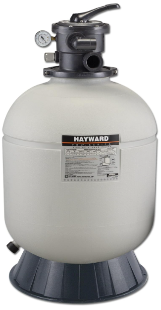
Hayward S144T Series High Rate Sand Filter
Safety Instructions
- Do not operate the water circulation system if a system component is assembled improperly, damaged, missing, or not a genuine Hayward component.
- Before performing maintenance on the water circulation system, verify that all system and pump controls are in the OFF position and the filter manual air relief valve is in the OPEN position.
- Use ONLY Hayward clamp system components: DEX2421JKIT clamp assembly, DEX2421J2 nut/bolt assembly, and a DEX2422Z2 metal reinforced seal. Non-Hayward components may fail in use and cause explosive separation.
- Never rely on hand-tightening the clamp nut to the clamp bolt. Using a ¾” socket on a torque wrench, torque the clamp nut and clamp bolt to 150 inch-lbs.
- Before starting the system pump, ensure the filter manual air relief valve body is in the LOCK position in the filter upper body.
- Before starting the system pump, verify that all system valves are set in a position to allow water from the filter to return to the pool.
- Before starting the system pump, the manual air relief valve must be in the OPEN position.
- When starting the pump, do not stand over or near the filter.
- If water leakage appears in the area of the filter tank clamp, immediately turn off all system circulation pumps and electrical power. Do not return to the filter until all water flow has stopped. Reassemble the clamp system per the instructions in this owner’s manual to stop the leak.
- Return to filter to close the manual air relief valve only when a steady stream of water (Not air or air and water mix) is discharged from the manual air relief valve.
- Do not change the filter control valve position while the system pump is running.
Introduction
Your Hayward Pro Series™ high-rate sand filter is a high-performance, totally corrosion-proof filter that blends superior flow characteristics and features with ease of operation. It represents the very latest in high-rate sand filter technology. It is virtually foolproof in design and operation, and when installed, operated, and maintained according to instructions, your filter will produce clear, sparkling water with only minimal attention and care.
How It Works
Your filter uses special filter sand to remove dirt particles from pool water. Filter sand is loaded into the filter tank and functions as the dirt-removing media. The pool water, which contains suspended dirt particles, is pumped through your piping system and is automatically directed by the filter control valve to the top of the filter tank.
As the pool water is pumped through the filter sand, dirt particles are trapped by the sand bd, and filtered out. The cleaned pool water is returned from the bottom of the filter tank, through the control valve, and back to the pool through the piping system.
This entire sequence is continuous and automatic and provides recirculation of pool water through your filter and piping system. After a period of time, the accumulated dirt in the filter causes a resistance to flow, and the flow diminishes. This means it is time to clean (backwash) your filter.
With the control valve in the backwash position, the water flow is automatically reversed through the filter so that it is directed to the bottom of the tank, up through the sand, flushing the previously trapped dirt and debris out the waste line. Once the filter is backwashed (cleaned) of dirt, the control valve is manually re-sequenced to Rinse, and then Filter, to resume normal filtering.
Installation
Only simple tools (screwdriver and wrenches), plus pipe sealant for plastic adapters, are required to install and/or service the filter.
Installation Steps
- The filter system should be installed, not more than 6 feet above pool water level, on a level concrete slab, very firm ground, or equivalent, as recommended by your pool dealer. Position the filter so that the piping connections, control valve, and winter drain are accessible for operation, service, and winterizing.
- Assemble the ump mounting base (if supplied) to the filter according to the instructions packed with the base.

- Loading sand media. Filter sand media is loaded through the top opening of the filter.
- Loosen flange clamp and remove Filter Control Valve (if previously installed). Cap the internal pipe with a sand shield to prevent sand from entering it. Be sure the pipe is securely in place in the bottom underdrain hub.
- We recommend filling the tank approximately 1/2 way with water to provide a cushioning effect when the filter sand is poured in. This helps protect the underdrain laterals from excessive shock. (Be sure the winter drain cap is securely in place on the drain pipe.)
- Carefully pour in the correct amount and grade of filter sand, as specified in the Specifications table on page 11. (Be sure the center pipe remains centered in the opening.) Because filter sand is not all the same. THE LEVEL OF SAND MUST REMAIN A MINIMUM OF 10” FROM THE TOP. Remove the sand shield from the internal pipe.
Refer to the image on the following page for a typical installation.
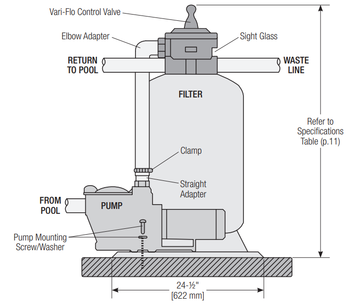
Assemble the Filter Control Valve to the filter tank.
- Loosely pre-assemble both halves of the clamp with one screw and one nut, turning the nut 2 or 3 turns. Do not tighten. Wipe the filter flange clean.
- Insert the Filter Control Valve (with valve/flange 0-ring in place) into the tank neck, taking care that the center pipe slips into the hole in the bottom of the valve. Install a clamp around the tank and valve flange, and assemble the second screw and nut. Tighten just enough so that the valve may be rotated on the ank for final positioning.
- Wrap two turns of Teflon pipe sealant tape manufactured for plastic pipe on the ¼” NPT male end of the gauge. Carefully screw the pressure gauge into the 1/4″ NPT tapped hole in the valve body. Do not over-tighten.
- Connect the pump to the control valve opening marked PUMP according to instructions. After connections are made, tighten the valve flange clamp with a screwdriver, tapping around the clamp with the screwdriver handle to help seat the valve flange clamp.
- Return to the pool pipe connection to the control valve opening marked RETURN and complete
other necessary plumbing connections, suction lines to pump, waste, etc. - Make electrical connections to the pump per the pump instructions.
- To prevent water leakage, be sure the winter drain cap is securely in place and all pipe connections are tight.
Initial Start-Up of Filter
- Be sure the correct amount of filter sand media is in the tank and that all connections have been made and are secure.
- Depress the Vari-Flo control valve handle and rotate to the BACKWASH position. (To prevent damage to the control valve seal, always depress the handle before turning.) For new concrete or gunite pools, or where there is a large amount of plaster dust or debris, start filter in FILTER position (not BACKWASH) to prevent clogging of under-drain laterals.
- Prime and start the pump according to pump instructions (be sure all suction and return lines are open), allowing the filter tank to fill with water.
- Turn the pump off and set the valve to the RINSE position. Start the pump and operate until the water in the sight glass is clear—about 1/2 to 1 minute. Turn the pump off, set the valve to the FILTER position, and restart the pump. Your filter is now operating in the normal filter mode, filtering particles from the pool water.
- Adjust pool suction and return valves to achieve the desired flow. Check the system and filter for water leaks and tighten connections, bolts, and nuts, as required.
- Note the initial pressure gauge reading when the filter is clean. (It will vary from pool to pool depending upon the pump and general piping system.) As the filter removes dirt and impurities from the pool water, the accumulation in the filter will cause the pressure to rise and the flow to diminish. When the pressure gauge reading is 8-10 PSI (0.55-0.69 BAR) higher than the initial “clean” pressure you noted, it is time to backwash (clean) the filter (see BACKWASH under Filter Control Valve Functions).
Operation
- FILTER: Set valve to FILTER for normal filtering. Also, use for regular vacuuming.
- BACKWASH: For cleaning the filter. When the filter pressure gauge rises 8-10 PSI (0.55-0.69 BAR) above
- start-up (clean pressure): Stop the pump, set the valve to BACKWASH. Start the pump and backwash until the water in the sight glass is clear. Approximately 2 minutes or less, depending on dirt accumulation. Proceed to RINSE.
- RINSE: After backwashing, with pump off, set valve to RINSE. Start the upump and operate for about 1/2 to 1 minute. This ensures that all dirty water from backwashing is rinsed out of the filter to waste, preventing possible return to the pool. Stop pump, set valve to FILTER, and start pump for normal filtering.
- WASTE: To bypass the filter for draining or lowering the water level and for vacuuming heavy debris directly to waste. RECIRCULATE—Water is recirculated through the pool system, bypassing the filter.
- CLOSED: Shuts off the flow from the pump to the filter. VACUUMING—Vacuuming can be performed directly into the filter. When vacuuming heavy debris loads, set the valve to the WASTE position to bypass the filter and vacuum directly out to waste.
Winterization
- Completely drain the tank by unscrewing the drain cap at the base of the filter tank. Leave the cap off during winter.
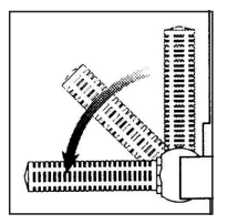
- Depress the Vari-Flo control valve handle and rotate so as to set the pointer on the valve top between any two positions. This will allow water to drain from the valve. Leave the valve in this “inactive” position.
- Drain and winterize the pump according to the pump instructions.
Replacement Parts
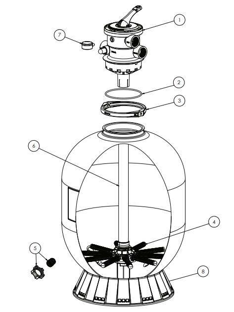
| Ref No | Part No | Description | Qty |
| 1a | SP0714T | 1.5″ VariFlo XL Control Valve | 1 |
| 1b | SP071620T | 2″ VariFlo XL Control Valve | 1 |
| 2 | GMX600F | Valve/Tank Oring | 1 |
| 3a | GMX600NM | Flange Clamp (Plastic) | 1 |
| 3b | SX310N | Flange Clamp (Stainless Steel) | 1 |
| 4a | SX200QNRPAK10 | 16″, 18″, 21″, 22″ Lateral ribbed (10) | 1 |
| 4b | SX240DNRPAK10 | 24″, 27″ lateral ribbed end (10) | 1 |
| 4c | SX310HNRPAK10 | 30″, 36″ lateral ribbed end (10) | 1 |
| 5a | SX180HG | Drain Cap Kit (Round) | 1 |
| 5b | SX180LA | Drain Cap Assy | 1 |
| 6a | SX164DAS | Folding Lateral Assembly 16″ with standpipe | 1 |
| 6b | SX180DAS | Folding Lateral Assembly 18″ with standpipe | 1 |
| 6c | SX210DAS | Folding Lateral Assembly 21″ with standpipe | 1 |
| 6d | SX210DA2S | Folding lateral assembly 21″ T2 with 2″ standpipe | 1 |
| 6e | SX220DAS | Folding Lateral Assembly 22″ with standpipe | 1 |
| 6f | SX220DA2S | Folding lateral assembly 22″ T2 with 2″ standpipe | 1 |
| 6g | SX244DAS | Folding Lateral Assembly 24″, with standpipe | 1 |
| 6h | SX244DA2XS | Folding Lateral Assembly 24″ T2 with 2″ standpipe | 1 |
| 6j | SX270DA2S | Folding lateral Assembly 27″ with standpipe | 1 |
| 6k | SX270DA2XS | Folding Lateral Assembly 27″ T2 with 2″ standpipe | 1 |
| 6m | SX310DA2S | Folding Lateral Assembly 31″ with standpipe | 1 |
| 6n | SX360DAS | Folding Lateral Assembly 36″ with standpipe | 1 |
| 7 | ECX270861 | Pressure Gauge | 1 |
| 8a | SX164B | 14″ and 16″ Filter Base | 1 |
| 8b | SX200J | 18″-27″ Filter Base | 1 |
| 8c | SX310J | 30″&36″ Filter Base | 1 |
| 9a | SX164C | 14″ and 16″ Pump Base | 1 |
| 9b | SX180J | System base 18″, 21″, 23″ | 1 |
| 10 | ECX1108A | Pump mounting screw kit | 1 |
| 11a | SX160Z4KIT | 26″ Hose Kit (14″, 16″ system) | 1 |
| 11b | SX201Z1KIT | 33″ Hose Kit (18″, 21″, 23″ System) | 1 |
Maintenance
Consult your local authorized Hayward dealer or service center. No returns may be made directly to the factory without the express authorization of Hayward Pool Products, Inc.
Performance
Pure, clear swimming pool water is a combination of two Hayward S144T Series High Rate Sand Filter factors—adequate filtration and proper water chemistry balance. One without the other will not give the clean water you desire. Your filter system is designed for continuous operation. However, this is Hayward S144T Series High Rate Sand Filter not necessary for most swimming pools. You can determine your filter operation schedule based on your pool size and usage. Be sure to operate your filtration system long enough each day to obtain at least one Hayward S144T Series High Rate Sand Filter complete turnover of your pool water.
To properly sanitize your pool, maintain a free chlorine level of 1 to 3 ppm and a pH range of 7.2 to 7.6. Insufficient chlorine or an out-of-balance pH level will permit algae and bacteria to grow in your pool and make it difficult for your filter to properly clean the pool water.
Specifications
| Model No. | Effective Filtration Area | Maximum Working Pressure | Required Clearance | Media Capacity | Installed Height | ||||||||
| Side | Above | Type | Amount | ||||||||||
| ft2 | m2 | PSI | BAR | in. | mm | in. | mm | Filter Sand* | lbs | kg | in. | mm | |
| S144T | 1.1 | .10 | 50 | 3.45 | 18 | 460 | 18 | 460 | 0.45 – 0.55 mm | 50 | 22 | 32 | 815 |
| S166T | 1.4 | .13 | 50 | 3.45 | 18 | 460 | 18 | 460 | 0.45 – 0.55 mm | 100 | 45 | 33 | 840 |
| S180T | 1.8 | .17 | 50 | 3.45 | 18 | 460 | 18 | 460 | 0.45 – 0.55 mm | 150 | 68 | 35 | 890 |
| S210T | 2.2 | .20 | 50 | 3.45 | 18 | 460 | 18 | 460 | 0.45 – 0.55 mm | 200 | 90 | 38 | 965 |
| S210T2 | 2.2 | .20 | 50 | 3.45 | 18 | 460 | 18 | 460 | 0.45 – 0.55 mm | 200 | 90 | 38 | 965 |
| S220T | 2.6 | .25 | 50 | 3.45 | 18 | 460 | 18 | 460 | 0.45 – 0.55 mm | 250 | 115 | 41 | 1040 |
| S220T2 | 2.6 | .25 | 50 | 3.45 | 18 | 460 | 18 | 460 | 0.45 – 0.55 mm | 250 | 115 | 41 | 1040 |
| S244T | 3.1 | .29 | 50 | 3.45 | 18 | 460 | 18 | 460 | 0.45 – 0.55 mm | 300 | 135 | 42 | 1070 |
| S244T2 | 3.1 | .29 | 50 | 3.45 | 18 | 460 | 18 | 460 | 0.45 – 0.55 mm | 300 | 135 | 42 | 1070 |
| Maximum Recommended System Flow Rate By Pipe Size | ||||||||
| Pipe Size in. [mm] | Flow Rate GPM [LPM] | Pipe Size in. [mm] | Flow Rate GPM [LPM] | Pipe Size in. [mm] | Flow Rate GPM [LPM] | |||
| 1 [32] | 20 [75] | 1-1/2 [50] | 45 [170] | 2-1/2 [75] | 110 [415] | |||
| 1-¼ [40] | 30 [110] | 2 [63] | 80 [300] | 3 [90] | 160 [600] | |||
| Suggested Pool Chemistry | ||||||||
| pH | 7.2 to 7.6 | |||||||
| Total Alkalinity | 80 to 120 ppm | |||||||
| Calcium Hardness | 200 to 400 ppm | |||||||
| Combined Chlorine | 0.2 ppm Maximum | |||||||
| Chlorine (Stabilized) | 1.0 to 3.0 ppm | |||||||
| Stabilizer (Cyanuric Acid) | 60 to 80 ppm | |||||||
Troubleshooting
| Problem Solving List | |||
| Problem | Low Water Flow | Short Filter Cycles | Pool Water Won’t Clear Up |
| Remedy | • Check skimmer and pump strainer baskets for debris. • Check for restrictions in intake and discharge lines. • Check for an air leak in the intake line (indicated by bubbles returning to the pool). • Backwash filter. | • Check for algae in the pool and superchlorinate as required. • Be sure chlorine and pH levels are in the proper range (adjust as required). • Check surface of filter sand for crusting or caking (remove 1 ” of sand if necessary). | • Check chlorine, pH, and total alkalinity levels and adjust as required. • Be sure the flow rate through the filter is sufficient. • Operate the filter for longer periods. • Be sure the Vari-Flo valve is set on the “Filter” position. |
HAYWARD® Pool Products Limited Warranty
Hayward Pool Products, Inc., warrants the components of this product to be free from defects in materials and workmanship during the warranty period. Please visit https://hayward.com/support/resources/warranty for product warranty details. The limited warranty Hayward S144T Series High Rate Sand Filter excludes damage from freezing, negligence, improper installation, improper use or care, Acts of God, or as specified in installation and operations manual.
In the event proof of purchase is not available, the manufacturing date of the product will be the sole determination of the purchase date. To obtain warranty Hayward S144T Series High Rate Sand Filter service, please contact the place of purchase or the nearest Hayward Authorized Service Center. For assistance at your nearest Hayward Authorized Service Center, please visit us at https://hayward.com/dealerlocator.
Hayward shall not be responsible for cartage, removal, repair, or installation labor, or any other such costs incurred in obtaining warranty replacements or repair. The Hayward Pool products’ warranty does not apply to components manufactured by others. For such products, the warranty established by the respective manufacturer will apply.
In no event shall Hayward Pool products be responsible for any consequential, incidental, or indirect damages of any nature.
Some states do not allow a limitation on how long an implied warranty lasts, or the exclusion of incidental or
consequential damages, so the above limitation may not apply to you. This warranty gives you specific legal rights, and you may also have other rights, which vary from state to state. Hayward Industries, 1415 Vantage Park Dr., Suite 400, Charlotte, NC 28203 *Supersedes all previous publications
Register your product at https://hayward.com/support/resources/warranty/product-registration
For further information or consumer technical support, visit our website at www.hayward.com
Customer Service
- Ph: 1-800-657-2287
- Website: www.haywardcommercialpool.com
FAQs
What is the primary function of the S144T sand filter?
By filtering the water using sand media, the S144T Series filter removes dirt and debris, leaving the pool water clear and clean.
2. How much sand does the S144T filter require?
About 125 lbs (57 kg) of #20 grade silica sand are needed for the filter. For the best filtration, use only the type of sand that is suggested.
How often should I backwash the filter?
When the water clarity decreases or the pressure gauge indicates 8–10 psi over the clean filter pressure, backwash the filter.
Can I add chemicals directly to the sand filter?
No. To avoid harming the sand media and filter elements, chemicals should always be added straight to the pool water.
Can I use the S144T filter with a saltwater pool?
The S144T filter can be used in saltwater pools; however, regular inspection is necessary to avoid deterioration from exposure to salt.
Is the S144T filter resistant to heat and UV exposure?
Indeed, the components and tank are made to withstand normal pool temperatures and UV radiation, making them suitable for outdoor use.
How do I replace the multiport valve?
For information on replacing and removing valves, consult the user manual. To stop leaks, make sure the gaskets are aligned and sealed properly.