
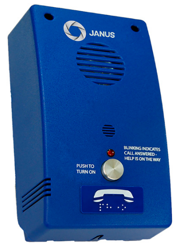
JANUS ADA Telephone Line Powered
Installation
Box-Less (PNB)
- Mount the phone on the car station.
- Attach the red lens cap and bezel to the ¼” hole on the car station.
- Insert the LED into the lens cap and plug the wire into P6.
- 2 LED versions – Red LED goes to “Call in Progress” (P6), Green LED goes to “Alarm Received” (P5)
- Attach emergency button leads to the terminal block at P2 (EXT ON/OFF).
- Attach the phone line to the terminal block at P1 (TELCO) or the P1A modular phone jack.
Box Style (PBX)
- Mount the back box into the phone cabinet in the car station.
- Allow enough room at the bottom for opening and removing the phone cover.
- Attach the phone line to the terminal block at P1 (TELCO) or the P1A modular phone jack.
- Attach the phone cover with the screws provided.
Flush Mount Style (PSS/PSL)
- Cut a 5 x 9-inch hole for the phone.
- Using the plate as a template, mark and drill holes for the mounting screws.
- Attach the phone line to the terminal block at P1 (TELCO) or the P1A modular phone jack.
- Mount phone (screws not provided).
Surface Mount Style (PSM)
- Use the mounting plate as a template.
- Attach the mounting plate to the wall.
- Attach the phone line to the terminal block at P1 (TELCO) or the P1A modular phone jack.
- Attach the phone cover with the screws provided.
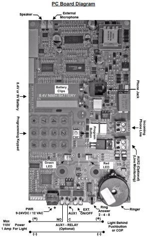
PC Board Diagram
Programming Set-Up Methods
There are two methods of setting up the hands-free elevator phone for programming. Select the one applicable to your situation as described below.
Method A: Calling the elevator phone to program it.
- From a touch-tone phone, call the phone number to which the elevator phone is connected.
- After four rings (OR if the “CALL” button is pressed), the elevator phone will turn on automatically, and you will hear a diddle-diddle-diddle sound.
- Go to the “Programming Instructions” section.
- After programming the phone, you should test it by pressing the “CALL” button. The test will ensure the phone is functioning correctly and as programmed.
Method B: Using the keypad on the board to program it.
- Disconnect the phone line from the P1 connector (TELCO) or the P1A modular phone jack.
- Connect a 9-volt battery to the battery clips on the board. (See diagram of phone board)
- Wait 30 seconds and then press the “PROGRAM” button above the keypad.
- Make sure the red light of the phone turns on. If it does not, go back to step 3 and start again.
- The elevator phone will turn on, and you will hear a diddle-diddle-diddle sound.
- Go to the “Programming Instructions” section.
- When you have completed the programming of the phone, you can unplug the 9-volt battery.
- After programming the phone, you should test it by pressing the “CALL” button. The test will ensure the phone is functioning correctly and as programmed.
Programming Instructions
- Choose programming setup method A or B.
- Enter # 94851 or # 9000000 to enter programming mode. Listen for three beeps.
- Enter # 0 (enter the first phone number to be programmed) * #. Listen for three beeps. EXAMPLE: # 0 5551212 * #.
NOTE: If you are on a phone line that requires a “9” or another digit to call the answering service, enter a # after the 9. This will insert a four-second pause. EXAMPLE: # 09 # 5551212 * #. - Enter # 1 (enter second phone number to be programmed) * #. (Optional)
- Enter # 2 (enter third phone number to be programmed) * #. (Optional)
- Enter # 3 (enter fourth phone number to be programmed) * #. (Optional)
- Enter # 4 (ID Code) * #. (Optional)
- Enter # 7 and listen for the single beep. At the beep, record the location message by speaking into the touch-tone phone handset or into the microphone of the HFP phone when using the keypad to program. Enter 0 to end. If you want to listen to the location message without changing it, enter # 8.
- Enter # * 1180183 * # and listen for three beeps. (Enables voice prompt messages)
- Enter # # to exit programming and hang up the phone.
Optional Programming Instructions
Eliminate Autodialing
- Enter # 94851 or #9000000 and listen for three beeps.
- Enter # 0 * #, listen for three beeps, enter # 1 * #, listen for three beeps.
- Enter # 2 * #, listen for three beeps, enter # 3 * #, listen for three beeps.
- Enter # * 1180180 * #, listen for three beeps. (Optional)
- Enter # # and hang up.
To Disable the Voice Prompt Message
- Enter # 94851 or #9000000 and listen for three beeps.
- Enter # * 1180180 * #, listen for three beeps.
- Enter # # and hang up.
Disable the Voice Prompt Message and Delay the Voice
- Enter: # 94851 or #9000000 and listen for three beeps.
- Enter: # * 1180185 * # and listen for three beeps.
- Enter: # # and hang up.
Enable Voice Prompt Message: (DEFAULT)
- Enter # 94851 or #9000000 and listen for three beeps.
- Enter # * 1180183 * # and listen for three beeps.
To program the location message, see step 8 in the programming instructions. Enter # # and hang up.
Enable Voice Prompt Message: (DEFAULT)
- Enter # 94851 or #9000000 and listen for three beeps.
- Enter # * 1180183 * # and listen for three beeps.
- To program the location message, see step 8 in the programming instructions.
- Enter # # and hang up.
List of Commands for Programming Mode
- #0 First Phone Number *#
- #1 Second Phone Number *#
- #2 Third Phone Number *#
- #3 Fourth Phone Number *#
- #4 Identification Code *#
- #5 Programming New Password *# – Set Programming Access Code
- #7 – Records Location Message
- #8 – Plays back Location Message
- #* 1 XXX Y W Z *# – setup code (Default is: #* 1 180 1 8 3 *#)
- XXX – Call Timer [000,060-990], 000=Disable timer
- Y – Push Button Control [0-2]
- [0] Push on = turn on/push again = play message
- [1] Push on = turn on/push again = turn off
- [2] Push and hold = turn on/release = turn off
- [3-8] Push and hold to turn on for Y amount of seconds to make a call.
- If pushed for less than Y amount of seconds, turn off/push again = turn off
- W – Unit ID [1-8]
- Z – Voice Mode [0,3 or 5]
- 43 X *# – Ring Time (for outgoing calls) (18-60 range, 50 is default)
- 44 X *# – AUX1 Behavior (0-2), 0 = disabled, 1 = red led, 2 = green led, 3 = VCC mode
- 45X*# – Redial, 0 = disabled (Default), 1 = Dial the number 1 more time, 2 = Dial the number 2 more times.
- 8 XX *# – Set Language (1 = English: default, 2 = Spanish, X= [1-2] (must have 2 digits)
Specifications
- Optional AC Adapter: 9 – 24VDC / 12VAC @ min. 200mA
- Power Required: on-hook 0 ma
- Power Required: off-hook 20 to 30mAa
- Phone Line Voltage: on-hook 24 to 70VDC (nominally 48VDC)
- Phone Line Voltage: off-hook 8 to 20VDC (nominally 14VDC)
- Ring Sensitivity: 40 – 120VAC RMS
- Dialing: DTMF (Dual Tone Multi Frequency)
- Frequency Response: 550Hz – 3400Hz, +/- 3db.
- Operational Loop impedance: 600 ohms
- FCC Registration: US: NLFTE05B25668
- Ringer’s Equivalent Number: 0.5B
Auxiliary Outputs Information
AUX1 (optional): The AUX1 output by default will not be active (open). If the user would like to activate this output, they must program code: **44
- X *# – which controls the AUX1 behavior. The letter Xinn, this code could be substituted by 0, 1,2, or 3.
- 0 = Disabled – The AUX1 will stay OPEN.
- 1 = Red LED mode – The AUX1 will close when the Red LED turns ON and Open when the Red LED turns OFF”.
- 2 = Green LED mode – The AUX1 will close when the Green LED turns ON and open when the Green LED turns“OFF”.
- 3 = VCC mode – The AUX1 will close when the phone turns ON and open when the phone turns“OFF”.
- AUX2 (optional): The AUX2 output is used for phone line monitoring. When a good phone line is connected to the uni,,t this output is normally open. If the telephone line drops below 2 volts, is disconnected, or shorted for more than 15 minutes, this output will close.
Battery and Power Supply Information
The following information explains how to determine when a battery or power supply is needed or when to use a specific type of battery: You will need a 9V battery or a 9-24VDC/12VAC power supply with
- The phone drops off the telephone line without completing the call.
- There is more than one phone on the same telephone line, and there is a need to call back to a specific elevator phone, or if all elevator phones need to be “ON” at the same time.
Troubleshooting Guide
- Check the phone line connection
- Check phone line voltage (Normal C.O. line 48-52VDC or 20-35VDC – internal systems)
- Try connecting a fully charged 9-Volt battery
- Make sure the phone line is connected to the screw terminal connector at TELCO or the P1A modular phone jack (see P.C. Board Diagram on page 4)
- Check if the unit is pulling down the line voltage (you should read the same as the phone line voltage)
- Check the voltage at the controller
- Check the button connection
- On an OEM-style phone, the e button connector and try shorting the button connection at P2 EXT- ON/OFF pins
- Check the number programmed into the phone
- Plug a phone into the jack and call the same number you are trying to program to see if you can call out
Customer Support
- Address: Janus Henderson 801 Pennsylvania JANUS Pana40Plus 2D-3D Detector Controller Ave, Suite 219109 Kansas City, MO 64105-1307
- Website: https://www.janushenderson.com
- Tel: 800-525-3713.
- Tomings: Weekdays, 9 a.m. – 6 p.m.
FAQs
Q: What does “line powered” mean?
“Line powered” refers to the fact that, like a conventional analogue phone, the JANUS ADA gets its working power straight from the associated telephone line. Standard functioning doesn’t require any extra batteries or mains electricity.
Q: What type of telephone line is compatible?
The JANUS ADA is intended for use with analogue PBX extensions or conventional PSTN (Public Switched Telephone Network). Although performance may differ, it might also function with some VoIP adapters that offer an analogue line output.
Q: Does the JANUS ADA require a separate power supply?
No, under normal circumstances, neither batteries nor an AC adaptor are needed because the device is self-powered via the phone line.
Q: What happens if the telephone line loses power?
Because the JANUS ADA relies on line voltage, it won’t work if the exchange power fails, the phone line is removed, or it is idle. Use a GSM module or backup line for crucial installations.
Q: Is the device ADA-compliant?
Indeed. When implemented correctly, the JANUS ADA can provide clear two-way voice communications and accessible emergency calling, meeting ADA (Americans with Disabilities Act) communication requirements.