
JANUS LMA-NC Line Monitor Alert

Overview
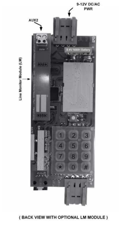
The JANUS LMA-NC Line Monitor Alert board provides visual and audible alerts when detecting a contact closure at the alert input. The alert input of the LMA board can be connected to the phone line monitoring output (AUX2) of any Janus Elevator Product that includes it. This allows monitoring the status of the phone line on a Janus Elevator phone or any other ADA phone equipped with such output. For detailed guidance on ADA phone operation, see the Janus ADA Telephone G3 Line Powered Instruction Manual. 
Installation
- Install the JANUS ADA Telephone G3 Line Powered by mounting it securely on the car station.
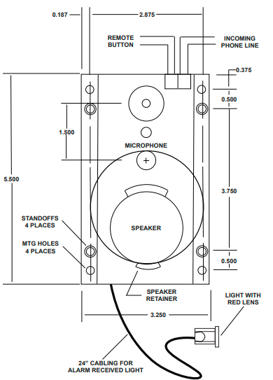
- Attach the red lens cap and bezel to the ¼” hole on the car station.
- Insert the LED into the lens cap and plug the wire into the white LED1 connector.
- Attach emergency button leads to the green connector at “BUT”.
- Attach the phone line to the green connector at “TEL” or the P1 (TELCO) modular phone jack if available.
G3 Phone Layout
P.C. Board Diagram 1
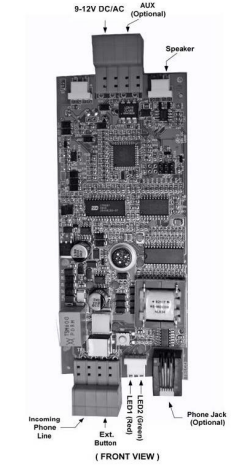
Diagram 2

P.C. Board Diagram 3
Programming Set-Up Methods
There are two methods for programming the JANUS ADA Telephone G3 Line Powered. Select the one applicable to your situation as described below.
- From any touch-tone phone, call the phone number to which the elevator phone is connected.
- After four rings (or if the “HELP” button is pressed), the JANUS ADA Telephone G3 Line Powered will turn on automatically, and you will hear a diddle-diddle-diddle sound.
- Go to the “Programming Instructions” section to continue. After programming the phone, you should test it by pressing the “HELP” button. The test will ensure the phone is functioning correctly and as programmed.
Using the Keypad on the Board to Program it.
- Connect a 9-volt battery to the battery clips on the board.
- Wait 30 seconds and then press the “PROGRAM” button above the keypad.
- Make sure that the red light of the JANUS ADA Telephone G3 Line Powered turns on. If it does not, go back to step 3 and start again.
- The elevator phone will turn on, and you will hear a diddle-diddle-diddle sound.
- Go to the “Programming Instructions” section.
- When you have completed the programming of the phone, you can unplug the 9-volt battery.
- After programming the phone, you should test it by pressing the “HELP” button.
- This test ensures the JANUS ADA Telephone G3 Line Powered is functioning correctly and as programmed.
Programming Instructions
- Choose programming setup method A or B.
- Enter # 94851 or # 9000000 to get into programming mode. Listen for three beeps.
- Enter # 0 (enter the first phone number to be programmed) * #. Listen for three beeps. EXAMPLE: # 0 5551212 * #.
- Enter # 1 (enter second phone number to be programmed) * #. (Optional)
- Enter # 2 (enter third phone number to be programmed) * #. (Optional)
- Enter # 3 (enter fourth phone number to be programmed) * #. (Optional)
- Enter # 7 and listen for the single beep. At the beep, record the location message by speaking into the touch-tone phone handset or into the microphone of the G3 phone when using the keypad to program.
- Enter 0 to end. If you want to listen to the location message without changing it, enter # 8.
- Enter # * 1180183 * # and listen for three beeps (enables voice prompt messages).
- Enter # # to hang up the phone.
Optional Programming Instructions
- Enter # 94851 or #9000000 and listen for three beeps.
- Enter # 0 * #, listen for three beeps, enter # 1 * #, listen for three beeps.
- Enter # 2 * #, listen for three beeps, enter # 3 * #, listen for three beeps.
- Enter # * 1180180 * #, listen for three beeps. (Optional)
- Enter # # and hang up.
To Disable the Voice Prompt Message
- Enter # 94851 or #9000000 and listen for three beeps.
- Enter # * 1180180 * #, listen for three beeps.
- Enter # # and hang up.
- Enter: # 94851 or #9000000 and listen for three beeps.
- Enter: # * 1180185 * # and listen for three beeps.
- Enter: # # and hang up.
PURPOSE: To enable Voice Prompt Message (DEFAULT): To enable the voice prompt message to say: “Elevator call, at the tone press one to talk, press two for location”.
- Enter # 94851 or #9000000 and listen for three beeps.
- Enter # * 1180183 * # and listen for three beeps.
- To program the location message, see programming instructions.
- Enter # # and hang up.
List of Commands for Programming Mode
- #0 First Phone Number *#
- #1 Second Phone Number *#
- #2 Third Phone Number *#
- #3 Fourth Phone Number *#
- #4 Identification Code *#
- #5 Programming New Password *# – Set Programming Access Code
- #7 – Records location message
- #8 – Plays back the location message
- #* 1 XXX Y W Z *# – setup code (Default is: #* 1 180 1 8 3 *#)
- XXX – Call Timer [000,060-990], 000=Disable timer
- Y – Push Button Control [0-2]
- [0] Push on = turn on/push again = play message
- [1] Push on = turn on/push again = turn off
- [2] Push and hold = turn on/release = turn off
- [3-8] Push and hold to turn on for Y amount of seconds to make a call. If pushed for less than Y amount of seconds, turn off/push again = turn off
- W – Unit ID [1-8]
- Z – Voice Mode [0,3 or 5]
- **42 X *# – Ring Count (for incoming calls) (0-9 range, 4 = default, 0 = no answer)
- **43 X *# – Ring Time (for outgoing calls) (18-60 range, 50 is default)
- **44 X *# – AUX1 behavior (0-2), 0 = disabled, 1 = red led, 2 = green led, 3 = VCC mode
- **45X*# – Redial, 0 = disabled (Default), 1 = Dial the number 1 more time, 2 = Dial the number 2 more times
- **8 XX *# – Set Language (1 = English: default, 2 = Spanish, X= [1-2] (must have 2 digits)
- **7 0 *# – Ring-Thru Converse Mode (Default). With this setting, the G3 will automatically enter two-way communication after it has answered an incoming call.
- **7 1 XXXX *# – Hang Up Converse Mode – Set Remote Access Code.
- ## – Exits programming mode
- **90 *# – Sets the following Default Values:
- #*1180183*# – Default Setup Code.
- **43 50 *# – Ring Time (for outgoing calls)
- **45 0*# – Disable Redial
Auxiliary Outputs Information
AUX/Relay (optional): The AUX output, by default, will not be active (open). If the user would like to activate this output, they must program code: **44X *# – which controls the AUX behavior. The letter X in this code could be substituted by 0, 1, 2, or 3.
- 0 = Disabled (default) – The AUX will stay OPEN.
- 1 = Red LED mode – The AUX will close when the red LED turns ON and open when the red LED turns “OFF”.
- 2 = Green LED mode – The AUX will close when the green LED turns ON and open when the green LED turns OFF”.
- 3 = VCC mode – The AUX will close when the phone turns ON and open when the phone turns “OFF”.
Specifications
The JANUS ADA Telephone G3 Line Powered comes with the following technical specifications to ensure proper installation and operation:
Input Connections: One shielded twisted pair communication cable (shield should be grounded at the controller only). Phone Line Requirements: Standard (Analog) loop start voice grade touch tone telephone line, PBX, or key system station analog telephone line.
- Size (H x W x D): 5.5in x 3.2in x 0.75in (140mm x 81mm x 19mm)
- Weight: 0.37lbs (0.17Kg)
- Optional AC Adapter: 9-12VDC/VAC @ min. 200mA
- Operating Current Range: 18mA to 55mA
- Phone Line Voltage: On-hook 24VDC to 70VDC (nominally 48VDC)
- Phone Line Voltage: Off-hook 8 to 20VDC (nominally 14VDC)
- Dialing: DTMF (Dual Tone Multi-Frequency)
- Frequency Response: 550Hz – 3400Hz +/- 3db.
- Operational Loop Impedance: 600 ohms
- Ring Sensitivity: 30 – 120VAC RMS
- FCC Registration: US: NLFTE07BG3X7771
- Ringer’s Equivalent Number: 0.7B
- Operating Temperature Range: 32 to 122°F (0 to 50 °C)
- Storage Temperature Range: -4 to 158°F (-20 to 70 °C)
- Relative Humidity: Up to 95% (non-condensing)
Troubleshooting Guide
When experiencing issues with the JANUS ADA Telephone G3 Line Powered, always visually check the phone for loose or shorted wires, physically damaged, or missing components. This phone will not work on a digital phone line and only functions properly on an analog phone line or an analog port from a digital phone system. Problem: Phone would not turn ʻONʼ
- Check the phone line connection.
- Check phone line voltage (normal C.O. line 48-52VDC or 20- 35VDC – internal systems)
- Try connecting a fully charged 9-Volt battery. ry
- Check if the unit is pulling down the line voltage (you should read the\ same as the phone line voltage)
- Check the voltage at the controller
- Check the button connection
- Check to see if the phone is on a ring-down line
- Check to see if another auto-dialer is on the line and remove it
- Reprogram unit
- Check speaker connection (see P.C. Board Diagram)
- Try calling into the unit and speaking to the person in the car
- Measure the resistance of the speaker, which should read approximately 40-45ohms
- Check the button connection
- Try a spare pair of wires through the traveling cable
- Check if the wire is running through the hoistway by itself
- Check if there is loud background noise in the cab
- Check the location of the microphone
- Check the mounting of the unit
- Hold the unit in hand and test
- Try adjusting the speaker and microphone volumes
- Check if other devices are on the line
- Check the voltage on the phone line
- Check polarity on the phone line
- Make sure the unit is off
- Remove the unit from the line to see if the line is still busy
- Check the phone line connection
- Check ring voltage (min. 30VRMS)
Warranty
Janus warrants its products to be free from defect in materials and workmanship under normal use and service for 24 months from the date of purchase. anus shall not be responsible for any damage to the unit incurred during installation. For warranty service, contact Janus.
Return Policy
If the technician determines that the product is not functioning, an RA (Return Authorization) number will be issued, allowing the installer to return the product for repair, replacement, or credit. Returns with no fault found will result in a bench charge plus shipping costs. Returns without an RA number will result in a restocking charge of 25% or more, plus shipping costs.
Customer Support
- Address: Janus Henderson 801 Pennsylvania JANUS Pana40Plus 2D-3D Detector Controller Ave, Suite 219109 Kansas City, MO 64105-1307
- Website: https://www.janushenderson.com
- Tel: 800-525-3713.
- Tomings: Weekdays, 9 a.m. – 6 p.m.
FAQs
Q: How does the Line Monitor Alert work?
The gadget keeps an eye on the phone line’s voltage all the time. The alarm indicator (LED or buzzer) turns on when the voltage falls below a certain threshold or the line is unplugged, and an external alert system may be triggered by a relay output.
Q: What does “LMA-NC” stand for?
“NC” stands for Normally Closed relay contacts, which means the relay circuit stays closed during regular operation and opens when a fault or line drop is detected. “LMA” stands for Line Monitor Alert.
Q: What is the input voltage range for monitoring?
Usually detecting line voltages between 24 and 52 volts DC, the device sounds a warning when the voltage falls much below the operational threshold (e.g., under 10 volts).
Q: What power supply does the unit require?
The LMA-NC uses very little current from the monitored line because it is a self-powered device. For increased usefulness, some versions might accept an external 12V or 24V DC input.
Q: How do I connect the relay output?
By default, the relay contacts are Normally Closed (NC). Connect the relay terminals to your external alarm system in accordance with its voltage and current requirements, which are typically 0.5A/125V AC or 1A/30V DC.
Q: How can I test the unit?
The LED and relay output should react within a few seconds when one side of the phone line is disconnected or a voltage drop is simulated, indicating normal functionality.
Q: Is it suitable for VoIP or digital lines?
No, analogue DC-based telephone lines are the intended use for the LMA-NC. On digital, fiber-optic, or VoIP-based lines without line voltage, it won’t work properly.