
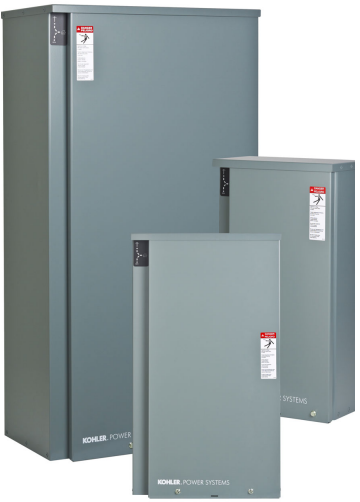
Kohler RXT Automatic Switch 100- 400 Amps User Manual

Codes and Standards
The ATS meets or exceeds the requirements of the following specifications
- Underwriters Laboratories UL 1008, Standard for Automatic Transfer Switches for Use in Emergency Systems, file #E58962
- Underwriters Laboratories UL 508, Standard for Industrial Control Equipment
- CSA certification available, file #LR58301 (not available for 150, 300, or 400 amp service entrance or 100 amp load center models). Must be selected when the transfer switch is ordered.
- NFPA 70, National Electrical Code
- NFPA 110, Emergency and Standby Power Systems
- NEMA Standard IC10- 1993, AC Automatic Transfer Switches
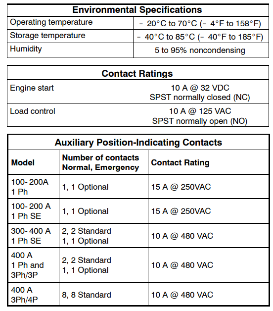
Specifications
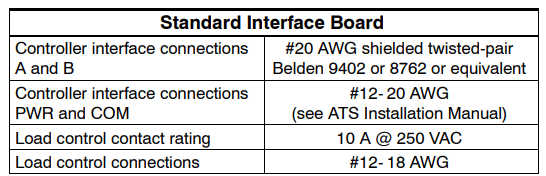
Optional Combined Interface/Load Management Board
The RXT transfer switch is available with either a standard interface board or a combined interface/load management board. The combined board allows load management as described below.
Load Management
- The combined load management board disconnects non-critical loads to prevent generator overload, in compliance with NEC.
- The combined load management board monitors generator current and frequency to determine when to add or shed loads. This monitoring prevents frequency drops that can damage valuable electronics like computers and televisions.
- Load management allows the use of a smaller generator set.
Operation
- Loads are automatically added or shed based on generator capacity.
- The load control system uses dynamic logic to prevent shedding important loads unnecessarily when air conditioning, refrigerator, or water pump motors start (patent pending).
- The load management board and generator communicate to provide smart power management. The time to shed loads decreases as each load is shed to quickly adapt to critical power requirements.
- Load shed power level and frequency setpoints can be adjusted using a personal computer (laptop) and Kohlerr SiteTech software, which is only available to Kohler-authorized distributors and dealers.
Priority Setting
- Loads are added and shed according to their priority. Load 1 is the top priority, which is added first and shed last. Load 6 is the lowest priority.
- Less critical loads can be turned off automatically when essential appliances are running.
- Load priorities are hard-wired at installation.
Viewing Load Shed Outputs with OnCuer Plus
- Use Kohler’s OnCuer Plus Generator Management System (sold separately) to view load status (On or Off) for loads connected to the load shed relays.
- Use OnCuer Plus to remotely monitor when loads are shed or added.
- The load shed outputs can be labeled in OnCuer Plus.
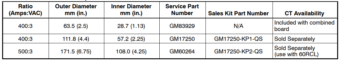
Current Transformer
- The combined load management board option includes a 400-amp current transformer (CT) for load monitoring.
- A larger diameter CT is available for applications that require larger cables.
- A 500-amp CT is available for use with a 60RCL generator.
- See the table below for current transformer specifications and optional kit numbers.
Load Shed Specifications
Current Transformer Specifications
Service Entrance Transfer Switch Ratings
The service entrance transfer switch is factory-equipped with a normal source disconnect circuit breaker. Suitable for the control of motors, electric discharge lamps, tungsten filament lamps, and electric heating equipment where the sum of motor full-load ampere ratings and the ampere ratings of other loads does not exceed the ampere rating of the switch, and the tungsten load does not exceed 30 percent of the switch rating.g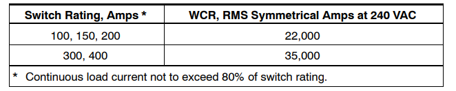
Contactor Ratings with Coordinated Circuit Breakers
The following table lists contactor withstand current ratings (WCR) for 100- 400 ampere non-service entrance rated switches with specific manufacturer’s circuit breakers per UL and Canadian safety standards.
Suitable for the control of motors, electric discharge lamps, tungsten filament lamps, and electric heating equipment where the sum of motor full-load ampere ratings and the ampere ratings of other loads does not exceed the ampere rating of the switch, and the tungsten load does not exceed 30 percent of the switch rating.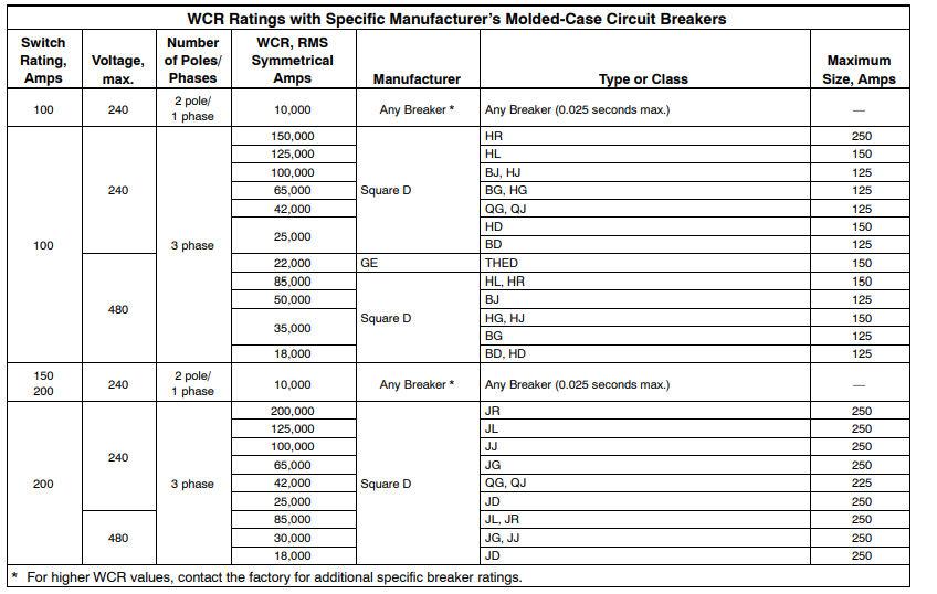
WCR Ratings with Specific Manufacturer’s Molded-Case Circuit Breakers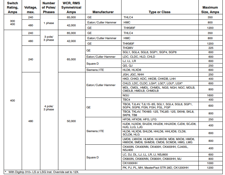
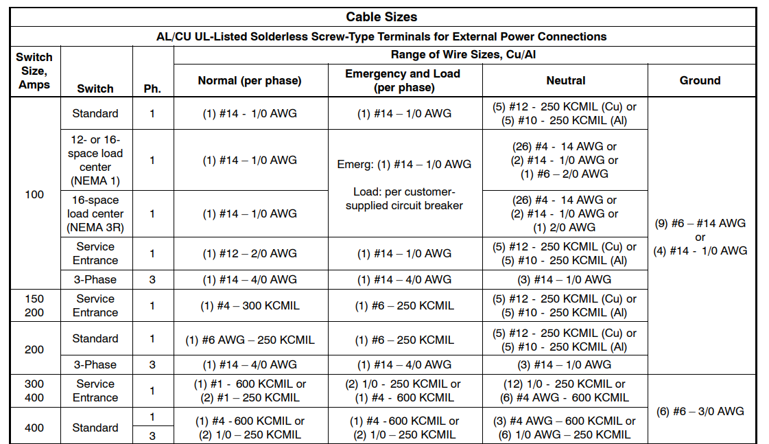
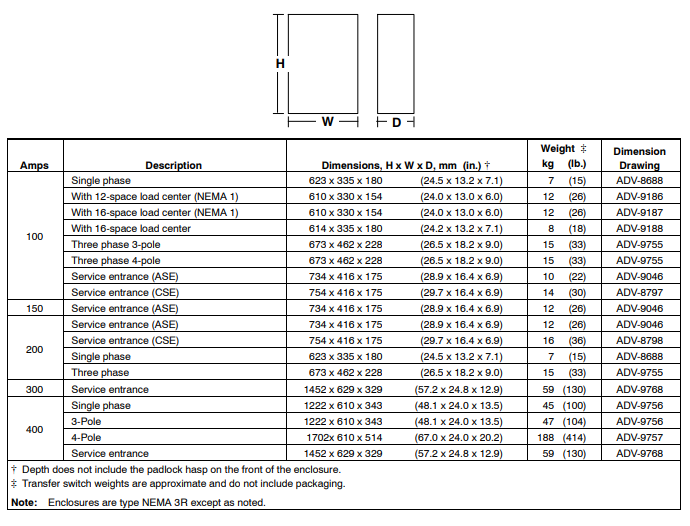
Dimensions and Weights
Always use the transfer switch dimension drawing for planning and installation. Weights and dimensions may vary for different configurations. See the Operation/Installation Manual or your local distributor for dimension drawings.
Accessories
Auxiliary position-indicating contacts
- Standard on 300- 400 amp models, optional for others
- One closed in the normal position and one closed in the emergency position
- Form C contacts rated 15 A @ 250 VAC
Power relay modules
- 50 amp DPST power relay mounted in a NEMA type 3R enclosure
- Use up to four modules with the combined interface/load management board
- UL/cUL listed
- Dimensions: 172 x 233 x 92 mm (6.8 x 9.2 x 3.6 in.)
- For more information, see specification sheet G6-143
Status indicator kit for standard interface board
- LEDs indicate normal and emergency source availability and contactor position.
- Mounts on the outside of the RXT enclosure
- View transfer switch status without removing the enclosure cover
- An overhang on the enclosure protects the indicator panel and ribbon cable opening
- Dimensions: 92 mm x 42 mm (3.62 in. x 1.65 in.)
- Connects to the standard interface board only
- Not available for the 400 amp/4 pole model
- For more information on the status indicator kit, see specification sheet G11-123.
Status indicator kit for combined interface/load management board
- LEDs indicate normal and emergency source availability and contactor position
- Dual color LEDs for each load indicate load status (powered or shed) and flash during a test
- The load shed test button allows the operator to cycle the load shed relays in order of priority (when the generator is in RUN mode)
- Mounts on the outside of the RXT enclosure
- View transfer switch and load status without removing the enclosure cover
- An overhang on the enclosure protects the indicator panel and ribbon cable opening
- Dimensions: 183 mm x 42 mm (7.20 in. x 1.65 in.)
- Connects to the combined interface/load management board only
- Not available for the 400 amp/4 pole model
- For more information the see
specification sheet G11-123
Auxiliary circuit breaker (service entrance models only)
- Single-pole type QO circuit breaker
- Mounts on a bracket inside the enclosure
- 15-amp and 20-amp circuit breakers Kohler RXT Automatic Switch 100- 400 Amps are available
Available Models
All Model RXT transfer switches are standard-transition 60 Hz automatic transfer switches. Letters in parentheses refer to the model designation code described on the last page.
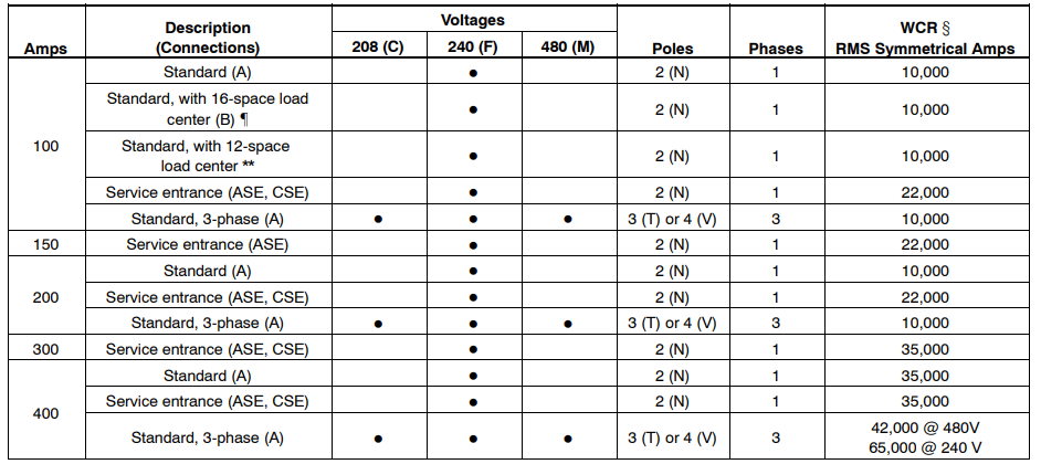
Withstand and close-on rating. See pages 3-5 for WCR information and specific breaker ratings. With a 16-space load center and NEMA 1 or NEMA 3R enclosure. Up to 8 tandem breakers can be used for a maximum of 24 circuits. GM85273- SA_ with 12-space load center and NEMA 1 enclosure.
Model Designation
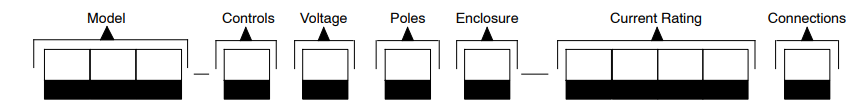
Record the transfer switch model Kohler RXT Automatic Switch 100- 400 Amps designation in the boxes. The transfer switch model designation defines ratings and characteristics as explained below.
Sample Model Designation
Model
- RXT: Kohler Automatic Transfer Kohler RXT Automatic Switch 100- 400 Amps Switch Controls J: Interface for RDC2 Controller (standard or combined interface/ load management) Voltage/Frequency C: 208 Volts/60 Hz (3-phase only)
- F: 240 Volts/60 Hz M: 480 Volts/60 Hz (3-phase only) Number of Poles/Wires N: 2-pole, 3-wire, solid neutral (120/240 V only) T: 3-pole, 4-wire, solid neutral V: 4-pole, 4-wire, switched neutral
Enclosure
- A: NEMA 1 * C: NEMA 3R * NEMA 1 enclosure is available on 100 amp load center models only. Current Rating Connections A: No load center B: With load center (100 amp single-phase only)
- ASE: Service entrance rated CSE: Service entrance rated with CSA certification (not available for 150 amp models) 0100: 100 amps 0150: 150 amps 0200: 200 amps 0300: 300 amps 0400: 400 amps
Customer Support
- Tel: 1-800-456-4537
- Website: www.kohler.com
- Visit: www.kohler.ca
- Timings: 8:00 AM – 5:00 PM
FAQs
What current ratings are available for the RXT Automatic Switch?
In order to satisfy different load requirements in residential, commercial, or industrial environments, the switch supports variants with capacities ranging from 100 amps to 400 amps.
How do I select the correct RXT model for my application?
Choose the type according to the highest continuous current load that your system can handle, making sure that the switch rating is higher than the electrical panel’s peak load to avoid overload.
What types of power sources are compatible with the RXT Automatic Switch?
The switch works with standby generators, such as those that run on natural gas, propane, or diesel, as well as utility electricity.
Can the RXT Automatic Switch be manually overridden?
Indeed, there is a manual override capability on the switch that lets you manually switch power sources in an emergency or for maintenance.
What safety features are included?
To protect the equipment and related electrical loads, the switch has built-in overload protection, short circuit detection, and automatic fault reset.