


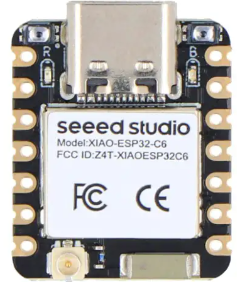
Seeed Studio BM3301–1313 BLE 5.4 Wireless Module
Introduction
The Seeed Studio BM3301–1313 BLE 5.4 Wireless Module is a high-performance 2.4GHz Wi-Fi6 and Bluetooth Low Energy module based on TI’s 10th connectivity combo chip CC3301, which is proven technology. This module is ideal for cost-sensitive embedded applications with a Linux or RTOS host running TCP/IP. It provides a solid platform for developing wireless communication product solutions. For similar IoT and embedded projects, you can also check the Seeed Studio XIAO ESP32S3 Series guide.
Features
The Seeed Studio BM3301–1313 BLE 5.4 Wireless Module comes with advanced features for Wi-Fi 6 and Bluetooth Low Energy connectivity.
Then keep the bullet points exactly as they are:
Wi-Fi 6
- 2.4 GHz, 20 MHz, single spatial stream
- MAC, baseband, and RF transceiver with support for IEEE 802.11 b/g/n/ax
- Target wake time (TWT), OFDMA, MU-MIMO (Downlink), Basic Service Set Coloring, and trigger frame for
improved efficiency
- Hardware-based encryption and decryption using supporting WPA2 and WPA3
- Excellent interoperability
- Support for 4-bit SDIO or SPI host interfaces
Bluetooth Low Energy
- LE Coded PHYs (Long Range), LE 2M PHY (High Speed), and Advertising Extension
- Host controller interface (HCI) transport with option for UART or shared SDIO
- Security
- Secured host interface
- Firmware authentication
- Anti-rollback protection
- Application throughput up to 50 Mbps
- 1 integrated antenna port (supporting Wi-Fi and Bluetooth Low Energy coexistence)
- Compact footprint and pins with an SMT package
- Integrated 2.4-GHz PA for a complete wireless solution with up to +20dBm output power
- Using an IPEX Gen4 socket to connect an external antenna (ex, Rubber ducky antenna, PCB antenna, FPC antenna)
- Operation temperature: -40℃ to 85℃
- Operation humidity: 10%~ 85%
Application
- Internet of Things (IoT)
- Multimedia
- Home Electronics
- Home Application and White Goods
- Industrial and Home Automation
- Smart Gateway and Metering
- Video Conferencing
- Video Camera and Security
This product specification includes a detailed description of the BM3301 – 1216 Module’s performance and functions. For the latest firmware, product updates, or errata, please contact Seeed Studio. dio
Description
BM3301 – 1216 Module is embedded with TI CC3301, which is very suitable for the design of various embedded devices. The module, as seen in the diagram below, comprises: – 40MHz XTAL.
- Bandpass filter
- Decoupling capacitors
- IPEX Gen 4 connector (BM3301-1216)
Pin Diagram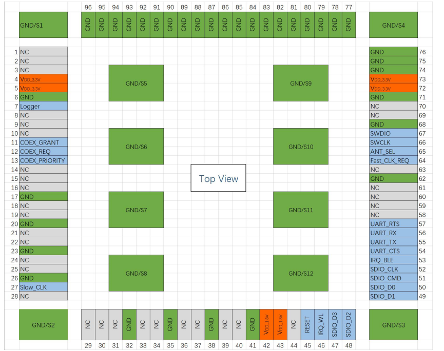
Pin Attributes
| Number | Name | Voltage Level | Type | Description | ||
| 1 | VDD_3.3V | 3.3V | Power | 3.3V Power Supply |
| 2 | VDD_3.3V | 3.3V | Power | 3.3V Power Supply |
| 3 | GND | – | Ground | |
| 4 | Logger | 1.8V | O | UART TX Debug Logger (Reuse as working mode configuration |
| 5 | ||||
| 9 | ||||
| 6 | NC | – | Not connected | |
| 7 | COEX_GRANT | 1.8V | O | External Coexistence Interface -Grant |
| 8 | COEX_REQ | 1.8V | I | External Coexistence Interface -Request |
| 9 | COEX_PRIORITY | 1.8V | I | External Coexistence Interface -Priority |
| 10 | NC | – | Not connected | |
| 11 | NC | – | Not connected | |
| 12 | NC | – | Not connected | |
| 13 | GND | – | Ground | |
| 14 | NC | – | Not connected | |
| 15 | NC | – | Not connected | |
| 16 | GND | – | Ground | |
| 17 | NC | – | Not connected | |
| 18 | NC | – | Not connected | |
| 19 | GND | – | Ground | |
| 20 | NC | – | Not connected | |
| 21 | NC | – | Not connected | |
| 22 | GND | – | Ground | |
| 23 | Slow_CLK | 1.8V | I | External Slow Clock Input |
| 24 | NC | – | Not connected | |
| 25 | NC | – | Not connected | |
| 26 | NC | – | Not connected | |
| 27 | NC | – | Not connected | |
| 28 | GND | – | Ground | |
| 29 | NC | – | Not connected | |
| 30 | NC | – | Not connected | |
| 31 | GND | – | Ground | |
| 32 | GND | – | Ground | |
| 33 | GND | – | Ground | |
Electrical characteristics
Absolute Maximum Ratings
Reaching or exceeding the maximum ratings listed in the table below can cause equipment damage.
| Parameter | Description | min | max | unit |
| VDD_3.3V | 1216-Module 3.3V Supply Voltage | -0.5 | 4.2 | V |
| VIO/1V8 | 1216-Module IO Voltage | -0.5 | 2.1 | V |
Normal working conditions
| Parameter | Description | min | TYP | max | unit |
| VDD_3.3V | 1216-Module 3.3V Supply Voltage | 3.0 | 3.3 | 3.6 | V |
| VIO | 1216-Module IO voltage | 1.62 | 1.8 | 1.98 | V |
| Top | Operation temperature | -40 | +85 | ℃ |
Electrical Characteristics
| Parameter | Description | Test Condition | min | TYP | max | unit |
| VIH | High-level input voltage | 0.65 x VIO | VIO | V | ||
| VIL | Low-level input voltage | 0 | 0.35 x VIO | V | ||
| VOH | High-level output voltage | At 4mA | VIO – 0.45 | VIO | V | |
| VOL | Low-level output voltage | At 4mA | 0 | 0.45 | V |
Module specifications
| ITEMs | Parameter | Specifications | Unit | ||||||||
| Structure | Size | 1216-Module | 12(W) x 16(L) x 2.1(H)Max | ||||||||
| Package | 1216-Module | 108 pins LGA Module | |||||||||
| Sleep current | 1216-Module | 215(TBD) | |||||||||
| Operation current
(Transmitter) |
1216-Moudle | 3.3V | 360 | 470 | 20.2dBm 6 OFDM | mA | |||||
| 65 | 305 | 20dBm BLE 1M Channel 4 | |||||||||
| Operation current | TBD @ Wi-Fi Continuouss Receive | mA | |||||||||
| (Receiver) | TBD @ Bluetooth Scan | ||||||||||
| TBD @ Wi-Fi Scan | |||||||||||
| TX Output power(Max) | 20 @ 11ax SU ER MCS0 | dBm | |||||||||
| 16 @ BLE 20dBm 1M Channel 4 | |||||||||||
| Sensitivity | Wi-Fi@20-MHz bandwidth. At <10% PER limit | dBm | |||||||||
| Conditi ons | min | type | max | ||||||||
| 1 DSS | – | – | |||||||||
| 2 DSS | – | – | |||||||||
| ITEMs | Descriptions | ||||||||||
| Peripheral
Interface |
SDIO 3.0 | ||||||||||
| SPI | |||||||||||
| UART | |||||||||||
| Coexistence | |||||||||||
| SWD | |||||||||||
Timing and Switching Characteristics
Power Supply Sequencing
For proper operation of the device, perform the recommended power-up sequencing as follows:
- All supplies (VBAT, VIO) must be available before Reset is released. 2. For an external slow clock, ensure that the clock is stable before Reset is deasserted (high). 3. The Reset pin should be held low for 10 us after stabilization of the external power supplies
Slow Clock Generated Internally
In order to minimize external components, the slow clock can be generated by an internal oscillator. However, this clock is less accurate and consumes more power than sourcing the slow clock externally. For this scenario, the Slow_CLK pin should be left unconnected.
Slow Clock Using an External Oscillator
For optimal power consumption, the slow clock can be generated externally by an oscillator sourced from elsewhere in the system. The external source must meet the requirements listed below. The is
Clock should be fed into the BMCC3301-1313 pin Slow_CLK and should be stable before nReset is deasserted and he device is enabled.
| Parameter | Description | min | TYP | max | Unit |
| Input slow clock frequency | Square wave | 32768 | Hz | ||
| Frequency accuracy | Inital + temperature + aging | ±250 | ppm | ||
| Input Duty Cycle | 30 | 50 | 70 | % | |
| Rise and fall time | 10% to 90% (rise) and 90% to 10% (fall) of the digital signal level | 100 | ns | ||
| VIL (Input low level) | 0 | 0.35 x VIO | V | ||
| VIH (Input high level) | 0.65 x VIO | 1.95 | V | ||
| Input impedance | 1 | MΩ | |||
| Input capacitance | 5 | pF |
Application Information
Package information
M3301-1216 Module Package information
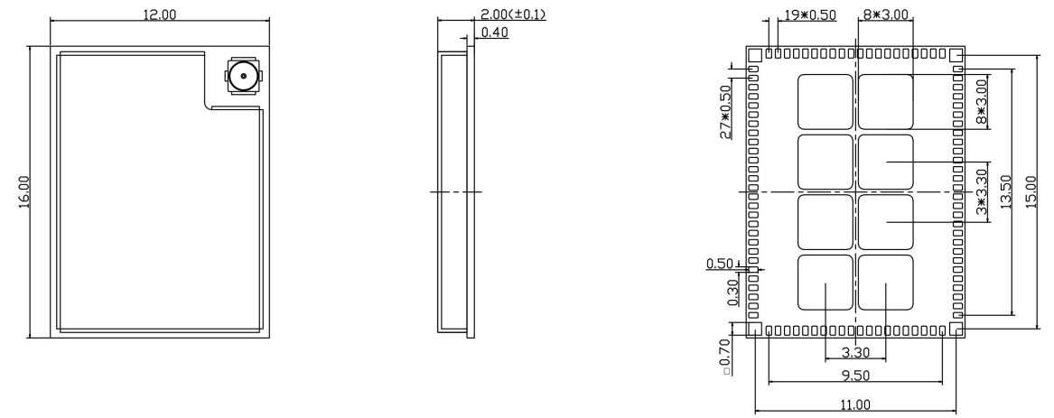
Land Pattern
The following figure shows the recommended pad dimensions
Reference design based on BM3301-1216 Module
Considering different application scenarios, we provide two different reference designs.
BM3301-1216 Module Block Diagram SDIO Iines
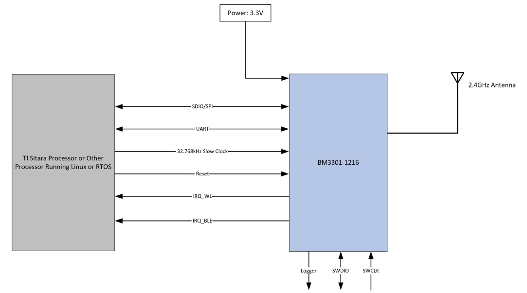
Due to the size of the module, the length of the SDIO lines is not equal within the module, and it is necessary to compensate for the unequal lengths lines in your design.
The length of each SDIO line of the M3301-1216 Module
- SDIO_CLK: 539.16 mil
- SDIO_CMD: 570.29 mil
- SDIO_D0: 481.10 mil
- SDIO_D1: 502.99 mil
- SDIO_D2: 506.48 mil
- SDIO_D3: 502.13 mi
Ordering Information
| Part Number | Package size (mm) | IPEX GEN4 |
| BM3301-1216 Module | 12(W) x 16(L) x 2.1(H) max | Yes |
Reversion
FCC
This device complies with part 15 of the FCC Rules. Operation is subject to the following two
conditions:
- This device may not cause harmful interference, and
- This device must accept any interference received, including interference that may cause undesired operation
Thimodulear complies with FCC RF radiation exposure limits set forth for an uncontrolled environment.
The module is limited to OEM installation ONLY. The OEM integrator is responsible for ensuring that the end-user has no manual instructioremove ormoveor install the module.
IC
This device contains licence-exempt transmitter(s)/receiver(s) that comply with Innovation, Science and Economic Development Canada’s licence-exempt RSS(s). Operation is subject to the following two conditions:
- This device may not cause interference. (2)This device must accept any interference, including interference that may cause undesired operation of the device. L’émetteur/récepteur exempt de licence contenu dans le présent appareil est conforme aux CNR d’Innovation, Sciences et Développement économique Canada applicables aux appareils radio exempts de licence. L’exploitation est autorisée aux deux conditions suivantes :
- ‘appareil ne doit pas produire de brouillage;
- L’appareil doit accepter tout brouillage radioélectrique subi, même si le brouillage est susceptible d’en compromettre le fonctionnement. This transmitter must not be co-located or operating in conjunction with any other antenna or transmitter.
- Et l’émetteur ne doit pas être colocalisé ou fonctionner en conjonction avec une autre antenne ou un autre émetteur.
This exterior label can use wording such as the following: “Contains IC: 21046-BM33011216. Any simwording similar to expresses the same meaning may be used. Veuillez noter que si le numéro de certification ISDE n’est pas visible lorsque le module est installé à l’intérieur d’un autre dispositif, alors l’extérieur du dispositif dans lequel le module est installé doit également afficher une étiquette référant au module fermé. Cette étiquette extérieure peut utiliser des libellés tels que «:concontientICIC:21046-BM33011216».Toute formulation similaire qui exprime la même signification peut être utilisée.
| Antenna Type | Antenna Gain |
| Rod antenna | 2.81 dBi |
| PCB antenna | 2.87 dBi |
Trace antenna designs: Not applicable.
| Type d’antenne | Max Gain d’antenne |
| Rod antenna | 2.81 dBi |
| PCB antenna | 2.87 dBi |
Customer Support
- Website: www.seeedstudio.com
- Ph: +86-0755-86095676
2008-2025 Seeed Technology Co., Ltd. All rights reserved.