


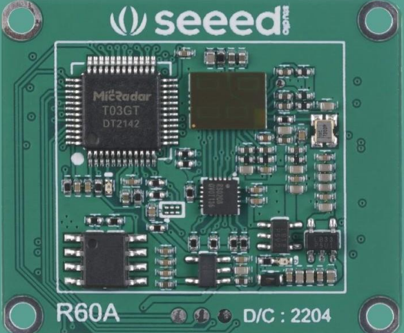
 Seeed Studio MR60FDA1 Fall Detection Pro Module
Introduction
- The Seeed Studio MR60FDA1 Fall Detection Pro Module follows hardware circuit reference design, radar antenna, and housing layout requirements, helping distinguish interference and supporting multi-functional standard UART protocol output.
- The MR60FDA1 Fall Detection Pro Module is a self-contained space sensing sensor consisting of an RF antenna, radar chip, and high-speed MCU.
- The radar is a self-contained sensor with a combination of an RF antenna, a radar chip, and a high-speed main frequency MCU.
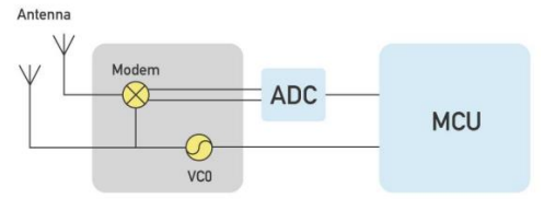
Working Principle
For users who also need heartbeat monitoring capabilities, see the Seeed Studio MR60BHA1 Heartbeat Detection Sensor User Guide for a detailed setup and operating instructions.
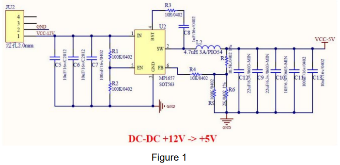
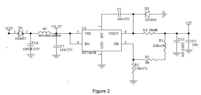
Hardware Design Considerations
The rated supply voltage of the radar needs to meet 4.9 – 6V, and the rated current needs to be 200mA or more. Input is required. The power supply is designed to have a ripple of ≤ 100mv.
Power supply can refer to the following circuit design

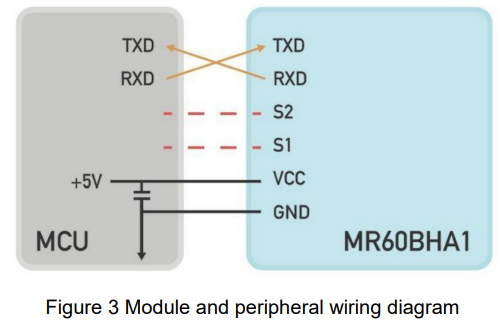
 Wiring Diagram
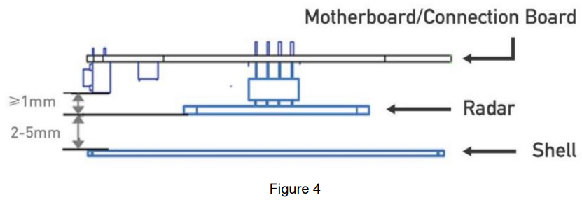
Antenna and housing layout requirements
- PCBA: Need to keep the radar patch height ≥ 1mm higher than other devices.. Housing structure: need to keep the radar antenna surface and the housing surface at a distance of 2 – 5mm distance
- Housing detection surface: non-metallic housing, needs to be straight to avoid bending surface affecting the performance of the whole sweep surface area.
Electrostatic protection
Radar products, such as the Seeed Studio MR60FDA1 Fall Detection Pro Module, have electrostatic-sensitive circuitry inside and are vulnerable to electrostatic hazards. Therefore, they need to be carefully handled during transport, storage, work, and other handling processes to ensure proper electrostatic protection.
It is essential to follow strict precautions when dealing with the MR60FDA1 Fall Detection Pro Module. Do not touch or grab the radar module antenna surface and connector pins; only handle the corners. When handling the radar sensor, wearing anti-static gloves is strongly recommended to prevent damage.
Function Description
| Function | Status change time/function explanation |
| DP1: occupied/unoccupied | From unoccupied to occupied, report within 0.5s From occupied to unoccupied, report within 30 s |
| DP2: Fall Alarm | Instantly report when fall alarm conditions are met |
| DP3: Stationary residence alarm | Abnormal hold stationary for 5 minutes, alarm |
Protocol Description
- Interface level: TTL
- Baud rate: 115200bps
- Stop bit: 1
- Data bits: 8
- Parity check: None
Communication ,,comma,,nd and parameter definition
- Frame structure definition and description
- Definition of frame structure
| Frame header | Control word | Command word | Length identifier | Data | Checksum | End of frame | |
| 0x53 0x59 | Control | Command | Lenth_H | Lenth_L | Data | Sum | 0x54 0x43 |
| 2 Byte | 1 Byte | 1 Byte | 1 Byte | 1 Byte | n Byte | 1 Byte | 2 Byte |
Description of the frame structure
- Frame header: 2 Byte, fixed to 0x53,0x59;
- Control word: 1 Byte
- (0x01 – heartbeat packet identification, 0x02 – product information, 0x03 – OTA upgrade, 0x05 – operation status, 0x07 – radar detection range information, 0x80 – human presence, 0x81 – breath detection, 0x84 – sleep monitoring, 0x85 – heart rate monitoring)
- Command word: 1 Byte (to identify the current data content)
- Length identification: 2 bytes, equal to the specific byte length of the data
- Data: n Byte, defined according to the actual function
- Checksum: 1 Byte. (Calculation method of checksum: “frame header + control word + command word + length identifier + data” summed to the lower eight bits)
- End of frame: 2Byte, fixed to 0X54,0X43;
Address Assignment and Data Information
| Function Category | Function Description | Transfer direction | Frame header | Control word | Command word | Length
Identification |
Data | Checksum field | End of frame | Note | |
| System Functions | Heartbeat Pack Report | Report | 0x53 0x59 | 0x01 | 0x01 | 0x00 | 0x01 | 0x0F | sum | 0x54 0x43 | Report per minute |
| Module Reset | Send | 0x53 0x59 | 0x01 | 0x02 | 0x00 | 0x01 | 0x0F | sum | 0x54 0x43 | ||
| Response | 0x53 0x59 | 0x01 | 0x02 | 0x00 | 0x01 | 0x0F | sum | 0x54 0x43 | |||
About the calculation of the check digit
Let’s take the command to send a human presence information query as an example. The data construction for the presence information query, confirmed by the protocol table above, is
- Frame header: 0x53 0x59
- Control word: 0x80
- Command word: 0x81
- Length identifier: 0x00 0x01
- Data: 0x0F
- Checksum: 1Byte (SUM)
- End of frame: 0x54 0x43
Combined into a complete instruction as follows
- 53 59 80 81 00 01 0F sum 54 43
- Check digit sum : 0x53 + 0x59 + 0x80 + 0x81 + 0x01 + 0x0F (0x53 + 0x59 + 0x80 + 0x81 + 0x00 + 0x01 + 0x0F) = 0x01BD
- The lower byte is sum = 0xBD
So the complete existence information query instruction is: 53 59 80 81 00 01 0F BD 54
Customer Support
- Website: www.seeedstudio.com
- Ph: +86-0755-86095676
3 Comments
Pingback: Seeed Studio MT7688 BG96 Module Setup & IoT Guide
Pingback: Seeed Studio MR24HPC1 Human Static Presence Module
Pingback: Seeed Studio MR60BHA1 Heartbeat Detection Sensor User Guide