

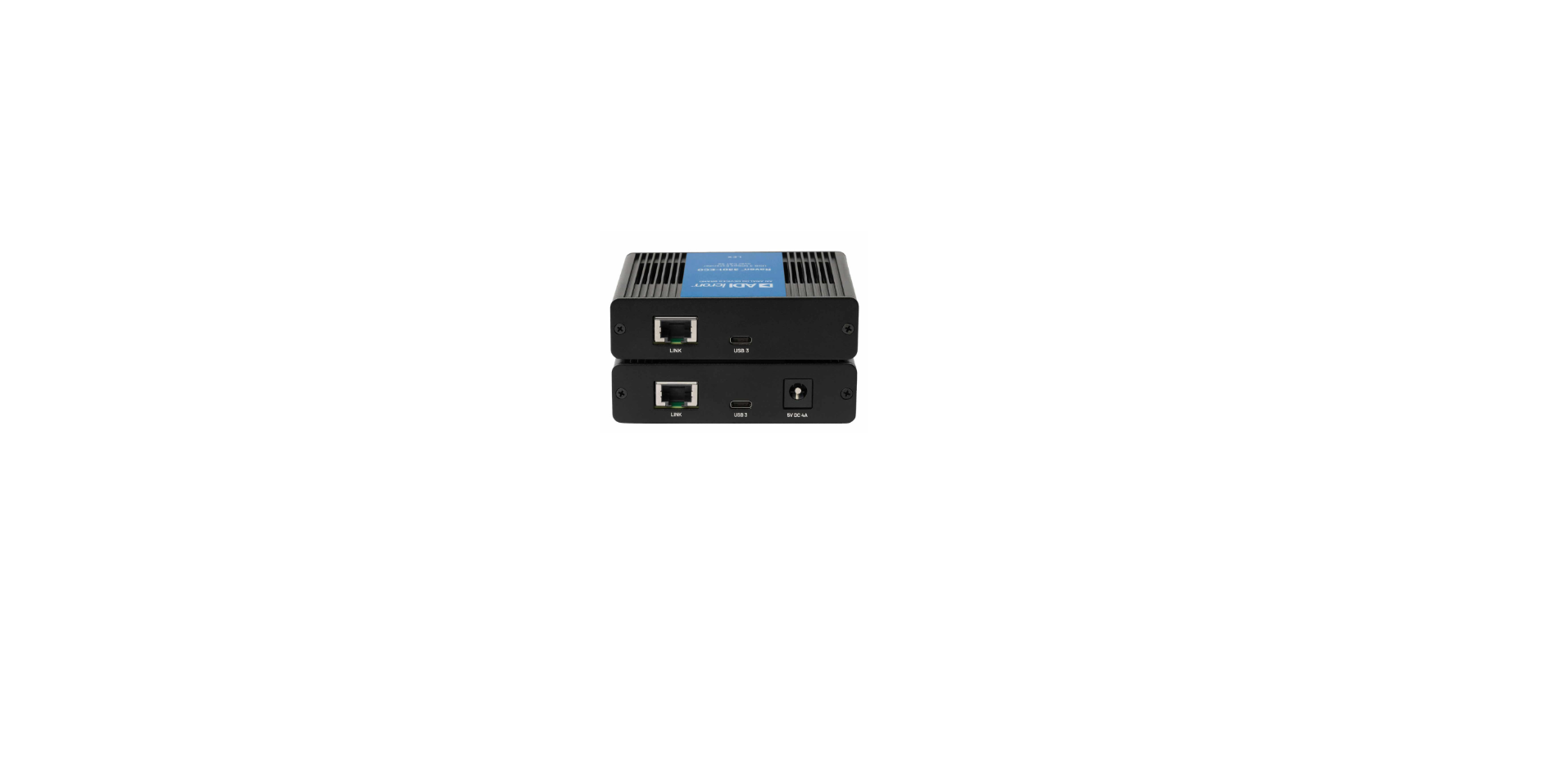

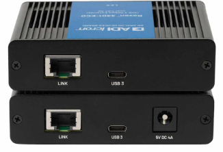
Icron Raven 3301-ECO Extender System
Introduction
This guide provides product information for the Raven 3301-ECO, installation instructions, and troubleshooting guidelines. The instructions in this guide assume a general knowledge of computer installation procedures, familiarity with cabling requirements, and some understanding of USB devices.
Product Contents
Your Raven 3301-ECO extender system contains:
- Raven 3301-ECO LEX (Local Extender)
- Raven 3301-ECO REX (Remote Extender)
- 5V DC 4A Power Adapter
- 1x Country Specific Power Cord
- Warranty and Compliance Insert
Features
The Raven 3301-ECO incorporates ExtremeUSB® technology, enabling users to extend USB 3 beyond the standard 3m cable limit for USB 3 peripheral devices.
- Extends USB 3 5Gbps up to 100m over a single CAT 5e cable
- Support for all USB 4 and older Gen 1/2 host controllers and devices (up to 5Gbps)
- Supports all USB transaction types (Control, Interrupt, Bulk, and Isochronous)
- The REX (remote extender) can power a single USB device up to 15W (5V 3A)
- Compatible with all major Unified Communications conferencing applications
The Raven 3301-ECO includes the ExtremeUSB® suite of features.
- Transparent USB extension
- True plug and play; no software drivers required
- Works with all major operating systems; Windows®, macOS™, Linux® and ChromeOS™
Quick Start Guide
Before you get started, ensure that all the drivers required for your USB device(s) are installed.
- Place extenders where desired and connect the CAT 5e extension link cabling to the Link ports (RJ45) on the LEX and REX.

- Connect the LEX to the computer using a USB 3.0 cable with a USB-C connector on one side, or both, depending on your port configuration.

- Connect the REX to the AC adapter and plug it into a power source.

- Attach the USB device(s) to the REX.

The LEX Unit
The LEX (Local Extender) is powered by the USB connection to the host computer and uses a standard USB-C cable (not included).

| Item | Type | Description |
| 1 | Config | Reserved for manufacturer use. |
| 2 | Mode | Reserved for manufacturer use. |
| 3 | Status LED | LED is SOLID ON whether the system is functioning normally. LED BLINKS when the system is booting or to indicate a temperature warning in unison with the LINK, USB 2, and USB 3 LEDs. |
| 4 | Link LED | LED is OFF when there is no connection between the LEX and REX units. |
| 5 | USB 2 LED | LED is SOLID ON when an active USB 2 connection is established through the extender system. |
| 6 | USB 3 LED | LED is SOLID ON when an active USB 3 connection is established through the extender system. |
| 7 | Link Port (RJ45) | Accepts RJ45 connector for CAT 5e cabling to connect the LEX to the REX. |
| 8 | USB Host Port | USB-C receptacle used to connect LEX to the USB 3 host computer. |
The REX Unit
The (REX) Remote Extender unit provides a single USB-C receptacle for standard USB devices up to 5Gbps. Up to 31 devices may be connected by attaching USB hubs to the REX. Powered by an external 5V DC 4A adapter, the REX supplies 3A at the USB-C port.

| Item | Type | Description |
| 1 | Config | Reserved for manufacturer use. |
| 2 | Mode | Reserved for manufacturer use. |
| 3 | Status LED | LED is SOLID ON when the system is functioning normally. LED BLINKS when the system is booting or to indicate a temperature warning in unison with the LINK, USB 2, and USB 3 LEDs. |
| 4 | Link LED | LED is SOLID ON when REX is linked to an opposite LEX. |
| 5 | USB 2 LED | LED is SOLID ON when an active USB 2 connection is established through the extender system. |
| 6 | USB 3 LED | LED is SOLID ON when an active USB 3 connection is established through the extender system. |
| 7 | Link Port (RJ45) | Accepts RJ45 connector for CAT 5e cabling to connect the REX to the LEX |
| 8 | Device Port (USB-C) | Accepts all USB devices. |
| 9 | DC Power Port | Connector for the included power adapter — accepts 5V DC 4A |
Installation Guide
Raven 3301-ECO Category Cabling Guidelines
When installing this product, it is appropriate to use Unshielded (UTP) cabling if the cable run installation meets the following requirements:
- The cable is not bundled with other cables
- The cable is not looped or coiled
- The cable is bundled with other cables
- The cable is rutightlyht against other Category cables
- The cable is placed near sources of interference, like power lines and radios
Raven 3301-ECO
Requirements
- USB-compatible computer (host computer) with a USB-compliant operating system
- USB compatible device(s)
- CAT 5e cabling with two information outlets and two CAT 5e patch cords with RJ45 connectors (if using premise cabling), ensuring the total cable length does not exceed 100m
Preparing

Before installing this system, you will need to prepare your site:
- Position your computer in the desired location and complete the setup.
- Ensure to locate your USB device(s) within a 100m range of your CAT 5e cable. If not, adjust the location of your device(s) and/or computer accordingly.
LEX Unit
- Place the LEX unit near the computer.
- Connect a USB-C cable between the LEX host port and a USB port on your host computer.
REX Unit
- Place the REX near the USB device(s).
- Assemble the 5V 4A power adapter and country-specific power cord together and connect them to a suitable AC outlet.
- Connect the power adapter to the REX.
Connecting the LEX to the REX
With Surface Cabling:
- Plug one end of the CAT 5e cable (not included) into the Link port (outermost RJ45 connector) on the LEX.
- Plug the other end of the CAT 5e cable into the Link port (outermost RJ45 connector) on the REX.

With Premise Cabling:
- Plug one end of a CAT 5e patch cord (not included) into the Link port (RJ45 connector) on the LEX.
- Plug the other end of the patch cord into the CAT 5e information outlet near the host computer.
- Plug one end of the second CAT 5e patch cord (not included) into the Link port (RJ45 connector) on the REX.
- Plug the other end of the patch cord into the CAT 5e information outlet near the USB device.
Checking the Installation
- On the LEX and REX units, check that the Status, Link, USB 2, and USB 3 LEDs are on.
Connecting a USB Device
- Install any software required to operate your USB device(s). Refer to the documentation for the USB device(s), as required.
- Connect the USB device to the device port on the REX.
Compatibility
The Raven 3301-ECO complies with USB 2.0 and USB 3 5Gbps specifications governing the design of USB devices. However, there is no guarantee that all USB devices or hosts will be compatible, as there are a number of different characteristics that may impact the operation of USB devices over extended distances.
USB Extender Mounting
The bottom of the Raven 3301-ECO enclosure features four convenient pre-drilled holes for optional mounting. Based on your requirements, choose from two available mounting options:
- USB Extender Mounting Kit (purchased separately)Order Part #10-00536 USB Mounting Kit – Black
- USB Extender Direct Surface Mounting (Use your own hardware and follow instructions listed on the next page)
USB Extender Mounting Kit
Each kit includes:
- 2 mounting brackets
- 4 (M2.5x8mm) Philips raised cheese head screws with split locking washers
- Mounting bracket installation guide
Use a Phillips screwdriver to fasten and secure the mounting bracket into place using the provided screws as illustrated. For mounting onto a surface. NOTE: You will need to provide your own screws to secure the extender onto the desired surface using the available slots on each bracket.

USB Extender Direct Surface Mounting
The bottom of the Raven enclosure features four pre-drilled Icron Raven 3301-ECO Extender System holes for optional surface mounting.

Distance between the enclosure mounting holes: 42.0mm x 88.5mm
- Mark the centre point of each of the four holes on your mounting surface either by directly measuring or printing the full-size stencil found in the Appendix on page 21.
- Hardware recommendation: M2.5 locking washers, Icron Raven 3301-ECO Extender System,m and M2.5 screws (4 of each per extender), noting screw length Icron Raven Icron Raven 3301-ECO Extender System 3301-ECO Extender System will depend upon the thickness of the mounting surface.
- Drill through each of the four-hole markings on the Icron Raven 3301-ECO Extender System mounting surface using a 3.70mm (0.1457”) drill bit.
- Align the bottom enclosure holes with the newly drilled holes on the mounting surface.
- Place a locking washer on each of the four screws and, using a screwdriver, fasten the extender into place.
Direct Surface Measurement Stencil
The stencil illustration below is not to scale and for reference only full-size, printable stencil is provided in the Appendix on page 21.

Specifications
| Range | |
| Point-to-Point | 100m (330 ft) over CAT 5e UTP Cable or better |
| USB Device Support | |
| USB Bandwidth | Up to 5Gbps |
| Device Compatibility | All Device Types and Classes (Control, Interrupt, Bulk, and Isochronous) |
| Host Compatibility | OHCI, UHCI, EHCI, xHCI |
| Available Current at REX | Supplies 3A (5V, 15W) |
| Maximum Devices | Supports up to 31 devices |
| USB Hub/Tier Consumed | 0 |
| Local Extender (LEX) | |
| USB Connector | 1 x USB-C Receptacle |
| Link Connector | 1 x RJ45 “Link” Port |
| Dimensions (W x D x H) and Weight | 100.0mm x76.0mm x 25.4mm (3.9”x3.0”x 1.0”) | 210g (0.46lbs.) |
| Enclosure Material | Black Anodised Aluminium |
| Remote Extender (REX) | |
| USB Connector | 1x USB-C Receptacle |
| Link Connector | 1 x RJ45 “Link” Port |
| Dimensions (W x D x H*) and Weight | 100.0mm x76.0mm x 25.4mm (3.9”x3.0”x 1.0”) | 210g (0.46lbs.) |
| Power Supply | 100-240V AC Input, 5V DC 4A Output Jack |
| Enclosure Material | Black Anodised Aluminium |
| Box Measurements | |
| Package Dimensions (W x D x H) | 241.0mm x172.0mm x57.0mm (6.1″x4.4″x1.4″) |
| Package Weight | 907g (2.0lbs) |
| Environmental | |
| Temperature Range | 0°C – 40°C (32°F – 104°F) Operating / -20°C – 70°C (-4°F – 158°F) Storage |
| Relative Humidity | 20% to 80% Operating / 10% to 90% Storage (Non-condensing) |
| Compliance | |
| Certifications | FCC (Class A), CE, RCM, UKCA, IEC/UL/cUL, ICES-003 Issue 7 |
| Support | |
| Warranty | 2-year |
Troubleshooting
| Problem | Cause | Solution |
| All the LEDs are OFF on the LEX and/or REX. | The LEX is not receiving power from the host, and/or the REX unit is not receiving power from the AC power adapter. | 1. Ensure that the AC power adapter is properly connected to the REX.
2. Ensure the LEX is plugged into the host with a USB Cable. |
| Link LEDs on the LEX and the REX are OFF. | There is no connection between the LEX and REX units. | 1. Ensure no more than 100m of CAT 5e cabling is connected between the LEX and REX.
2. Connect a short patch cable between the LEX and REX. Recheck the Link status. |
| Link LEDs on the
LEX and REX are SOLID ON, but the USB 2 and USB 3 LEDs are OFF. |
The host computer is not powered on.
The LEX is not connected to a computer.
The unit is malfunctioning. |
1. Disconnect all USB devices from the REX 2.
3. Disconnect the AC adapters from the REX. 4. Reconnect the LEX to the host computer. 5. Reconnect the AC adapters to the REX. 6. Replace the USB cable with a different cable.
|
| If the LEX USB 2 LED is SOLID ON, but the USB 3 LED is OFF. | The LEX is not connected to a USB 3 port.
The LEX is connected to the host using a USB 2 cable. The USB 3 cable connecting the LEX to the host computer is defective. |
1. Ensure that the LEX is connected to a USB 3 port on the host computer.
2. Cold boot the host computer.
3. Replace the USB cable with a different cable. |
Warranty Information
Limited Hardware Warranty
Icron, an Analog Devices brand, warrants that any hardware Icron Raven 3301-ECO Extender System products accompanying this documentation shall be free from significant defects in material and workmanship for a period of two years from the date of purchase. Icron’s hardware warranty extends to Licensee, its customers, and end users. The Warranty does not include repair of failures caused by misuse, neglect, accident, modification, operation outside a normal operating environment, failure caused by service of the device by non-authorised servicers, or a product for which Icron is not responsible. Opening the enclosures will Icron Raven 3301-ECO Extender Systemvoid the warranty.
Limitation of Liability
The hardware warranty outlined in this agreement replaces all other warranties. Icron expressly disclaims all other merchantability and fitness for a particular purpose and noninfringement of third-party rights with respect to the hardware. In no case shall Icron, its suppliers, or licensors’ liability exceed the actual money paid for the products at issue.
Since some jurisdictions do not allow the limitation of implied warranties of liability for incidental, consequential, special, or indirect damages, the above limitation may not always apply. The above limitations will not apply in case of personal injury, where and to the extent that applicable law requires such liability.
Contacting Technical Support
- Description of the problem
- Part number and serial numbers for both LEX and REX units
- Host computer(s) make and model
- Type of Operating System installed (e.g., Windows 10, macOS 11.1, etc.)
- Make and model of any USB device(s) attached to this extension system
- Description of the installation, such as host computer model, transmission media used, and information about the USB device(s)
Product Return Shipping Instructions
Package your product appropriately for safe shipment and mark the RMA number on the outside of the package. We recommend that you ensure your shipment or your shipping method provides package tracking.
Address to Return Product
RMA Coordinator Icron | An Analog Devices Brand 4664 Lougheed Hwy., Suite 221 Burnaby, BC, V5C 5T5, Canada
Technical Glossary
Category 5e (CAT 5e) Network Cabling
This cabling is available in either solid or stranded twisted pair copper wire variants and as UTP (Unshielded Twisted Pair) or STP (Shielded Twisted Pair). STP cables include shielding of the copper wires and provide better protection against EMI
Appendix A
3301-ECO Direct Surface Mounting Stencil
Use your own hardware. The bottom of the enclosure has four pre-drilled holes for surface mounting. Distance between the enclosure mounting holes: 42.0mm x 88.5mm
- Mark the centre point of each of the four holes on your mounting surface either by directly measuring or using this stencil.
- Hardware recommendation: M2.5 locking washers and M2.5 screws (4 of each per extender), noting screw length will depend upon the thickness of the mounting surface.
- Drill through each of the four hole markings on the mounting surface using a 3.70mm (0.1457”) drill bit.
- Align the bottom enclosure holes with the newly drilled holes on the mounting surface.
- Place a locking washer on each of the four screws and, using a screwdriver, fasten the extender into place.

Customer Service
- Address: Icron | An Analog Devices Brand 4664 Lougheed Hwy., Suite 221 Burnaby, BC, V5C 5T5, Canada
- Ph: +1 604 638 3920
- Website: icron.com