

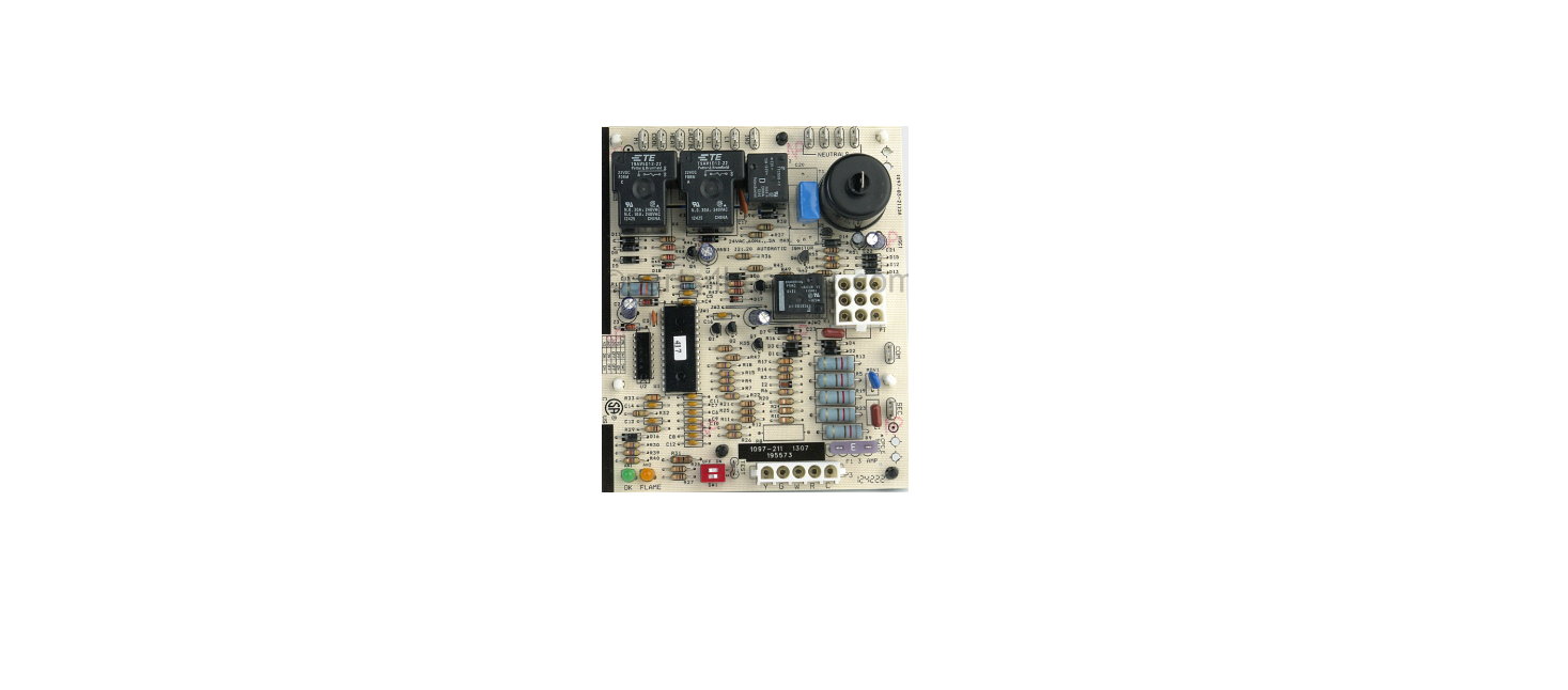

Renzor CAUA Ignition Controller Replacement Kit

Safety Instruction
To ensure safe and proper operation, read and follow these installation instructions. Failure to do so could result in property damage, personal injury, and/or death.
- These instructions are for replacing an obsolete ignition controller (RAM #3MC4-06, serial number code 76 or J/C #G822KCC-5401D, serial number code 77) with an ignition controller (see Figure 1) replacement kit (PN 258251).
- Refer to the installation manual provided with the heater for important safety information.
- Refer to the replacement parts manual at www.reznorhvac.com for serial number information.
- All serial number codes apply to original equipment only.
- Ensure that all components listed in Table 1 are available before beginning installation.


Installation
Install the ignition controller replacement kit as follows. Item numbers in parentheses refer to Table 1.
- Turn OFF the gas and electric power.
- Remove existing ignition controller: a. Open the control compartment and locate the ignition controller.
- Disconnect the wiring and the existing ignition cable from the controller.
- Remove four screws that secure the controller and remove the controller.
- Install replacement ignition controller: Position drill template (5), with painted side facing up, over mounting holes for ignition controller removed in step 2.
- Justify holes for the replacement controller toward the bottom of the panel.
- Mark and drill four 3/16-inch holes. Position the DSI control board (1) so that the spark transformer is located nearest to the spark electrode on the burner. Snap the control board into the holes.
- Install replacement ignition cable: Remove the existing Renzor CAUA Ignition Controller Replacement Kit ignition cable from the spark electrode on the burner.
- Connect one end of the replacement ignition cable (6) to the spark electrode on the burner and the other end to the spark transformer (see Figure 1) on the replacement DSI control board (1).

Connect Wiring
- Connect the P3 5-pin wire assembly (3) to the thermostat terminal strip as shown in Figure 1.
- Connect the P1 9-pin wire assembly (2) as shown in Figure 1.
- As necessary, shorten wires and install replacement terminals (8).
- Connect existing wires to the DSI control board (1) wire terminals.
- If the terminal on the line voltage wire is 3/16 inch, cut off the terminal, strip the wire, and install quick quick-connect terminal (7).
- Connect the line voltage wire to terminal L1. Connect one end of the 24-inch red wire assembly (4) to the rollout switch located on the burner box top.
- Connect the other end to the high limit switch wire lead using a wire nut (9).
- Install cable ties (10) as necessary for routing and excess wire length.
Adhere the wiring diagram label (12, see Figure 2) on the left panel inside the burner compartment.

Adhere the NOTICE label (11, see Figure 3) below the wiring diagram label installed in step 6.

Turn ON the electric power and gas, start up the heater, and check for proper operation.
Limited Warranty
Reznor LLC warrants to the original owner-user that this product will be free from defects in material and workmanship. This warranty is limited to twelve (12) months from the date of original installation, whether or not actual use begins on that date, or eighteen (18) months from the date of shipment, whichever occurs first.
Manufacturer Replacement Parts Limited Warranty
Reznor LLC warrants replacement parts for thirty (30) days after installation or thirteen (13) months from the date of shipment, whichever occurs first.
Customer Support
- Website: www.reznorhvac.com
- Ph: 800-695-1901