

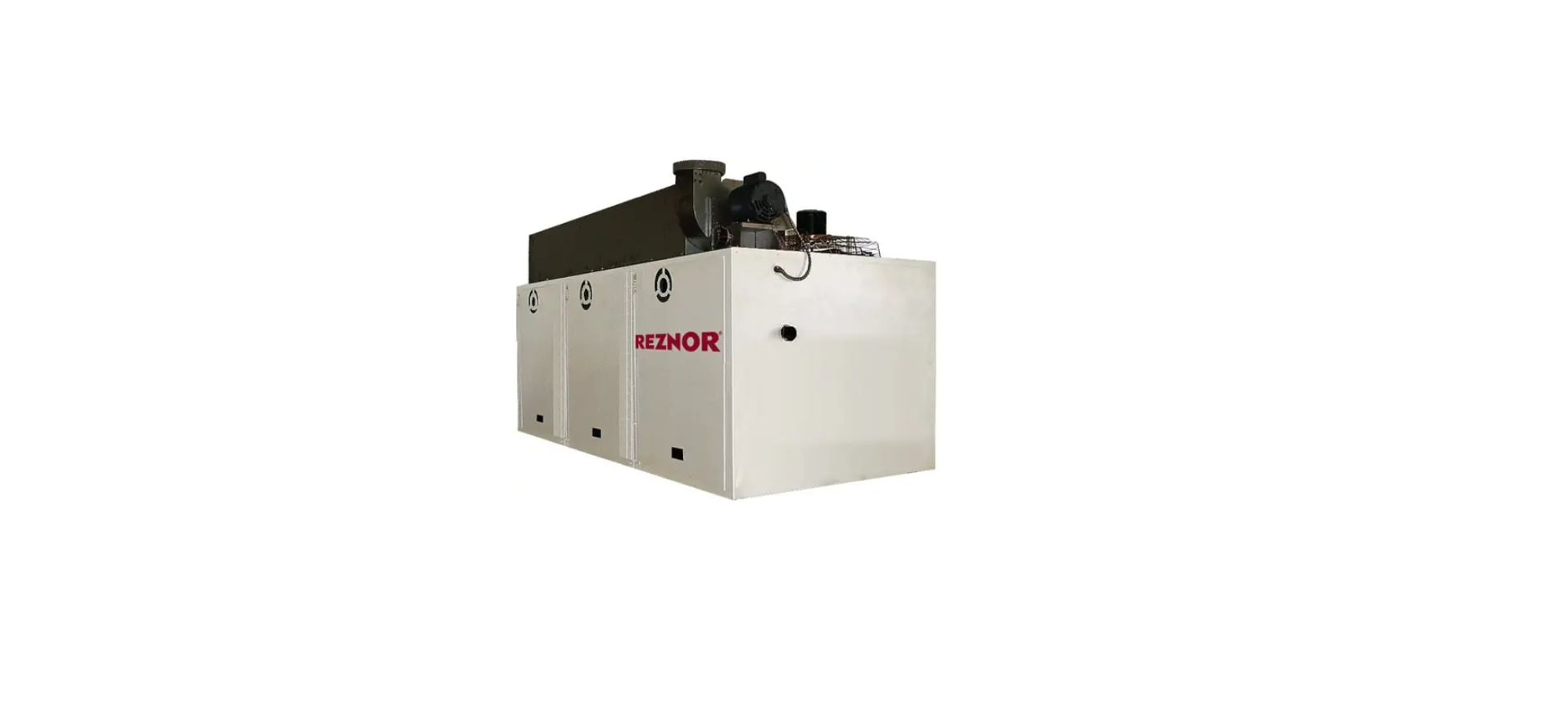

Renzor LDAP Downturn Nozzle Kit

General Information
- Downturn nozzles are designed to direct the discharge air in a more vertical flow.
- A discharge nozzle may be installed at each discharge air opening in any direction.
- Option CD57 provides 30-degree air deflection. Option CD58 provides 60-degree air deflection.
- Refer to the installation manual provided with the heater for important safety information.
- Ensure that all components listed in Table 1 are available before beginning installation.
Components
| Table 1. Nozzle Assembly Components | |||||||||||
| Component | Description | Unit Size | |||||||||
| 400 | 800 | 1200 | |||||||||
| Option | |||||||||||
| CD57 | CD58 | CD59 | CD57 | CD58 | CD59 | CD57 | CD58 | CD59 | |||
| Kit PN | |||||||||||
| 208094 | 208097 | 208100 | 208886 | 208888 | 208890 | 208887 | 208889 | 208891 | |||
| PN (Quantity)* | |||||||||||
| Nozzle section | Right side | 207932 | 207932
(2) |
207932 | 207932 | 207932
(4) |
207932 | 207932 | 207932
(6) |
207932 | |
| Left side | 207933 | 207933
(2) |
207933 | 207933 | 207933
(4) |
207933 | 207933 | 207933
(6) |
207933 | ||
| Top | 207934 | 207934
(2) |
207934 | 207934 | 207934
(4) |
207934 | 207934 | 207934
(6) |
207934 | ||
| Bottom | 207935 | 207935
(2) |
207935 | 207935 | 207935
(4) |
207935 | 207935 | 207935
(6) |
207935 | ||
| Filler | Nozzle side | 208747
(2) |
208747
(4) |
208747
(2) |
208747
(4) |
208747
(8) |
208747
(4) |
208747
(6) |
208747
(12) |
208747
(6) |
|
| Bag | Hardware | 208356 | 208357 | 208358 | 208356 | 208357 | 208358 | 208356 | 208357 | 208358 | |
| Screw** | Hex washer head, #8-18 × 3/8, AB point, slotted indented serrated | 195638
(20) |
195638
(46) |
195638
(38) |
195638
(20) |
195638
(46) |
195638
(38) |
195638
(20) |
195638
(46) |
195638
(38) |
|
| Spring** | Compression | — | 195046
(7) |
— | 195046
(7) |
— | 195046
(7) |
||||
| Louver | — | 195578
(7) |
— | 195578
(14) |
— | 195578
(21) |
|||||
| Support | Louver frame | — | 207937
(2) |
— | 207937
(4) |
— | 207937
(6) |
||||
Installation
Before installing a downturn nozzle, ensure that the installation location provides sufficient clearance—in accordance with the installation/operation/maintenance manual provided with the unit—for the nozzle option being installed. Install the downturn nozzle kit as follows:
- Assemble the downturn nozzle assembly (see Figure 1, DETAIL A)
- Secure both side sections to the top section using 3/8-inch screws.
- Secure both side sections to the bottom section using 3/8-inch screws.

- Install side fillers
- For options CD57 and CD58, secure side fillers to both side sections using 3/8-inch screws.
- For options CD58 and CD59, assemble the second nozzle without side fillers and connect both assembled nozzles using 3/8-inch screws (see Figure 1, DETAIL B).

- For option CD58, to install side fillers for the second nozzle, position each side filler over the seam between both bottom nozzle sections, remove screws that align with holes in each side filler, and reinstall screws to secure each side filler over the seam.
Option CD59
- Do not attach side fillers for the second nozzle—these will be installed in step 6b(3).
- If the heater is already installed, turn OFF the gas and electric power.
- Allow time for louvers to cool before proceeding.
- If horizontal louvers are already installed, remove each louver by pushing the louver toward the spring to release the louver. These will be reinstalled in step 5.
- Install the assembled nozzle in the heater outlet (see Figure 2)

The discharge opening is square, so the nozzle can be installed in any direction
- Determine the desired nozzle direction and position the assembled nozzle in the heater outlet so that the holes on each side align with the holes in the heater.
- Secure the nozzle sides to the heater using 3/8-inch screws, ensuring that the screw ends are inside the nozzle.
- Install 1/2-inch self-drilling screws inside the nozzle to secure the nozzle top and bottom, using the existing holes in the nozzle top and bottom to position the screws.
Before installing the louvers, note the louver curve and determine how the louvers should be positioned to provide the optimal throw pattern. Depending on where the heater is installed and on the desired airflow direction, the louvers may be installed with their curves all in the same direction (either way) or the right half one way, and the left the other. Reinstall the horizontal louvers removed in step 3 in the nozzle outlet.
- With a wider louver blade facing in toward the heat exchanger, push the tab with the compression spring into the hole in the top or bottom louver frame (Figure 3)—the spring compresses.
- Insert the tab on the other end of the louver into the opposite louver frame.
- For left airflow, compress the spring into the top Renzor LDAP Downturn Nozzle Kit louver frame.
- For the right airflow, compress the spring into the bottom louver frame.

Install all remaining louvers by steps 5a and 5b.
- For option CD59, install vertical louvers as follows
- Assemble louver frame (see Figure 4). Secure both sides to both supports using 3/8-inch screws.
- Install assembled louver frame:

Limited Warranty
Reznor LLC warrants to the original owner-user that this product will be free from defects in material and workmanship. This warranty is limited to twelve (12) months from the date of original installation, whether or not actual use begins on that date, or eighteen (18) months from the date of shipment, whichever occurs first.
Manufacturer Replacement Parts Limited Warranty
Reznor LLC warrants replacement parts for thirty (30) days after installation or thirteen (13) months from the date of shipment, whichever occurs first.
Customer Support
- Website: www.reznorhvac.com
- Ph: 800-695-1901